ELEXOL Espa 4.4.3 User manual
Manual for the Espa 443 to 444 converter page 1 Date: 23 Februari 2014
Manual of the
Espa 4.4.3
to
Espa 4.4.4.
converter
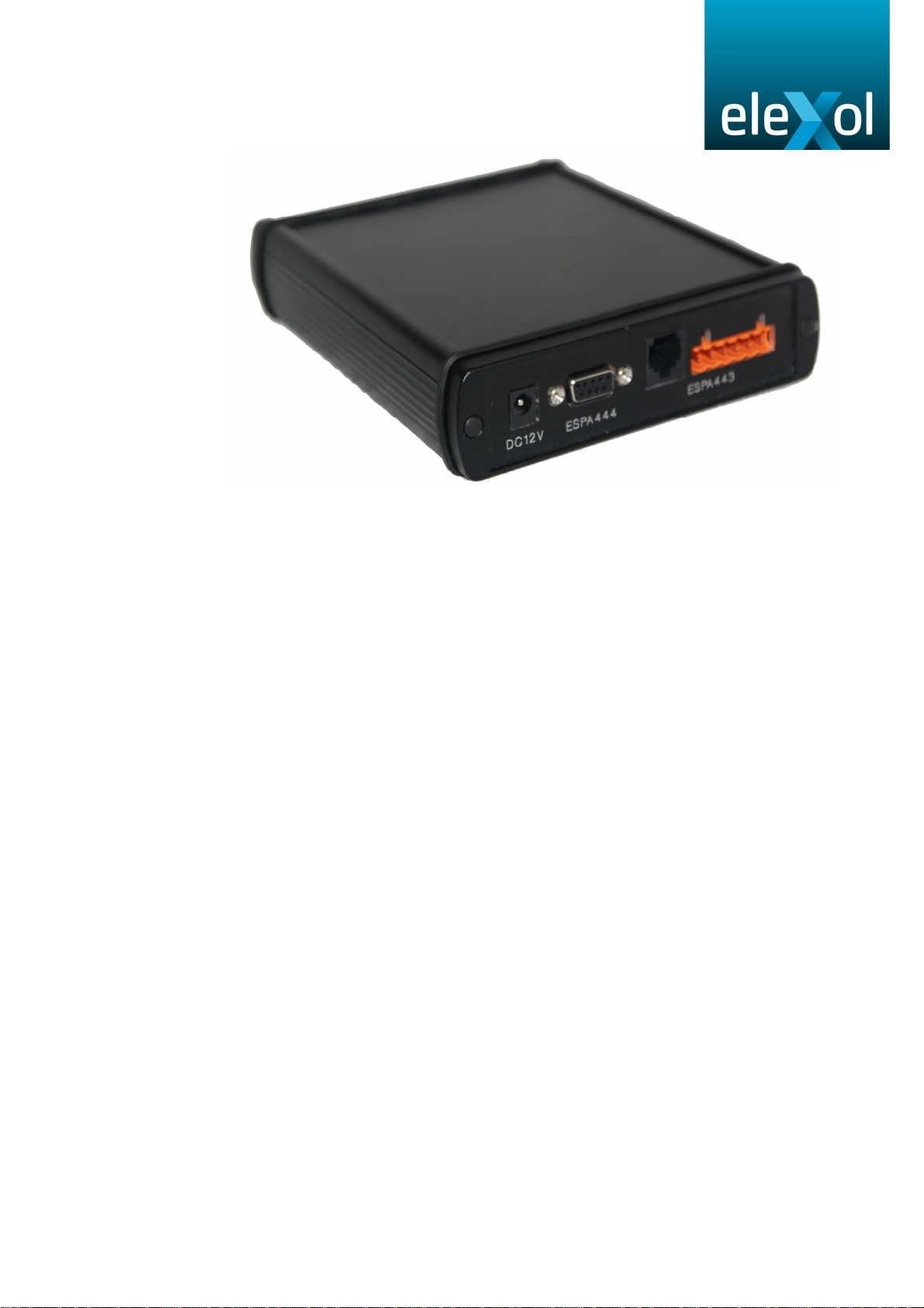
Espa 443 Converter
www.elexol.nl

Manual for the Espa 443 to 444 converter page 2 Date: 23 Februari 2014
Function of the converter 3
Connecting to an existing Espa 4.4.3. installation. 5
Connecting the power 8
Connecting the Espa 4.4.4. output. 9
How-to open the cover 11
Diagnose leds 12
Using the configuration port 13
Brief explanation about Espa 4.4.3. 14
Index

Manual for the Espa 443 to 444 converter page 3 Date: 23 Februari 2014
Function of the converter:
The Espa 4.4.3 to Espa 4.4.4. converter acts as a gateway between older Espa
4.4.3. systems and newer Espa 4.4.4. systems, creating the possibility to read Espa
4.4.3 messages from an older system and sent them to a Espa 4.4.4. installation.
The converter is connected to the PABX with:
M and M’ (Mouth contact)
E and E’ (Ear-contact),
A and B (600 ohm line)
When connecting the PABX to the converter make sure that the M and the E
contact are crossed. The Mouth contact for the PABX is like the Ear contact of the
converter.
PABX Converter
M+
M-
A
B
E+
E-
M+ (5)
M- (6)
A (3)
B (4)
E+ (1)
E- (2)
If a call is received via Espa 4.4.3. it will be translated to an Espa 4.4.4 call and
sent. The status that is received via Espa 4.4.4. will be forwarded to the Espa 4.4.3.
side, generating a ‘paged‘ or ‘absent‘ call on the Espa 4.4.3. side.
If the forward of the status is not needed (or the ESPA 4.4.4. system does not
generate a ‘paged‘ or ‘absent‘ status, the status generated on the ESPA 4.4.3. side
can be fixed to ‘paged’ .

Manual for the Espa 443 to 444 converter page 4 Date: 23 Februari 2014
Connecting to an existing Espa 4.4.3. installation:
The converter uses PhotoMos technology for the M contact. This contact is used in
Espa 4.4.3 to indicate to the PABX that all digits are received, and also to indicate
the Absent/Paged status.
The converter also has a build in supply to power the E contact. The supply is
limited to 12V 8mA. So if the PABX also supplies the E contact that should not
cause any problem. The current will be limited automatically. Please check the
polarity (+ and -) of the E contact before connecting the converter. A faulty polarity
will not harm the converter, but if the converter sends + 12V and the PABX sends –
12V, both signals end up as 0V, and are not detected by the converter.
The AB line are the lines over which the actual DTMF digits are sent from the PABX
to the converter.
If the total amount of digits is received by the converter, it will generate a ‘all digits
received’ puls on its M contact, indicating to the PABX that the digits are received. If
the amount of DTMF digits is insufficient, a time-out status will occur,
Manual for the Espa 443 to 444 converter page 5 Date: 23 Februari 2014
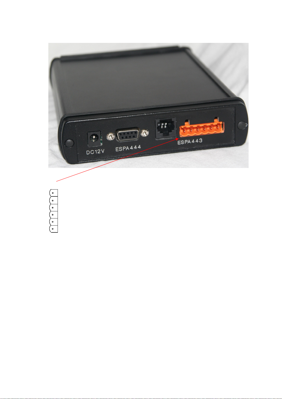
Connecting to an existing Espa 4.4.3. installation:
ESPA 4.4.3 IN 6pole screw-terminal
1: E+
2: E-
3: A
4: B
5: M (+)
6: M’ (-)
The E+ and E– inputs are connected to the M+ and M–
output contacts of the PABX. When the PABX wants to send
a message it will start by raising the M contact, connecting
M+ and M-. If the M+ and M– outputs of the PABX are not
isolated, or send power over the M+ and M- contacts, then
please note the polarity of that power. Please note that If the
PABX sends +10V to +16V over the M contact, the polarity is
important, because the converter uses its own power
generator of 12V to read the status of the M contact. If both
are 12V and the polarity is wrong, no M contact is detected.
Then switch the M+ and M– contact and it should be ok.
Internally the detector runs from 10V to 48V DC.
The polarity of the M+ and the M– contact is not important.
The contacts are used by the converter to indicate a status
present/paged/absent to the PABX on its M+ and M–
terminals.
The A and B terminals are used to send DTMF data to the
converter. If the PABX occupies the converter, the converter
can be programmed to generate a dailtone. Or a busy tone in
case the pager is absent.

Manual for the Espa 443 to 444 converter page 6 Date: 23 Februari 2014
Connecting to an existing Espa 4.4.3. installation:
ESPA 4.4.3 IN 8 pole RJ45 connector
Connector as shown:
1: E+
2: E-
4: A
5: B
7: M (+)
8: M’ (-)
1 2 3 4 5 5 6 8
Manual for the Espa 443 to 444 converter page 7 Date: 23 Februari 2014
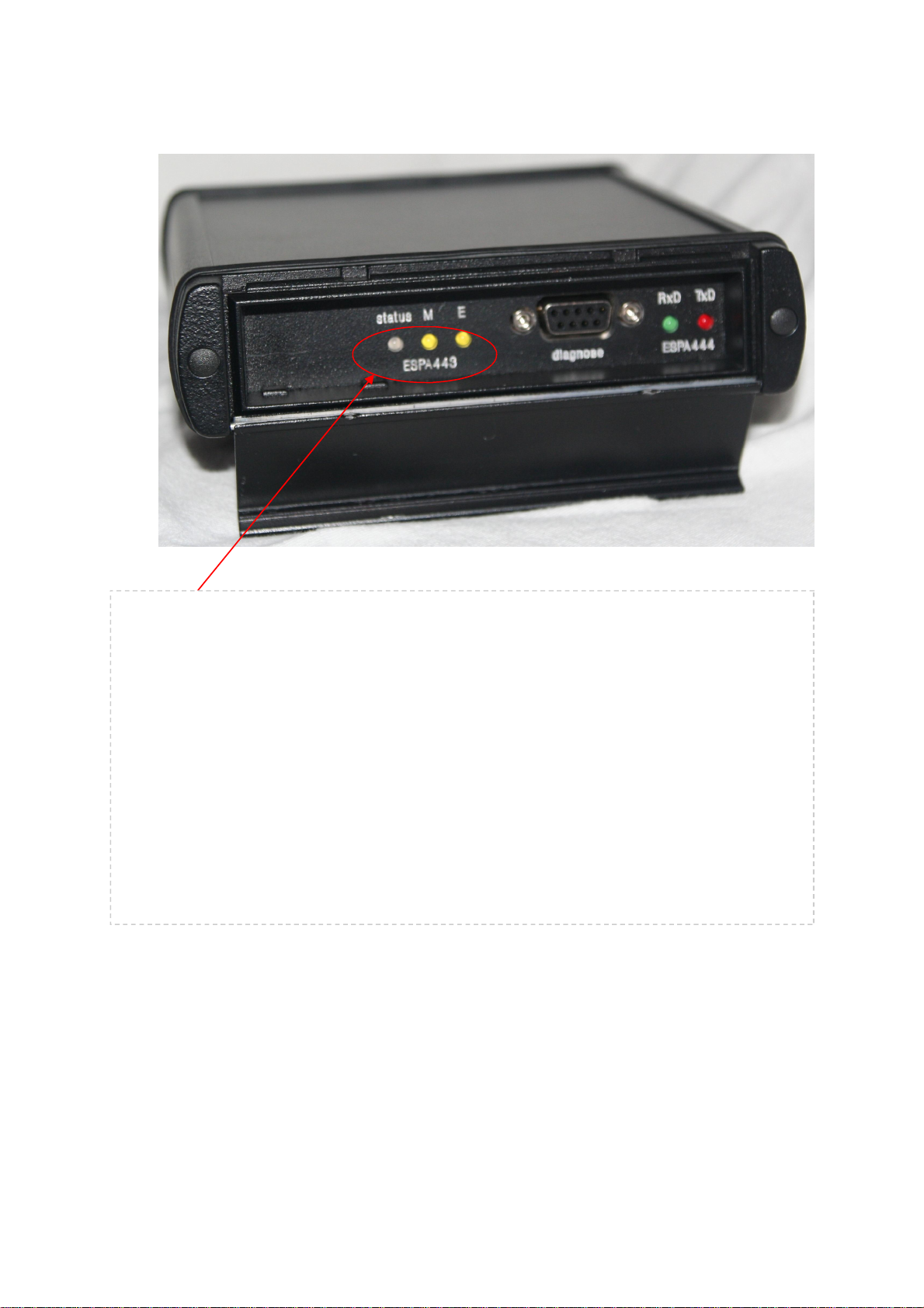
LED indicators for ESPA 4.4.3:
Status: Short green flash every second:
The converter is in idle state, no errors detected on ESPA 4.4.3 or
ESPA 4.4.4. side. No calls present in buffer.
Long green flash every second:
The converter is in idle state, no errors detected on ESPA 4.4.3. or
ESPA 4.4.4. side. But there are calls to be transferred in the buffer.
Short red flash every second:
An error is detected.
Long red flash every second:
An error has occurred, and the error is remaining.
Short orange flash:
DTMF data is received.
MThis LED indicates that the converter has activated the M contact .
EThis LED indicates that the E input of the converter is activated by the PABX..

Manual for the Espa 443 to 444 converter page 8 Date: 23 Februari 2014
Connecting the power:
The power supply of the converter is 12V DC.
Please us the supplied power supply.

Manual for the Espa 443 to 444 converter page 9 Date: 23 Februari 2014
Connecting the Espa 4.4.4. output:
The converter uses a standard 9 pole SUBD connector with RS232 to
communicate with its peripheral (PC or other system).
The pin-layout is::
Pin 2: TxD
Pin 3: RxD
Pin 5: GND
Pin 7: CTS
Pin 8: RTS
The pin 7 and pin 8 are used for hardware handshake. With a software tool
you can select if the hardware handshake is used or not.
We strongly advise to use the locking screws to connect the plug to the
converter.
Manual for the Espa 443 to 444 converter page 10 Date: 23 Februari 2014
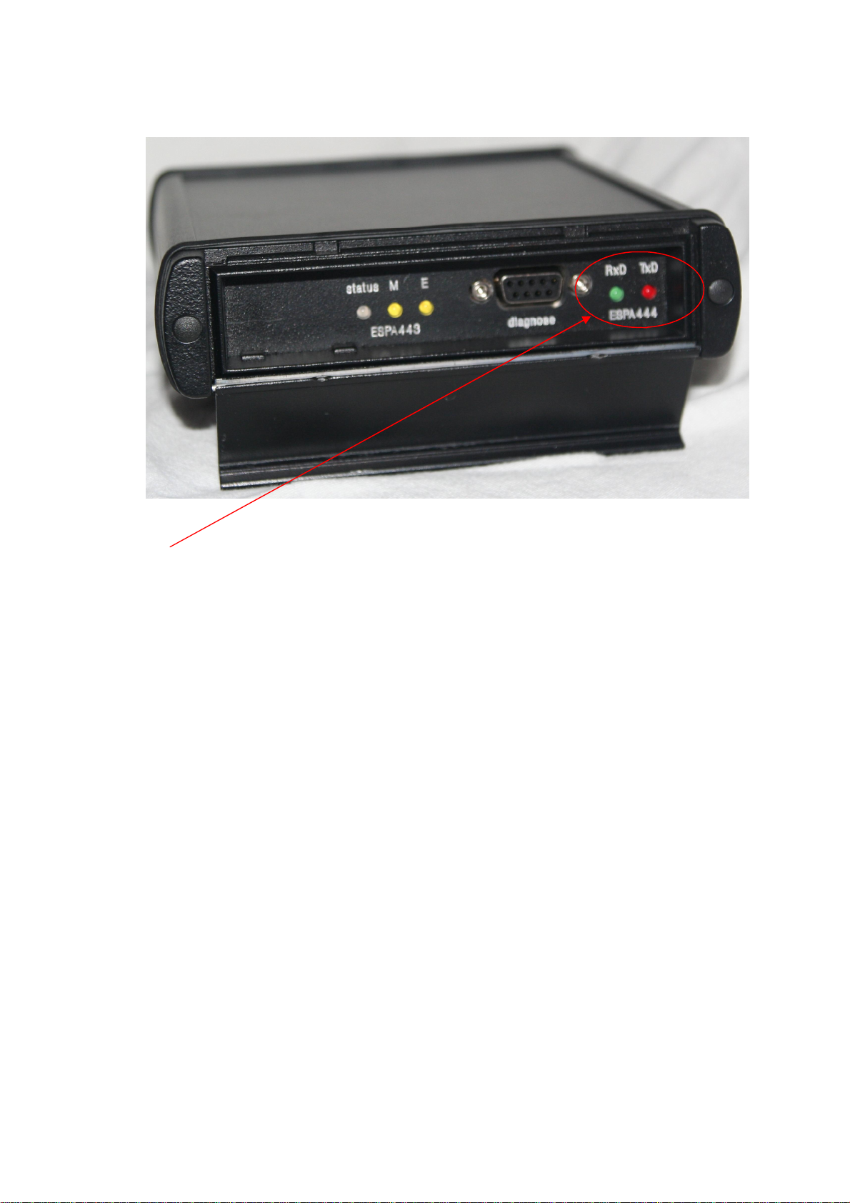
Connecting the Espa 4.4.4. output:
The TxD and RxD leds indicate the communication on the RS232 serial lines
to the ESPA 4.4.4. device. If data is sent, the red led lights up shortly, if data is
received the green led lights up shortly.
Manual for the Espa 443 to 444 converter page 11 Date: 23 Februari 2014
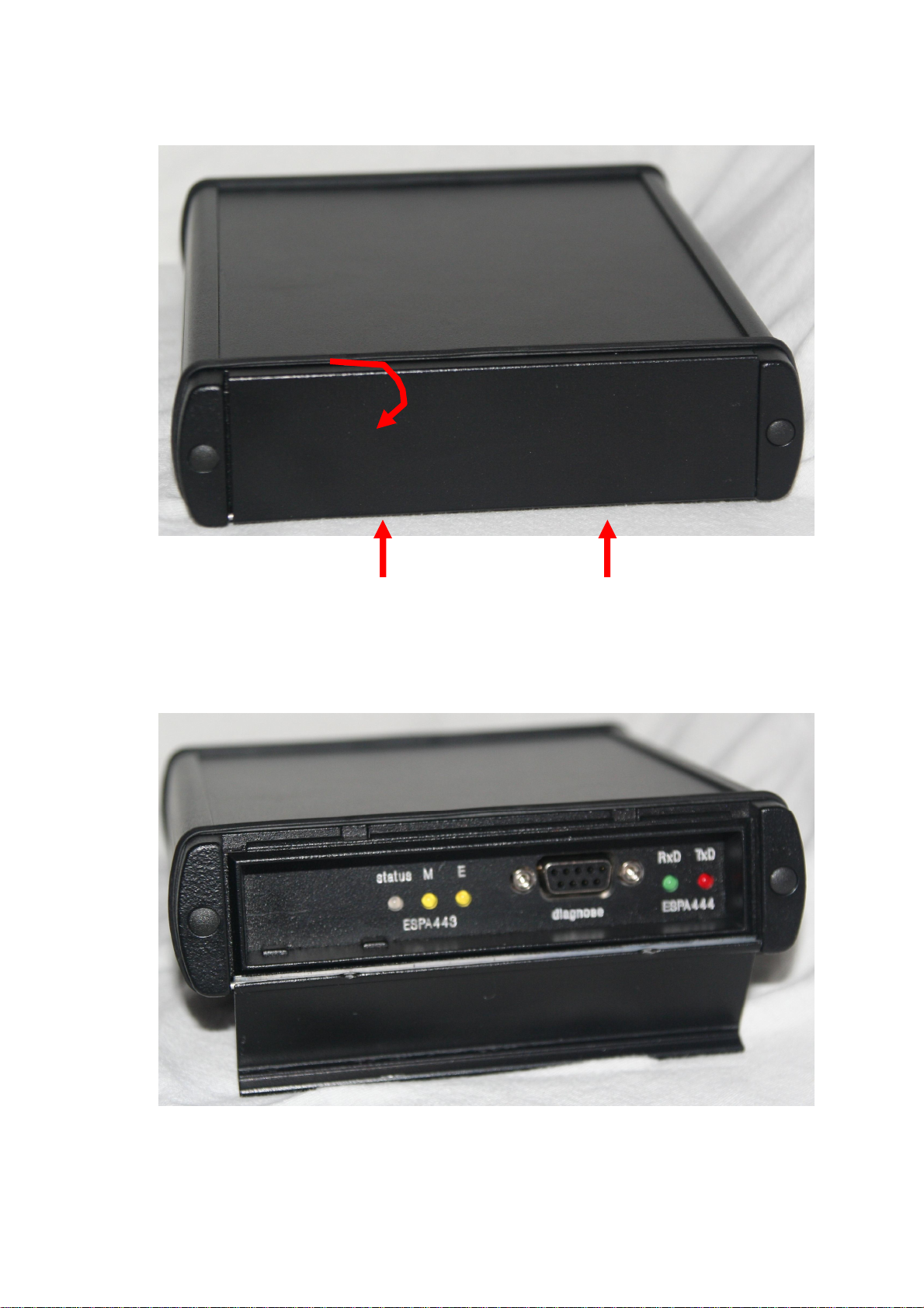
Howto open the cover:
To open the cover push it into the upper direction, then opening it by the use
of a screwdriver into one of the two small holes on the top side of the cover.

Manual for the Espa 443 to 444 converter page 12 Date: 23 Februari 2014
Diagnose leds:
Status: Short green flash every second:
The converter is in idle state, no errors detected on ESPA 4.4.3 or
ESPA 4.4.4. side. No calls present in buffer.
Long green flash every second:
The converter is in idle state, no errors detected on ESPA 4.4.3. or
ESPA 4.4.4. side. But there are calls to be transferred in the buffer.
Short red flash every second:
An error is detected.
Long red flash every second:
An error has occurred, and the error is remaining.
Short orange flash:
DTMF data is received.
MThis LED indicates that the converter has activated the M contact .
EThis LED indicates that the E input of the converter is activated by the PABX..
RxD This LED indicates data being received by the converter from the connected system.
TxD This LED indicates data being sent by the converter to the connected system.

Manual for the Espa 443 to 444 converter page 13 Date: 23 Februari 2014
Using the configuration port:
If needed, the converter can be setup with a ‘ConfigTool’.
This is a program running under Windows XP, Vista, 7 and 8 using the serial port of a computer of a
laptop.
It can be used to program settings into the converter, reading current settings out of the converter
and to read serial diagnose information
All settings that can be programmed via the ConfigTool software are documented in the ConfigTool
documentation.

Manual for the Espa 443 to 444 converter page 14 Date: 23 Februari 2014
Brief explanation about Espa 4.4.3:
Espa 4.4.3 is used to interface between a PABX and a paging system based on
transmitting DTMF digits. These digits may be: ‘0’ till ‘9’, ‘*’, ‘#’, ‘A’, ‘B’, ‘C’ and ‘D’.
Whereas the digits 0 to 9 are mostly used.
In an idle situation the converter has its M contact activated (closed) indicating to
the PABX that the converter is present and ready to accept new calls.
A call is initiated by the PABX by activating the M contact on the PABX. This is
detected on the E input on the converter side. The converter will send a dial-tone (if
needed) to the PABX. The PABX might react on this dailtone, but it should not be a
blocking issue.
The PABX will sent the call by sending DTMF digits over the AB terminals.
If all digits are received, the converter will indicate to the PABX that ‘all digits are
received’ by interrupting its M contact for a short period (50 milliseconds). The
PABX will detect this on its E input.
The converter will then send the call via ESPA 4.4.4. to the other system, and wait
for the status of the call. This will be absent or paged.
Once the status is known to the converter, it will sent the status via the M contact of
the converter to the E input of the PABX indicating absent or paged.
When the PABX has received the status, it will stop the transfer by bringing its M
output to the idle state.
Then the next message can be sent.
Please note:
The number of DTMF digits that can be sent is not specified in the protocol. The
converter can handle this in 2 ways:
A. Setup the number of digits to be received (for example 10 digits)
B. The number of digits is variable, but all calls will be ended with a #.
Once all the digits are transmitted, there are different possibilities about how this
ESPA 4.4.3. string of data is build up:
A. How many digits are for the address of the pager
B. Where is the digit indicating the bleepcode of the pager
C. Is there any information that should be sent to the display of the pager?
All these settings can be done with the ConfigTool. First the converter will receive all
the digits and then convert them (if needed) to match the arguments needed on the
ESPA 4.4.4. side. It is also possible to sent calls when only the pagernumber is
received. All other information will then be added by the converter.
This manual suits for next models
1
Table of contents
Other ELEXOL Media Converter manuals

Popular Media Converter manuals by other brands


H&B
H&B TX-100 Installation and instruction manual

Bolin Technology
Bolin Technology D Series user manual

IFM Electronic
IFM Electronic Efector 400 RN30 Series Device manual

GRASS VALLEY
GRASS VALLEY KUDOSPRO ULC2000 user manual

Linear Technology
Linear Technology DC1523A Demo Manual

Lika
Lika ROTAPULS I28 Series quick start guide

Weidmuller
Weidmuller IE-MC-VL Series Hardware installation guide

Optical Systems Design
Optical Systems Design OSD2139 Series Operator's manual

Tema Telecomunicazioni
Tema Telecomunicazioni AD615/S product manual

KTI Networks
KTI Networks KGC-352 Series installation guide

Gira
Gira 0588 Series operating instructions

Lika
Lika SFA-5000-FD user guide