ELFBULB ELF52V-200-10K-WM User manual

=
Easy for installation and maintenance with software BMS monitoring
Support high current charging/discharging
Support RS485,RS232 and CAN communications
Intelligent BMS can be compatible with most of the inverter brands in
the market
ELF52V-200-10K-WM

BMS communication protocol is compatible with the following brands of inverters
ITEM SPECIFICATIONS
Model
Nominal Voltage
Capacity
Energy
Equalizad Charge Voltage
Float Charge Votage
Max.Continuous Charging Current
Max.continuous Discharge Current
Max C Rating
Parallel
Communication interface
Battery Cells
Design Life
Cycle Life
Certification
Operating Temperature
Storage
Protection
Net Weight(KGS)
Dimension
Warranty 10 years or 3500 cycles whichever comes first
Brand
GOODWE
PYLON
VICTRON
GROEATT
lUXPOWEP
V1800F
SUNSUYNK
SOFAR
Protocol
CAN
CAN
CAN
CAN
CAN
CAN
CAN
CAN
Baud Rate
500K
500K
500K
500K
500K
500K
9600
500K
Brand
SOROTEC
MEGAREVO
VOLTRONIC POWER
SRNE
DEYE
SMA
SOLIS
Protocol
CAN
CAN
RS485
RS485
CAN
RS485
RS485
Baud Rate
500K
500K
9600
9600
500K
9600
9600
Wall-Mounted
51.2V
200Ah
10.24KWh
58.4V
54.4V
200A
200A
1C
Parallel Connection up to 15 packs with full communications
RS485/RS232/CAN
Lithium Iron Phosphate(LifePO4)
10+ Years
Above 6000 cycles @80%DOD,+/-3500 cycles@100%DOD
CE,UN38.3,MSDS
Charging:0 to +50℃,Discharging:-10 to +50℃
-10 to +55℃
Electronic Circuit Breaker,BMS Voltage Protection,Current Limiting
88KGS
590*375*245
EBW-05-10
1
Wall-Mounted Lithium battery User Manual
5.12KWh/10.24KWh wall-mounted energy storage battery
Thank you for using this product, ELFBULB is committed to providing high-quality, most
cost-effective energy products to users all over the world

EBW-05-10
https://www.elfbulbpower.com
2
Important Safety Instructions, Precautions
Please keep this manual for future reference
This manual contains all safety, installation and operation instructions for EBW-05-10
wall-mounted energy storage.
Please read all instructions and precautions in the manual carefully before installation
and use. The company does not undertake the violation of general safety operation
requirements or safety standards in the design, production and use of equipment
any responsibility.
There is an unsafe voltage inside the energy storage battery. To avoid personal
injury, users should not disassemble it by themselves. For maintenance, please contact
professional maintenance personnel.
Precautions
●During the installation process, it is strictly forbidden to operate with power on, and
connect the wires correctly during installation, and do not connect them inreverse.
●Please ensure that the parameters between related devices are compatible and
matched.
●Please ensure that the installation environment of the equipment is wellventilated.
●When the equipment is running, do not block the vents or heat dissipation system
to prevent fire caused by high temperature.
●Do not place the device in an environment of flammable, explosive gas or smoke, or
high-salt spray environment, nor perform any operations in this environment.
●The load strength of the mounting surface should be greater than the load caused
by the weight of the product.
●Please be properly grounded before use to ensure your safety.
●The annual temperature of the installation area should be between 0°C and 50°C.
●The relative humidity of the air should be less than 85%
https://www.elfbulbpower.com
EBW-05-10
3
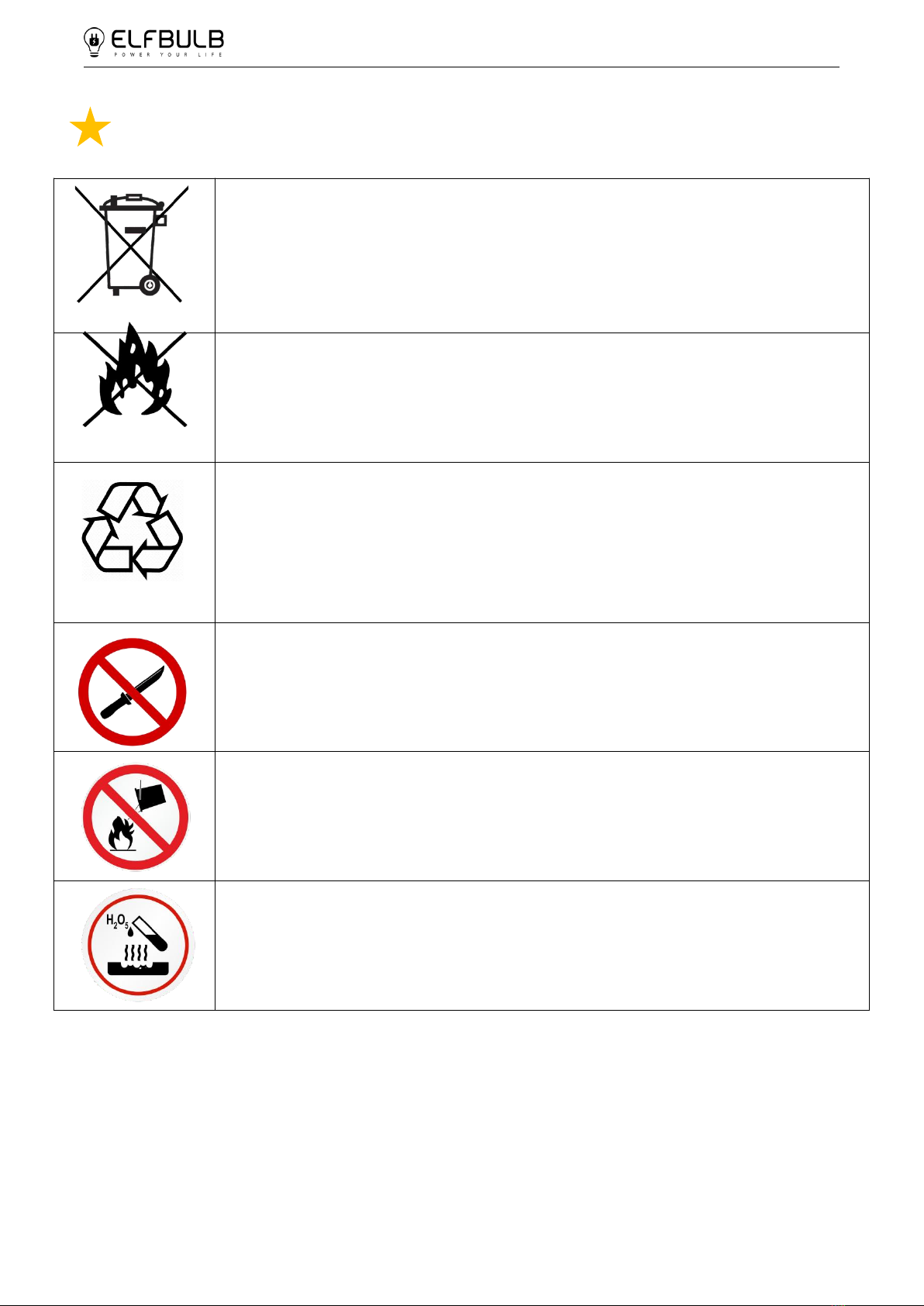
Warning
The scrapped battery cannot be put into the garbage can and must be
professionally recycled.
Do not place near open flame
After the battery life is terminated, the battery can continue to be used
after it recycled by the professional recycling organization and do not
discard it at will.
Do not cut or spear with sharp objects
Do not extinguish with water in case of fire
Do not use in corrosive environment

https://www.elfbulbpower.com
EBW-05-10
4
Contents
1. Basic Information.......................................................................................5
1.1 Product overview and features.......................................................................................................5
1.2 Basic parameters..................................................................................................................................6
1.3 Product function introduction........................................................................................................7
1.4 Dimensions ...........................................................................................................................................9
2. Installation Instructions...........................................................................10
2.1 Installation preparation.................................................................................................................10
2.2 Engineering coordination..............................................................................................................10
2.3 Equipment installation....................................................................................................................11
2.4 Parallel connection...........................................................................................................................12
2.5 Introduction........................................................................................................................................13
2.6 Electrical interface check................................................................................................................14
2.7 Electrical installation........................................................................................................................14
2.8 Use, maintenance and troubleshooting...................................................................................15
3. Operating mode.......................................................................................16
3.1 Charging voltage protection and charging current protection.........................................16
3.2 Discharge voltage protection and discharge current protection......................................17
3.3 Ambient temperature alarm protection....................................................................................19
3.4 Other Protection................................................................................................................................19
3.5 Key description and buzzer action description.......................................................................20
3.6 Working status of the indicator light.........................................................................................21
4. Communication Description...................................................................23
4.1 RS232.....................................................................................................................................................23
4.2 CAN........................................................................................................................................................23
4.3 RS485.....................................................................................................................................................23
4.4 DIP switch setting..............................................................................................................................23
4.5 Communication interface definition as shown below..........................................................26
4.6 Electrical interface definition.........................................................................................................27
4.7 Compatible to brand inverter.......................................................................................................29
5. Storage and use environment requirements........................................30
6. Attachment table......................................................................................30

https://www.elfbulbpower.com
EBW-05-10
5
1. Basic information
1.1 Product overview and features
Our products have been strictly tested and inspected before leaving the factory. If
you find any abnormalities in the equipment, please contact the provider.
EBW-05-10 wall-mounted energy storage battery is a device used to store energy in
a photovoltaic solar system.
Product features: This product is composed of high-quality lithium iron phosphate
aluminum shell cells, high-efficiency BMS, and anti-static metal shell. The square
aluminum shell cell has high stability and fast heat dissipation. The BMS effectively
manages overcharge and over discharge, short circuit, and over temperature. The
thickened metal shell has better protection performance.
Features of the system: EBW-05 can provide 100A continuous discharge and 100A
charging capacity (recommended charging below 100A); EBW-10 can provide 200A
continuous discharge and 200A charging capacity (recommended 100A) .It supports
6000 cycles of 80% DOD. A larger capacity battery pack can be formed by parallel
connection to meet the long-term power supply needs of users. The closed line design
is adopted to effectively prevent dust and mosquitoes from blocking the interface and
increase the safety of use.

https://www.elfbulbpower.com
EBW-05-10
6
1.2 Basic parameters
EBW-05: 51.2V100Ah EBW-10: 51.2V200Ah
ITEM
SPECIFICATIONS
Model
Nominal Voltage
51.2V
Capacity
100Ah
Energy Power
5.12Kwh
Equalized Charge Voltage
58.4V
Float Charge Voltage
44.8V
Max.Continuous Charging Current
100A(Recommended 50A )
Max.Continuous Discharging Current
100A
Max C Rating
1C
Model
Nominal Voltage
51.2V
Capacity
200Ah
Energy Power
10.24Kwh
Equalized Charge Voltage
58.4V
Float Charge Voltage
44.8V
Max.Continuous Charging Current
200A(Recommended 100A )
Max.Continuous Discharging Current
200A
Max C Rating
1C
ELF52V-100-5.12K-WM
ELF52V-200-10K-WM

https://www.elfbulbpower.com
EBW-05-10
7
1.3 Product function introduction
Function table
NO
Name
Function
1
Handle
For moving
2
Display screen
Show battery status
3
Button
Battery Settings, battery status checking
4
Indicator light
Battery status indicator
5
Self-locking switch
ON / OFF

https://www.elfbulbpower.com
EBW-05-10
8
6
Bracket
Support or fix the battery
7
Cable hole
Make the positive .negative wire and
communication cable pass through
8
Cover plate
Keep out dust and safety protection
9
Foothold
Prevent the battery from directly touching the
ground and damaging the surface
10
Negative terminal
Connect the negative wire
11
RS485-B
RS485-B Communication
12
RS485-A
RS485-A Communication
13
Positive terminal
Connect the positive wire
14
RS232
RS232 Communication
15
CAN
CAN Communication
16
RS485
RS485 Communication
17
Dry contact
/
18
ADS
Battery parallel Communication settings
19
Breakers
Leakage short circuit protection
20
Heat sink hole
Heat dissipation and dust isolation

https://www.elfbulbpower.com
EBW-05-10
9
1.4 Dimensions
.
EBW-05
EBW-10

EBW-05-10
https://www.elfbulbpower.com
10
2. Installation instructions
2.1 Installation preparation
1. Safety Requirements: This system should only be installed by personnel who
have received training in power systems and have sufficient knowledge of power
systems. During installation, the safety regulations described below and local safety
regulations should always be followed.
2. Make sure that all devices are powered off before operating, and use devices or
accessories that match the battery parameters.
3. The wiring of power distribution cables should be reasonable and haveprotective
measures to avoid contact with these cables when operating power equipment.
4. Wear appropriate protective measures, such as: goggles, gloves, installation
clothing, etc.
5. Need to prepare installation tools:
Drill
Hammer
Wrench
Screw
Wire strippers
Insulating tape
Electric pencil
Multi meter
Pliers
Measuring
ruler
2.2 Engineering coordination
Attention should be paid to the following items before construction.
Power line specification:The power line specification shall meet the requirements of
maximum discharge current for each product.
Mounting space and bearing capacity: Make sure that the batteries has enough room
to install, and that the batteries rack and bracket have enough load capacity.
Make sure the power line and ground wire are reasonable. Not easy to short-circuit
water and corrosion
EBW-05-10
https://www.elfbulbpower.com
11
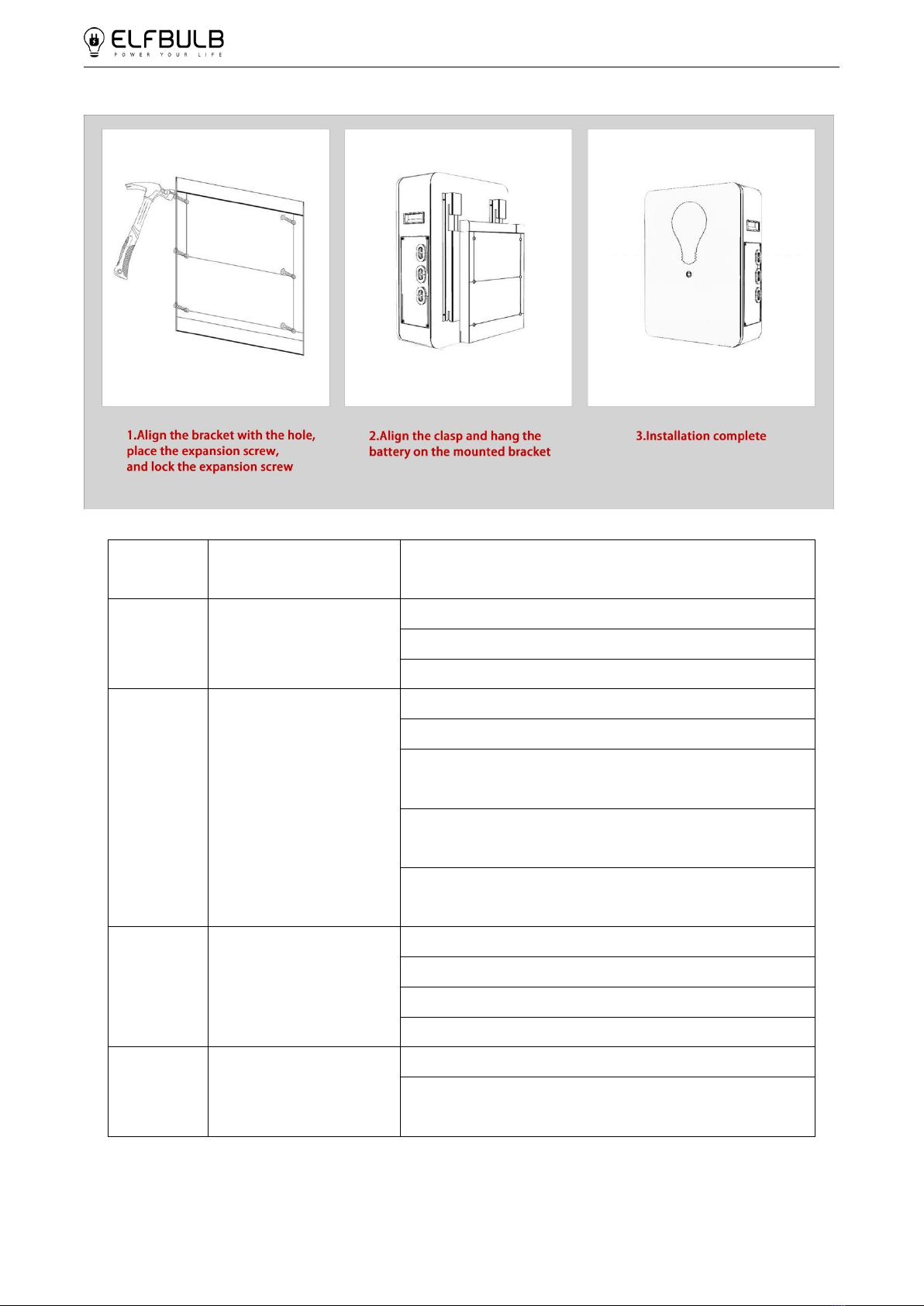
2.3 Equipment installation
Step1
Installation
preparation
Confirm that the ON/OFF switch is off on the
front panel of EBW-05-10
Step2
Mechanical
Installation
1.Cabinet placement position determination
2.Top cable harness pre-installed
3.Batteries module installation
Step3
Electrical
Installation
1. Batteries module parallel cable installation
2. Batteries module total positive cable
installation
3. Batteries module total negative cable
installation
4. Internal RS485 communication interface
connection
Step4
Batteries
System self-test
1. Press the ON/OFF switch to the "ON" state
2.BMS system power on activation
3. Check the system output voltage
4. Shut down the system
Step5
Connecting inverter
1.Connect total positive & total negative cable
2. Connect the external RS485
communication cable to the inverter

EBW-05-10
https://www.elfbulbpower.com
12
2.4 Parallel connection
EBW-05-10
https://www.elfbulbpower.com
13
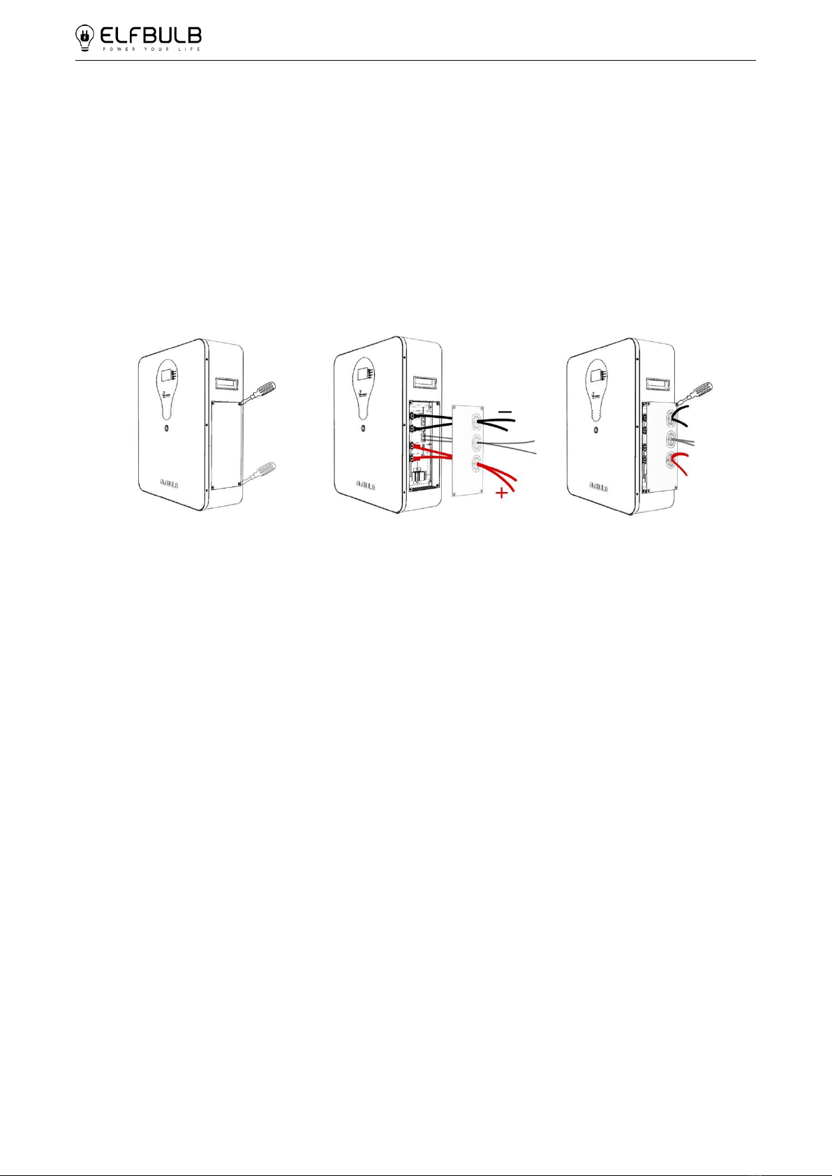
2.5 Introduction
1. Prepare the screwdriver, cable set, communication line
2. Remove the cover plate with a screwdriver, pass the positive pole, negative pole,
and communication wire through the cover plate and the coil respectively. After
debugging, lock the cover plate and press the switch before use. As shown in the
picture:

EBW-05-10
https://www.elfbulbpower.com
14
2.6 Electrical interface check
Devices that connected directly to the batteries can be user equipments, power
supplies,and other power supplies.
Please check if the user's PV power generation equipment, power supplier or other
power supply equipment has a DC output interface, and the voltage meet the
requirements of the inverter.
And check the maximum discharge current capability of the DC power interface of the
user's photovoltaic power generation equipment, power supply or other power
supply equipment should be greater than the maximum charging current of the
products.
2.7 Electrical installation
Before connecting the power cables, using multi meter to measure cable continuity,
short circuit, confirm positive and negative, and accurately mark the cable labels.
Measuring methods:
Cable availability: select the buzzer and use the probe to measure the ends of the
same color cable. If the buzzer calls, it means the cable is available.
Short circuit judgment: choose multi meter resistor file, probe the same end of
positive and negative pole, if the resistor shows infinity, means that the cable is
available.
After visual testing of power line is connected well, the positive and negative poles of
the batteries shall be connected respectively to the positive and negative poles of the
opposite terminal.
It is better to add a circuit breaker between the inverter and the batteries system. The
selection of the circuit breaker requires:
Voltage: U>60V
Current: | =Inverter Power
43V

EBW-05-10
https://www.elfbulbpower.com
15
2.8 Use, maintenance and troubleshooting
Batteries system usage and operation instructions
After completing the electrical installation, follow these steps to start the batteries
system
1.Refer to 1.3, Press the self-locking switch to ON position, The display screen and
indicator will light up
2.After the indicator self-test, the RUN indicator will light and the SOC indicator will
be on.
Note:
1. After pressing the power button, if the batteries status indicator on the front panel
continues to be red, please refer to the "3.5 Alarm description and processing ".If the
failure cannot be eliminated, please contact the dealer timely.
2. Use a voltmeter to measure whether the voltage of the circuit breaker batteries access
terminal is greater than 43V, and check whether the voltage polarity is consistent with the
inverter input polarity. If the circuit breaker batteries input terminal has a voltage output
and is greater than 43V, then the batteries has started normal work.
3.After confirming that the batteries output voltage and polarity are correct, turn on the
inverter, close the circuit breaker.
4 Check if the indicator of the inverter and batteries connection (communication
indicator and batteries access status indicator)is normal. if it is normal, successfully
complete the connection between the batteries and the inverter. If the indicator light is
abnormal, please refer to the inverter manual for the cause or contact the dealer.

EBW-05-10
https://www.elfbulbpower.com
16
3. Operating mode
3.1 Charging voltage protection and charging current protection
Overcharge protection
Overcharge warning voltage
56.8V
Overcharge protection voltage
57.6V
Overcharge protection delay
1.0S
Charging voltage protection
Charging current protection
Charging over current protection
Charging over current warning current
100A
Charging over current protection current
105A
Charge over current protection delay
1.0S
ELF52V-100-5.12K-WM

EBW-05-10
https://www.elfbulbpower.com
17
overcharge protection
Overcharge warning voltage
56.8V
Overcharge protection voltage
57.6V
Overcharge protection delay
1.0S
Charging voltage protection
Charging current protection
3.2 Discharge voltage protection and discharge current protection
over-discharge protection
Over-discharge warning voltage
44.8V
Over-discharge protection voltage
44V
Over-discharge protection delay
1.0S
Discharge voltage protection
Charging over current protection
Charging over current warning current
205A
Charging over current protection current
210A
Charge over current protection delay
1.0S
ELF52V-200-10K-WM
ELF52V-100-5.12K-WM

EBW-05-10
https://www.elfbulbpower.com
18
Discharge over
current 1 protection
Discharge over current 1 alarm current
100A
Discharge over current 1 protection current
105A
Discharge over current 1 protection delay
5.0S
Discharge over
current 2
Discharge over current 2 protection current
≥120A
Discharge over current 2 protection delay
1500mS
Discharge current protection
over-discharge protection
Over-discharge warning voltage
44.8V
Over-discharge protection voltage
44V
Over-discharge protection delay
1.0S
Discharge voltage protection
Discharge over
current 1 protection
Discharge over current 1 alarm current
205A
Discharge over current 1 protection current
210A
Discharge over current 1 protection delay
5.0S
Discharge over
current 2
Discharge over current 2 protection current
≥250A
Discharge over current 2 protection delay
1500mS
Discharge current protection
ELF52V-200-10K-WM
This manual suits for next models
1
Table of contents
Popular Batteries Pack manuals by other brands

Delta
Delta PB-S1000 user manual

Tripp Lite
Tripp Lite BP24V9T owner's manual

Tripp Lite
Tripp Lite BP240V5RT2U Specifications

MasterPower
MasterPower GreenE 3.68K Installation, operation & maintenance manual

Pro-Team
Pro-Team GoFree Flex Pro 107724 owner's manual

Tripp Lite
Tripp Lite BP192V18-4U Specification sheet


