Odyssey PC310 User manual

ENGINEERED WITH THIN PLATE PURE LEAD (TPPL) TECHNOLOGY
OWNERS MANUAL
EXTREME POWER
AND ENDURANCE
www.odysseybattery.com

INTRODUCTION
The ODYSSEY® battery ingeniously uses absorbed glass mat (AGM) technology to offer, in one box, the
characteristics of two separate batteries. It can deep cycle as well as provide enormous cranking power –
it is almost as if a champion long distance runner and a world class sprinter are one and the same person.
These batteries are capable of providing engine cranking pulses in excess of 2250A for 5 seconds as well as 400
charge/discharge cycles to 80% depth of discharge (DOD). A typical starting, lighting and ignition (SLI) battery can
do one or the other, but not both. It is either a sprinter or a long distance runner; ODYSSEY batteries will do both –
provide short duration high amperage pulse or low rate long duration drains.
In order to achieve the full design cycle life of ODYSSEY batteries in cyclic applications the charge current must be
a minimum of 40% of the battery’s 10-hour rating (column 8 of the chart on page 5). Thus the minimum charge
current for a PC925 battery in a cycling application is 10.8 amps (40% of 27Ah). Please refer to Figure 6 of the
ODYSSEY Technical Manual for a detailed discussion of the recommended charge profile for ODYSSEY batteries in
cycling applications. The manual may be downloaded from www.odysseybattery.com.
WHY USE ODYSSEY®BATTERIES?
GUARANTEED LONGER SERVICE LIFE
With an eight to twelve year design life (float) and a three to ten year service life, ODYSSEY batteries save you time
and money because you do not have to replace the battery as often. ODYSSEY batteries are warranted against
factory defects for two (2) years for powersports applications; three (3) years in automotive, marine, commercial and
industrial applications and; four (4) years in the case of the PC1220, 75-PC1230, 75/86-PC1230, PC1350, 25-PC1400,
35-PC1400, 34-PC1500, 34M-PC1500, 34R-PC1500, 34/78-PC1500, 78-PC1500, 65-PC1750, 31-PC2150 and
PC2250 batteries. Since actual warranty can vary with your geographical location, please check with your ODYSSEY
Extreme Series battery representative for the warranty specific to your application.
SUPERIOR CRANKING AND FAST CHARGE CAPABILITY
The 5 second cranking power of ODYSSEY batteries is double to triple that of equally sized conventional batteries,
even when the temperature is as low as -40°F (-40°C). Also, with simple constant voltage charging (alternator or
independent charger), there is no limitation on the inrush current, so the user is assured of fast charge recovery.
MOUNTING FLExIBILITY
The ODYSSEY battery may be installed in any orientation (except inverted) without sacrificing any performance
attributes. There is no fear of any acid spillage as ODYSSEY batteries recycle the internal gas during operation or
charging. The valve regulated design of the ODYSSEY battery eliminates the need for an acid vent tube; eliminating
the fear of acid burns or damage to expensive chrome or paint.
SUPERIOR VIBRATION RESISTANCE
ODYSSEY batteries have endured rigorous tests that demonstrate their overall ruggedness and exceptional tolerance
of mechanical abuse.
READY OUT OF THE BOx
ODYSSEY batteries are shipped fully charged. If the ODYSSEY battery's voltage is 12.65V or greater, simply install
the battery in your vehicle and you are ready to go! If below 12.65V, boost charge following the instructions in the
ODYSSEY battery Owner’s Manual and/or Technical Manual. Putting a boost on the battery will not damage it,
even if its voltage reads higher than 12.65V.
WORRY-FREE SHIPPING
Owing to the drycell design, the US Department of Transportation (USDOT) has classified the ODYSSEY battery as a
nonspillable, so it may be shipped worry-free by express service or by air. Please see our MSDS sheet for complete
details at www.odysseybattery.com.
LONGER STORAGE LIFE
Unlike conventional batteries that require a recharge every six to twelve weeks, the ODYSSEY battery can be stored
for up to two years at 77ºF (25ºC) from a fully charged state. These batteries can be stored for two years or when the
open circuit voltage (OCV) drops to 12.00V, whichever comes first.
DEEP DISCHARGE RECOVERY
Should the ODYSSEY battery become deeply discharged, simply recharge following instructions in this manual.
2Publication No. 2602-0232, Rev. 11 - February 2013www.odysseybattery.com

ALL OTHER MODELS PC370, PC950 & PC1100
PC1220 & PC1350
34M-PC1500 & 31M-PC215075/86-PC1230
25-PC1400
35-PC1400
34-PC1500
34/78-PC1500
65-PC1750
31-PC2150T
75-PC1230
75/86-PC1230
34/78-PC1500
78-PC1500
SAE TERMINALS PC2250 34R-PC1500
31-PC2150S
A. Bolt
B. Washer
C. Battery
A. Brass Post
B. Helicoil Insert
C. Accessory Bolt
3/8" Course Thread
(not included)
D. Battery
NOTE:
PC535 and PC625 Bolt installations
are in horizontal orientation.
A. 0.72" (18.2mm) MAX
B. 0.96" (24.5mm) MAX
B
A
C
M6 x 1
THREAD
0.43"
(11.0mm)
0.732"
(18.59mm)
0.568"
(14.43mm)
POSITIVE MARINE STUD
3/8-16 THREAD
NEGATIVE MARINE STUD
5/6-18 THREAD
POSITIVE SAE
TERMINAL
NEGATIVE SAE
TERMINAL
0.568"
(14.43mm) 0.732"
(18.59mm)
B
A
NTS
0.74"
(18.8mm)
3/8-16 UNC
THREAD
PC1800-FT
FRONT TERMINAL
POSITIVE
TOP TERMINALS SIDE TERMINAL
1.00"
(25.4mm)
0.53"
(13.5mm)
3/8-16 UNC
THREAD
0.768"
(19.5mm)
0.689"
(17.5mm)
0.039"
(1.0mm)
0.669"
(17.0mm)
0.630"
(16.0mm)
0.705"
(17.9mm)
0.669"
(17.0mm)
0.039"
(1.0mm)
NEGATIVE POSITIVE NEGATIVE
A
B
C
DNTS
0.732"
(18.6mm)
0.677"
(17.2mm)
0.813"
(20.7mm)
0.732"
(18.6mm)
0.614"
(15.6mm)
0.813"
(20.7mm)
POSITIVE
0.732"
(18.6mm)
0.677"
(17.2mm)
0.813"
(20.7mm)
NEGATIVE
0.732"
(18.6mm)
0.614"
(15.6mm)
0.813"
(20.7mm)
3/8-16
UNC-2B
0.34 DEEP
0.85"
1.12"
DIN TERMINAL 3/8-16 UNC THREAD
NOTE: See SAE terminal drawing for detailed dimensions
1. Using proper procedures as recommended by the vehicle manufacturer, carefully disconnect the cables from
your old battery and remove it from the vehicle. Return the spent battery to the battery dealer for proper recycling.
2. Inspect existing battery cables for corrosion, acid damage or insulation deterioration. Replace if deterioration
is present.
3. Position your ODYSSEY battery in the battery holder and fasten firmly to the vehicle.
• Optional height adapter may be used on 34-PC1500 models for installations
where a group 24 or group 27 is required. Snap the adapter securely into place on the
bottom of the battery. The 34R-PC1500 model with this adapter may be used to
replace a group 24F or 27F.
4. Connect the positive cable from your ignition to the Positive (+) terminal.
5. Connect the negative cable from your engine or chassis to the Negative (-) terminal.
6. Torque the bolt, screw or nut per the specification noted in table. If you’re using the Accessory Bolt (C), hold the Brass
Post (A) with vise grips and counter torque. Do the same with General Motors® automotive battery cable installation.
NOTE: This is a valve regulated sealed battery and never needs to have water or electrolyte (acid) added.
Warranty will be void if opened!
Publication No. 2602-0232, Rev. 11 - February 2013www.odysseybattery.com 3
INSTALLATION
Your ODYSSEY® battery is normally ready to install right out of the box! Measure the battery voltage; if it is 12.65
volts or greater, install; if less, then refer to the charging section.
ANY OF THE FOLLOWING WILL VOID YOUR WARRANTY:
• EXPOSING BATTERY TO OIL, ORGANIC SOLVENT, ALCOHOL, DETERGENT, STRONG ACIDS, STRONG
ALKALIS, PETROLEUM-BASED SOLVENT OR AMMONIA SOLUTIONS
• REMOVING THE LABELED COVER
• REMOVING OR DESTROYING THE BATTERY’S DATE CODE
DO NOT SHORT CIRCUIT YOUR ODYSSEY®BATTERY'S TERMINALS!
Remove any metallic items such as watches, bracelets and other personal jewelry to ensure safe installation.

Figure 2 shows the relationship between open
circuit voltage (OCV) and state of charge (SOC)
for the ODYSSEY battery.
(A) How do I know the state of charge of the
battery?
Figure 2: ODYSSEY®Battery OCV vs. SOC
As long as the battery has not been charged or
discharged for 6 or more hours, Figure 2 can be
used to determine the SOC of the ODYSSEY battery.
Use a high quality digital voltmeter to measure its
OCV. The graph shows that a healthy, fully charged
ODYSSEY battery will have an OCV of 12.84V or
higher at 77°F (25ºC).
(B) How long can the battery be stored?
Refer to Figure 3 below. At 77°F (25ºC), these
batteries can be stored for up to 2 years. The lower
the temperature, the longer the storage time. The
battery must be charged before storage.
Roughly every 18°F (10°C) increase in temperature
cuts storage time in half. If the temperature rises
to 95°F (35°C) the battery may be stored for only 1
year before a recharge becomes necessary. Figure
3 will apply only if the battery is fully charged before
storage.
State of Charge (SOC), %
Open circuit voltage (OCV), V
13.0
12.8
12.6
12.4
12.2
12.0
11.8
11.6
10 20 30 40 50 60 70 80 90 100
12.84V or higher indicates
100% SOC
Percent of 0.05C capacity
100
90
80
70
60
50
40
30
Open circuit storage time in weeks
10 20 30 40 50 60 700
77°F 113°F 149°F
ODYSSEY®BATTERY STORAGE AND DEEP DISCHARGE RECOVERY
SPECIAL NOTICE!
• CUSTOM V-TWIN MOTORCYCLE INSTALLATIONS USING ODYSSEY PC535, PC545, PC545MJ, PC680MJ
& PC925LMJ BATTERIES
If your V-Twin motorcycle is equipped with a standard 32 amp single phase stator/alternator and you ride at a low
engine rpm around town or even on long rides, the appropriate ODYSSEY®battery may run out of charge due to
low amperage output of the bike's stator at low rpms. After riding, turn the bike's engine off but leave the lights on
for 30 seconds. Then, turn everything off and connect the ODYSSEY Ultimizer™charger using the proper procedure
as detailed in the ODYSSEY Ultimizer charger owner's manual.
• Prolonged storage of vehicles with fuel injection computers, alarms, GPS and other electrical devices that require
continuous battery power to support active memories; this power drain must be offset with a maintenance-float
charger, periodic charging or disconnecting the battery to prevent the establishment of irreversible crystallized
sulphation in the battery plate oxide. Failure to address this destroys battery capacity and voids the warranty,
as this is not a warranted defect in materials or workmanship.
4Publication No. 2602-0232, Rev. 11 - February 2013www.odysseybattery.com
Figure 3: ODYSSEY®Battery storage
time at temperatures

5
Publication No. 2602-0232, Rev. 11 - February 2013www.odysseybattery.com
*Cold Start Performance S.A.E J537 JUNE 82 **Pulse Current † Can be fitted with brass automotive terminal
Optional metal jackets available on PC545, PC680, PC925, PC1200, PC1700 and 31-PC2150
Operating Temperature Range: PC310 and PC1800-FT: -40°F (-40°C) to 122°F (50°C), PC370, PC950 and PC1100:
-40°F (-40°C) to 122°F (50°C), (PC535 and PC625: -40°F (-40°C) to 113°F (45°C), PC545, PC680, PC925, PC1200
and PC1700 without metal jacket: -40°F (-40°C) to 113°F (45°C), PC545, PC680, PC925, PC1200 and PC1700 with
metal jacket: -40°F (-40°C) to 176°F (80°C), PC1220, PC1350 and PC2250: -40°F (-40°C) to 104°F (40°C), All other
models: -40°F (-40°C) to 176°F (80°C)
Model Voltage PHCA**
(5 sec) CCA* HCA MCA
Nominal Capacity Reserve
Capacity
Minutes
Length
inches
(mm)
Width
inches
(mm)
Height
inches
(mm)
Weight
lbs
(kg)
Terminal
Torque
Specs
in-lbs
(Nm max)
Internal
Resistance
(m
Ω
)
Short
Circuit
Current
(20 Hr
Rate-Ah)
(10 Hr
Rate-Ah)
PC310
12 310 100 200 155 8 7 9 5.43
(138.0)
3.39
(86.0)
3.98
(101.0)
5.9
(2.7) M4 Receptacle 8.9
(1.0) 27.1 455A
PC370 12 425 200 315 270 15 14 25 7.9
(200.0)
3.0
(77.0)
5.5
(140.0)
12.5
(5.7) M6 Stud 35
(3.9) 13.5 891A
PC535
12 535 200 300 265 14 13 21 6.70
(170.2)
3.90
(99.1)
6.24
(158.5)
12.0
(5.4) M6 Receptacle 40
(4.5) 8 1000A
PC545
12 460 150 280 220 13 12 18 7.00
(177.8)
3.38
(85.9)
5.17
(131.3)
11.4
(5.2) M6 Receptacle 50
(5.6) 10 1200A
PC625
12 530 200 420 340 18 17 27 6.70
(170.2)
3.90
(99.1)
6.95
(176.5)
13.2
(6.0) M6 Receptacle 40
(4.5) 7 1800A
PC680
12 520 170 350 280 16 16 24 7.27
(184.7)
3.11
(79.0)
7.55
(191.8)
15.4
(7.0)
M6 Receptacle†
or SAE
3/8” Receptacle
50
(5.6) 7 1800A
PC925
12 900 330 610 480 28 27 48 6.64
(168.7)
7.05
(179.1)
5.83
(148.1)
26.0
(11.8)
M6 Receptacle†
or SAE
3/8” Receptacle
60
(6.8) 5 2400A
PC950 12 950 400 600 500 34 32 60 9.8
(250.0)
3.8
(97.0)
6.1
(156.0)
20.0
(9.0) M6 Stud 35
(3.9) 7.1 1700A
PC1100 12 1100 500 800 650 45 43 87 9.8
(250.0)
3.8
(97.0)
8.1
(206.0)
27.5
(12.5) M6 Stud 35
(3.9) 5.1 2450A
PC1200
12 1200 540 860 725 42 40 78 7.87
(199.9)
6.66
(169.2)
7.60
(193.0)
38.2
(17.4)
M6 Receptacle†
or SAE
3/8” Receptacle
60
(6.8) 4.5 2600A
PC1220 12 1220 680 960 860 70 64.8 135 10.94
(278.0)
6.88
(175.0)
7.48
(190.0)
45.6
(20.7) DIN Lead Post N/A 5.7 2200A
75-PC1230 12 1230 760 1050 815 55 50 110 9.46
(240.3)
7.08
(179.8)
7.22
(183.4)
45.5
(20.6)
SIDE
3/8" Receptacle
60
(6.8) 2.5 3100A
75/86-PC1230
12 1230 760 1050 815 55 50 110 9.46
(240.3)
7.08
(179.8)
7.92
(201.2)
45.5
(20.6)
TOP SAE SIDE
3/8” Receptacle
60
(6.8) 2.5 3100A
PC1350 12 1350 770 1080 960 95 88.5 195 13.90
(353.0)
6.88
(175.0)
7.48
(190.0)
60.4
(27.4)
DIN Lead Post
N/A 4.2 2900A
25-PC1400
12 1400 850 1150 950 65 55 130 9.46
(240.3)
6.84
(173.7)
8.69
(220.7)
50.0
(22.7) SAE 60
(6.8) 2.5 3100A
35-PC1400
12 1400 850 1150 950 65 55 130 9.46
(240.3)
6.84
(173.7)
8.69
(220.7)
50.0
(22.7) SAE 60
(6.8) 2.5 3100A
34-PC1500
12 1500 850 1250 1050 68 62 135 10.85
(275.6)
6.76
(171.7)
7.88
(200.1)
49.5
(22.4) SAE 60
(6.8) 2.5 3100A
34R-PC1500
12 1500 850 1250 1050 68 62 135 10.85
(275.6)
6.76
(171.7)
7.88
(200.1)
49.5
(22.4) SAE 60
(6.8) 2.5 3100A
34M-PC1500
12 1500 850 1250 1050 68 62 135 10.85
(275.6)
6.76
(171.7)
7.95
(201.9)
49.5
(22.4)
SAE and
3/8” Stud (Pos.),
5/16” Stud (Neg.)
60
(6.8) 2.5 3100A
34/78-PC1500
12 1500 850 1250 1050 68 62 135 10.85
(275.6)
7.08
(179.8)
7.88
(200.1)
49.5
(22.4)
TOP SAE SIDE
3/8” Receptacle
60
(6.8) 2.5 3100A
78-PC1500 12 1500 850 1250 1050 68 62 135 10.85
(275.6)
7.08
(179.8)
7.34
(186.4)
49.5
(22.4)
SIDE
3/8" Receptacle
60
(6.8) 2.5 3100A
PC1700
12 1550 810 1325 1175 68 65 142 13.03
(331.0)
6.63
(168.4)
7.78
(197.6)
60.9
(27.6)
M6 Receptacle†
or SAE
3/8” Receptacle
60
(6.8) 3.5 3500A
65-PC1750
12 1750 950 1350 1070 74 65 145 11.83
(300.5)
7.20
(182.9)
7.50
(190.5)
58.0
(26.3) SAE 60
(6.8) 2.0 5000A
PC1800-FT
12 1800 1300 1600 1450 214 190 475 22.75
(577.9)
4.9
(125.0)
12.44
(316.0)
132.3
(60.0) 3/8” Stud 80
(9.0) 3.3 3800A
31-PC2150
12 2150 1150 1545 1370 100 92 205 13.06
(331.7)
6.89
(175.0)
9.59
(243.6)
77.8
(35.3) 3/8” Stud or SAE†150-220
(16.9-22.6) 2.2 5000A
31M-PC2150
12 2150 1150 1545 1370 100 92 205 13.00
(330.2)
6.80
(172.7)
9.39
(238.5)
77.8
(35.3)
SAE and
3/8” Stud (Pos.),
5/16” Stud (Neg.)
150-220
(16.9-22.6) 2.2 5000A
PC2250
12 2250 1225 1730 1550 126 114 240 11.26
(286.0)
10.59
(269.0)
9.17
(233.0)
86.0
(39.0)
SAE Terminal
and 3/8” Stud
100 (11.0)
For 3/8”
Stud Only
2.1 5000A

MAINTENANCE
ODYSSEY® batteries are very different from standard liquid-acid batteries that are openly vented. The ODYSSEY
battery is and operates as a sealed battery, recycling nearly all gases internally under normal operating conditions.
There is no corrosion of the positive terminal or corrosion to the surrounding area. ODYSSEY batteries are shipped
fully charged from the factory, but prior to installation, check the battery’s voltage to see if it is 12.65 volts or greater.
If not, recharge it using the procedure below.
Do not charge in an air tight compartment
Never attempt to remove the top decal cover, as it will cause the battery to fail.
CHARGING
The state of charge in an ODYSSEY battery can be determined from the following chart:
To get long life from the ODYSSEY battery, it is important that the battery is kept near full charge, approximately
12.8 volts. If there are electrical loads during storage, then the negative battery cable should be disconnected or an
independent float charger used. Low power 2.0 amp chargers for storage charge will keep a fully charged battery fully
charged but cannot recharge if the ODYSSEY battery becomes discharged.
Racing Vehicles using total loss (no alternator) - standard automotive type chargers are not designed to return
105-108% of the energy removed. They normally boost charge to 80-95% and expect the alternator to complete the
charge. Chargers listed on our website at www.odysseybattery.com are specifically designed for ODYSSEY batteries
that are routinely deeply discharged. They provide the 105-108% recharge and then switch to storage charge.
ODYSSEY Ultimizer™ chargers as listed on www.odysseybattery.com are specifically designed for ODYSSEY
batteries and are required for routine deep discharge applications. They provide 105-108% recharge and then switch
to a storage charge.
To fully charge a 31-PC2150 battery that is routinely discharged deeply, a minimum of 40 amps are required with
charger voltage within the range of 14.1V to 14.7V. It is imperative not to exceed 15.0V as this will cause the pressure
valves to open and out-gas hydrogen, oxygen and water from inside the battery. This will shorten the life of the
battery and cause premature failure. Some portable chargers exceed 15.0V, especially two-wheel garage chargers, so
charging voltages should be verified by measuring the charging voltage during the time when the charging amperage
is reducing from full output. The deep cycle charging voltage must be within 14.1V minimum to 14.7V maximum.
If a standard automotive charger is used to boost charge a discharged battery because of an accessory left on, it is
important to make sure the charging voltage does not exceed 15 volts during charge. A hand held voltmeter can be
used to monitor this periodically. The following chart provides recharge times under this type of boost charging to an
80-95% recharge and then allows the vehicle charging system to complete the charge.
6Publication No. 2602-0232, Rev. 11 - February 2013www.odysseybattery.com
12V PARALLEL CONNECTION
Voltmeter Reading State of Charge
12.84 Volts or higher 100%
12.50 Volts 75%
12.18 Volts 50%
11.88 Volts 25%
BATTERY 1 BATTERY 2
12V MOTOR
GROUND VEHICLE &
CONNECTION

WINTER STORAGE
The ODYSSEY battery does not lose its charged energy during cold storage temperatures, so there is no need to
trickle or float charge during winter months. To store off-season, measure the battery voltage to make sure it is fully
charged, 12.84 volts or greater; recharge if necessary. Disconnect the negative battery cable to prevent any applied
electrical load during storage. The ODYSSEY battery cannot freeze down to -40°F (-40°C), -22°F (-30°C) for PC2250,
so it can be left in the vehicle. It can be stored for 2 years or more below 77°F (25°C). Charging is required at 2 years
or 12V, whichever comes first.
A 12V, 2 amp trickle charger can also be left connected to the battery if it is kept in storage for extended periods or if the
battery is subject to parasitic loads during storage. The trickle charge voltage measured at the battery terminals must be
between 13.5V and 13.8V. We recommend using the ODYSSEY Ultimizer™ charger for your battery. For more information
on these chargers, including where to buy them, can be found on our website at www.odysseybattery.com.
Publication No. 2602-0232, Rev. 11 - February 2013www.odysseybattery.com 7
36V BATTERY CONNECTION
To power a 36V trolling motor, you will need to connect three ODYSSEY batteries in series. As shown in the bottom
illustration, the negative of Battery 1 is wired to the positive of Battery 2; the negative of Battery 2 is then connected
to the positive of Battery 3. Finally, hook up the positive terminal of Battery 1 to the positive terminal of your trolling
motor and the negative terminal of Battery 3 to the negative terminal of the trolling motor.
ODYSSEY®Battery Model Charge time for 100% discharged battery (11.5 volts)
10-amp charger 20-amp charger
PC310 1.28 hours 40 minutes
PC370 1.5 hours 45 minutes
PC535 2.25 hours 1.25 hours
PC545 2 hours 1 hour
PC625 3 hours 1.5 hours
PC680 2.7 hours 1.5 hours
PC925 4.5 hours 2.25 hours
PC950 3 hours 1.5 hours
PC1100 4 hours 2 hours
PC1200 6.75 hours 3.5 hours
75-PC1230 & 75/86-PC1230 9 hours 4.5 hours
25-PC1400 & 35-PC1400 10.5 hours 5.25 hours
34-PC1500, 34R-PC1500,
34M-PC1500, 34/78-PC1500
& 78-PC1500
11 hours 5.5 hours
PC1700 11 hours 5.5 hours
PC1220 & 65-PC1750 11 hours 5.5 hours
PC1800-FT Not Recommended 17 hours
PC1350, 31-PC2150
& 31M-PC2150 16 hours 8 hours
PC2250 20 hours 10 hours
24V BATTERY CONNECTION
To power a 24V trolling motor, you will need to connect two ODYSSEY®batteries in series. As shown in the top
illustration, the negative of Battery 1 is wired to the positive of Battery 2. Hook up the positive terminal of Battery 1
to the positive terminal of your trolling motor and the negative terminal of Battery 2 to the negative terminal of the
trolling motor.
BATTERY 1 BATTERY 2
36V MOTOR
BATTERY 3
BATTERY 1 BATTERY 2
24V MOTOR

Always properly recycle your lead acid battery
by returning to an authorized recycling center
or automotive dealer.
NEVER PLACE USED BATTERIES IN
THE BIN!
WARRANTY:
EnerSys Energy Products Inc. (“Manufacturer”) warrants its ODYSSEY®batteries (hereafter referred to as “Battery”) to be free of defects in material and workmanship for the
following Applicable Warranty Periods:
• 2 years for Auxiliary Power (APU) and other non engine start cycling applications.
• 2 years for power sports applications.
• 3 years for commercial, industrial, marine and automotive applications in non BCI sizes.
• 4 years for an engine starting application for PC1220, PC1350, PC2250 and all BCI sizes.
The warranty does not cover a Battery reaching its normal end of life which may occur prior to the warranty periods stated above. Depending on the application a Battery can
reach its normal end of life before the end of the warranty period.
A Battery can deliver only a xed number of usable amp-hours over its lifetime and is considered to have reached its normal end of life if the application uses up all of these
amp-hours, regardless of the time the Battery has been in service. Therefore Manufacturer reserves the right to deny a warranty claim if it determines the Battery to be at its
normal end of life, even if the claim is lodged within the applicable warranty period.
The Applicable Warranty Period begins from the date of purchase with original receipt, or, if no receipt is available, from Manufacturer’s shipping date as stated on the battery.
Batteries determined to meet the conditions of this warranty will be replaced free of charge if, at the sole discretion of Manufacturer, adjustment is necessary due to defect
in material or workmanship. Batteries for warranty replacement consideration are to be returned to the original supplying distributor/dealer. If not feasible, other ODYSSEY®
distributors/dealers can be approached but a warranty processing fee may be applied. This warranty may vary from country to country; contact your authorized ODYSSEY®
Battery wholesaler or dealer for the applicable warranty.
Batteries replaced under the warranty provisions will be shipped with a yellow replacement warranty sticker and carry only the remainder of the original Applicable Warranty
Period.
• To register your ODYSSEY battery, please visit our website at www.odyssey.com or contact us at 1-888-422-0317
GENERAL PROVISIONS:
A. Manufacturer has no obligation under the limited warranty herein in the event the Battery is damaged or destroyed as a result of one for more of the following:
• Willful abuse, misuse, physical damage, neglect or if the top decorative cover has been removed.
• Natural forces such as wind, lightning, hail; damage due to re, collision, explosion, vandalism, theft, penetration or opening of the Battery case in any manner.
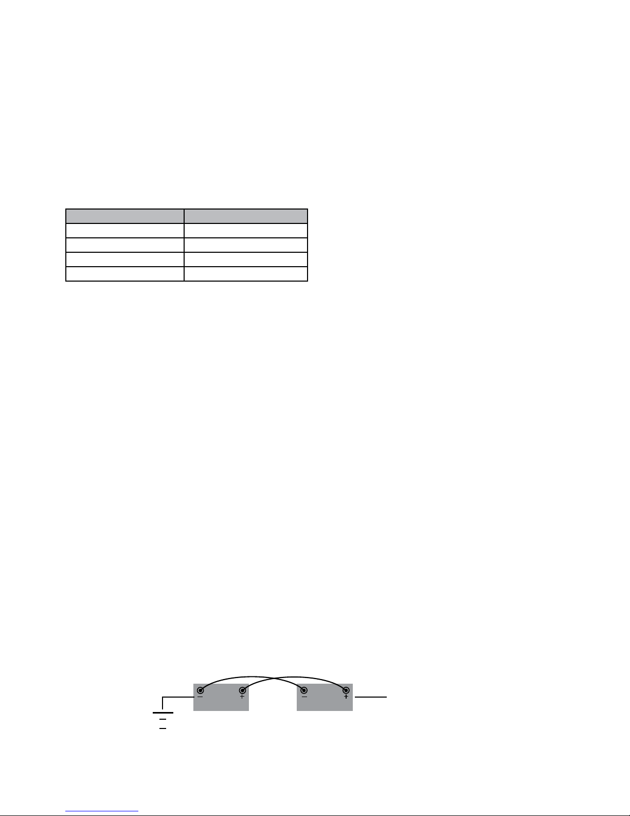
• Overcharging, undercharging, charging or installing in reverse polarity, improper maintenance, allowing the Battery to be deeply discharged via a parasitic load or mishandling
of the Battery such as but not limited to using the terminals for lifting or carrying the Battery. Trickle chargers that do not have a regulated trickle charge voltage between 13.5V
and 13.8V (no lower than 13.5V and no higher than 13.8V) will cause early failure of the Battery. Use of such chargers with the Battery will also void the Battery’s warranty. For
applications where an alternator is present, the alternator must deliver between 14.0V and 14.7V when measured at the Battery’s terminals. Alternators that do not have a
regulated charge between 14.0V and 14.7V (no lower than 14.0V and no higher than 14.7V) will cause early failure of the Battery. Use of such alternators with the Battery will
also void the Battery’s warranty.
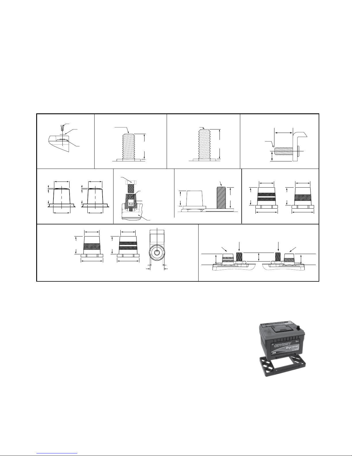
• Failure to properly install the Battery or lack of metal jacket for high temperature or vibration applications.
• Repair or attempted repair of the Battery by anyone other than an authorized Manufacturer’s representative shall void this warranty.
• Normal or accelerated deterioration in the electrical qualities due to operating or application conditions.
• If the Battery is used for an application that requires higher cranking power or a greater reserve rating than the Battery is designed to deliver, or the Battery capacity is less than
the Battery capacity specied by the vehicle manufacturer, or the Battery is otherwise used in applications for which it was not designed.
• Prolonged storage of vehicles with fuel injection computers, alarms, GPS and other electrical devices that require continuous battery power to support active memories; this
power drain must be offset with a maintenance-oat charger, periodic charging or disconnecting the Battery to prevent irreversible damage. A Battery with an open circuit
voltage (OCV) of equal to or less than 8.0V will be deemed as over discharged and void warranty due to misuse and/or neglect.
WARNING - DO NOT USE ANY TYPE OF OIL, ORGANIC SOLVENT, ALCOHOL, DETERGENT, STRONG ACIDS, STRONG ALKALIS, PETROLEUM-BASED SOLVENT
OR AMMONIA SOLUTION TO CLEAN THE BATTERY COVERS AND BATTERY TOPS. THESE MATERIALS MAY CAUSE PERMANENT DAMAGE TO THE BATTERY
COVERS BATTERY TOPS AND WILL VOID THE WARRANTY.
B. To obtain warranty service:
1. Return the Battery to the original supplying wholesaler or dealer.
2. If the Battery is determined by Manufacturer, in its sole discretion, to be defective for material or workmanship under terms of this limited warranty, it will be replaced.
3. Manufacturer’s acceptance of any items shipped to Manufacturer shall not be deemed an admission that the items so shipped are defective. Any items shipped back to
Manufacturer, shall in Manufacturer’s sole discretion, become Manufacturer’s property.
THIS LIMITED WARRANTY IS IN LIEU OF, AND MANUFACTURER DISCLAIMS AND EXCLUDES ALL OTHER WARRANTIES, STATUTORY, EXPRESS OR IMPLIED,
INCLUDING, WITHOUT LIMITATION, ANY WARRANTY OF MERCHANTABILITY OR FITNESS FOR A PARTICULAR PURPOSE. MANUFACTURER’S EXCLUSIVE LIABILITY
FOR BREACH OF WARRANTY SHALL BE TO REPLACE THE BATTERY WITHIN THE EFFECTIVE WARRANTY PERIOD. IN NO EVENT SHALL MANUFACTURER BE LIABLE
FOR ANY LOSS OR DAMAGES OF ANY OTHER KIND, WHETHER DIRECT, INCIDENTAL, CONSEQUENTIAL, EXEMPLARY, SPECIAL OR OTHERWISE. NOR SHALL
MANUFACTURER BE LIABLE FOR ANY REMOVAL OR INSTALLATION EXPENSE, OR THE LOSS OF TIME OR PROFITS.
Some countries and/or states do not allow limitation on how long an implied warranty lasts or the exclusion or limitation of incidental or consequential damages, so the above
limitations may not apply to you. This warranty gives you specic legal rights, which may vary from country to country and/or state to state. This warranty shall be governed by
and interpreted in accordance with the laws of the Commonwealth of Pennsylvania without regard to Pennsylvania conicts of laws rules. The United Nations Convention on
Contracts for the International Sale of Goods signed in Vienna in 1980 shall not apply to this warranty. This warranty is understood to be the exclusive agreement between the
parties relating to the subject matter hereof. No employee or representative of Manufacturer is authorized to make any warranty in addition to those made in this agreement.
Website: www.odysseybattery.com
For your convenience, this space is provided for
attaching your original receipt.
EnerSys EMEA
Löwenstrasse 32
Zürich, Switzerland
Tel: +41 (0) 44 215 74 10
EnerSys World
Headquarters
2366 Bernville Road
Reading, PA 19605
Tel: +1-610-208-1991
+1-800-538-3627
EnerSys Asia
152 Beach Road
Gateway East Building #11-03
Singapore 189721
Tel: +65 6508 1780
Keep your receipt. Receipt is required for longest Warranty Protection.
Publication No. 2602-0232, Rev. 11 - US-ODY-OM-011 - February 2013 - Subject to revisions without prior notice. E.&O.E.
© 2013 EnerSys. All rights reserved.
Trademarks and logos are the property of EnerSys and its affiliates, except General Motors
®
,
which is not the property of EnerSys.

®
Technical Manual
Publication No: US-ODY-TM-001 - April 2011
SEVENTH EDITION

2
®
ODYSSEY®Battery Technical Manual – Seventh Edition
Publication No: US-ODY-TM-001 - April 2011
www.odysseybattery.com
TABLE OF CONTENTS
Introduction 3
Why use ODYSSEY®batteries? 3
Extended discharge characteristics 4
Performance data tables 4
Peukert’s Exponent 11
Cycle Life and Depth of Discharge (DOD) 11
Float Life 12
ODYSSEY®battery storage and deep discharge recovery 12
(A) How do I know the state of charge (SOC) of the battery? 12
(B) How long can the battery be stored? 12
(C) Can the battery recover from abusive storage conditions? 12
(1) German DIN standard test for overdischarge recovery 12
(2) High temperature discharged storage test 13
Parasitic loads 14
Shock, impact and vibration testing 14
(A) Caterpillar™ 100-hour vibration test 14
(B) Shock and vibration test per IEC 61373, Sections 8-10 14
Charging ODYSSEY®batteries 15
(A) Selecting the right charger for your battery 16
(B) Selecting battery type on your charger 16
Rapid charging of ODYSSEY®batteries 17
Load test procedure 17
ODYSSEY®batteries in no-idle applications 18
ODYSSEY®battery PortAlyzer™ Tester 18
Parallel connections 19
Ventilation 19
Concluding remarks 19
Frequently asked SLI battery questions 20
Preface to the Seventh Edition
The addition of new sizes to
the ODYSSEY®battery family of
premium batteries has necessitated
this new edition. Just as in the
previous editions of the battery
guide, detailed performance data
for the new batteries are included
in this revision.
This edition provides an
expanded treatment of the
charging requirements for
ODYSSEY batteries, including
a detailed discussion of a
three-step charge profile that
will bring back a fully discharged
battery in about 6 to 8 hours.
Also discussed are design
variations among chargers
with this profile.
This edition also includes
updated test data on ODYSSEY
batteries.

3
®
Publication No: US-ODY-TM-001 - April 2011
www.odysseybattery.com
INTRODUCTION
The ODYSSEY®battery ingeniously uses absorbed glass mat (AGM) valve regulated lead acid (VRLA) technology to offer, in
one package, the characteristics of two separate batteries. It can deep cycle as well as deliver serious cranking power - it is
like an athlete who is both a champion long distance runner and an excellent sprinter. Traditional battery designs allow them
to either deep cycle or provide high amperage discharges for applications such as engine starting. The ODYSSEY battery
can support applications in either category. ODYSSEY batteries are capable of providing engine cranking pulses of up to
2,250A for 5 seconds at 25ºC (77ºF) as well as deliver 400 charge/discharge cycles to 80% depth of discharge (DOD) when
properly charged. A typical starting, lighting and ignition (SLI) battery, for example, is designed to provide short-duration,
high-amperage pulses; it performs poorly when repeatedly taken down to deep depths of discharge or if they are placed on
a continuous trickle charge, such as when they are used to crank a backup generator. A traditional battery resembles either
a sprinter or a long distance runner; an ODYSSEY battery will do both - provide short duration high amperage pulses or low
rate, long duration drains.
WHY USE ODYSSEY®BATTERIES?
Guaranteed longer service life
With an 8- to 12-year design life in float (emergency power) applications at 25°C (77°F) and a 3- to 10-year service life
depending on the nature of the non-float applications, ODYSSEY batteries save you time and money because you do not have
to replace them as often. Unlike other AGM VRLA batteries, the ODYSSEY battery is capable of delivering up to 400 cycles
when discharged to 80% DOD and properly charged.
Longer storage life
Unlike conventional batteries that need a recharge every 6 to 12 weeks, a fully charged ODYSSEY battery can be stored for
up to 2 years at 25°C (77°F) from a full state of charge. At lower temperatures, storage times will be even longer.
Deep discharge recovery
The ease with which an ODYSSEY battery can recover from a deep discharge is extraordinary. A later section on storage and
recharge criteria discusses test data on this important topic.
Superior cranking and fast charge capability
The cranking power of ODYSSEY batteries is double to triple that of equally sized conventional batteries, even when the
temperature is as low as -40°C (-40ºF). In addition, with simple constant voltage charging there is no need to limit the inrush
current, allowing the battery to be rapidly charged. Please see the section titled Rapid charging of ODYSSEY batteries for
more details on this feature.
Easy shipping
The AGM valve-regulated design of the ODYSSEY battery eliminates the need for vent tubes; further, no battery watering
is required and there is no fear of acid burns or damage to expensive chrome or paint. Because of the starved electrolyte
design, the ODYSSEY battery has been proven to meet the US Department of Transportation (USDOT) criteria for
a non-spillable battery. They can easily ship by highway, air or sea as specified on our MSDS sheet that can be found at
www.odysseybattery.com.
Tough construction
The rugged construction of the ODYSSEY battery makes it suitable for use in a variety of environments ranging from vacuum
to 2 atmospheres (29.4 PSI).
Mounting flexibility
Installing the ODYSSEY battery in any orientation does not affect any performance attribute, except for the PC1800
battery which should be installed right side up. There is also no fear of acid spillage. However, inverted installation is not
recommended.
Superior vibration resistance
ODYSSEY batteries have passed a variety of rigorous tests that demonstrate their ruggedness and exceptional tolerance of
mechanical abuse. Please see the section titled Shock, impact and vibration testing for more details on these tests.
Ready out of the box
ODYSSEY batteries ship from the factory fully charged. If the battery’s open circuit voltage is higher than 12.65V, simply install
it in your vehicle and you are ready to go; if below 12.65V boost charge the battery following the instructions in this manual or
the owner’s manual. For optimum reliability, a boost charge prior to installation is recommended, regardless of the battery’s
open circuit voltage (OCV).

4Publication No: US-ODY-TM-001 - April 2011
www.odysseybattery.com
PC310 & ER8performance data at 25°C, per 12V module
Watts
1000
100
10
1
0.1
0.01 0.1110 100
Hours to 10.02V @ 25˚C (77˚F)
Watts or amps per 12V unit
Amps
2 min 738 80.8 2.7 24.6 613.2 20.4 273.3 9.1
5 min 473 43.2 3.6 39.4 393.3 32.8 175.3 14.6
10 min 312 26.0 4.4 53.1 259.4 44.1 115.6 19.7
15 min 236 19.0 4.8 59.0 196.0 49.0 87.4 21.8
20 min 191 15.0 5.0 62.9 158.4 52.3 70.6 23.3
30 min 139 10.8 5.4 69.3 115.1 57.6 51.3 25.7
45 min 98 7.6 5.7 73.9 81.8 61.4 36.5 27.4
1 hr 76 6.0 6.0 76.4 63.5 63.5 28.3 28.3
2 hr 41 3.2 6.5 81.0 33.7 67.3 15.0 30.0
3 hr 28 2.3 6.8 82.8 22.9 68.8 10.2 30.7
4 hr 21 1.8 7.0 83.7 17.4 69.6 7.8 31.0
5 hr 17 1.4 7.2 84.5 14.0 70.2 6.3 31.3
8 hr 11 0.9 7.6 86.1 8.9 71.5 4.0 31.9
10 hr 9 0.8 7.8 86.8 7.2 72.1 3.2 32.2
20 hr 5 0.4 8.6 90.5 3.8 75.2 1.7 33.5
Time Watts Amps Capacity Energy
(W) (A) (Ah) (Wh) W/liter Wh/liter W/kg Wh/kg
ENERGY AND POWER DENSITIES
ER15 performance data at 25°C, per 12V module
Watts or amps per 12V unit
Hours to 10.02V @ 25˚C (77˚F)
1000
100
10
1
0
0.01 0.1 1 10 100
Watts Amps
Time Watts
(W)
Amps
(A)
Capacity
(Ah)
Energy
(Wh)
ENERGY AND POWER DENSITIES
W/litre Wh/litre W/kg Wh/kg
2 min 1320 127.1 4.2 44.0 612.2 20.4 231.6 7.7
5 min 768 70.7 5.9 64.0 356.2 29.7 134.7 11.2
10 min 485 43.6 7.3 80.9 225.1 37.5 85.2 14.2
15 min 365 32.4 8.1 91.4 169.5 42.4 64.1 16.0
20 min 297 26.1 8.7 99.0 137.8 45.9 52.1 17.4
30 min 220 19.1 9.6 109.8 101.9 50.9 38.5 19.3
45 min 161 13.8 10.4 120.6 74.6 55.9 28.2 21.2
1 hr 128 10.9 10.9 127.8 59.3 59.3 22.4 22.4
2 hr 73 6.1 12.2 145.2 33.7 67.3 12.7 25.5
3 hr 51 4.3 12.9 153.7 23.8 71.3 9.0 27.0
4 hr 40 3.3 13.3 159.6 18.5 74.0 7.0 28.0
5 hr 33 2.7 13.7 163.8 15.2 76.0 5.7 28.7
8 hr 21 1.8 14.4 171.8 10.0 79.7 3.8 30.1
10 hr 18 1.5 14.5 175.2 8.1 81.3 3.1 30.7
20 hr 9 0.8 15.2 183.6 4.3 85.2 1.6 32.2
EXTENDED DISCHARGE CHARACTERISTICS
In addition to its excellent pulse discharge capabilities, the ODYSSEY®battery can deliver many deep discharge cycles,
yet another area where the ODYSSEY battery outperforms a conventional SLI battery, which can deliver only a few deep
discharge cycles.
The following twenty graphs show detailed discharge characteristics of the entire ODYSSEY battery line. The end of discharge
voltage in each case is 10.02V per battery or 1.67 volts per cell (VPC). Each graph shows both constant current (CC)
and constant power (CP) discharge curves at 25ºC (77ºF). The table next to each graph shows the corresponding energy
and power densities. The battery run times extend from 2 minutes to 20 hours.

5
Publication No: US-ODY-TM-001 - April 2011
www.odysseybattery.com
Watts or amps per 12V unit
10000
1000
100
10
1
0.1 0.01 0.1 1 10 100
Hours to 10.02V @ 25˚C (77˚F)
Watts Amps
PC545 & ER20 performance data at 25°C, per 12V module
2 min 1361 128.1 4.3 45.3 680.8 22.7 238.7 8.0
5 min 648 64.4 5.4 54.0 324.2 27.0 113.7 9.5
10 min 415 39.6 6.7 70.6 207.75 35.3 72.8 12.4
15 min 313 29.2 7.3 78.2 156.4 39.1 54.8 13.7
20 min 254 23.5 7.8 83.8 127.0 41.9 44.5 14.7
30 min 187 16.9 8.5 93.3 93.4 46.7 32.7 16.4
45 min 136 12.2 9.2 101.7 67.9 50.9 23.8 17.8
1 hr 107 9.6 9.6 107.4 53.7 53.7 18.8 18.8
2 hr 60 5.3 10.6 120.0 30.0 60.0 10.5 21.1
3 hr 42 3.7 11.1 126.0 21.0 63.1 7.4 22.1
4 hr 32 2.9 11.6 129.6 16.2 64.9 5.7 22.7
5 hr 26 2.3 11.5 132.0 13.2 66.1 4.6 23.2
8 hr 17 1.5 12.0 134.4 8.4 67.25 3.0 23.6
10 hr 14 1.2 12.0 138.0 6.9 69.1 2.4 24.2
20 hr 7 0.7 14.0 144.0 3.6 72.1 1.3 25.3
Time Watts Amps Capacity Energy
(W) (A) (Ah) (Wh) W/liter Wh/liter W/kg Wh/kg
ENERGY AND POWER DENSITIES
PC535 & ER18 performance data at 25°C, per 12V module
Watts or amps per 12V unit
10000
1000
100
10
1
0.1
Watts Amps
Hours to 10.02V @ 25˚C (77˚F)
0.01 0.1 1 10 100
2 min 1182 112.0 3.40 35.5 450.7 13.5 218.9 6.6
5 min 786 71.9 5.75 62.9 299.7 24.0 145.6 11.6
10 min 517.2 46.3 7.90 87.9 197.2 33.5 98.8 16.3
15 min 390.6 34.5 8.60 97.65 148.9 37.2 72.3 18.1
20 min 316.2 27.7 9.10 104.35 120.6 39.8 58.6 19.3
30 min 230.4 20.0 10.0 115.2 87.85 43.9 42.7 21.3
45 min 165 14.2 10.65 123.75 62.9 47.2 30.6 22.9
1 hr 129 11.0 11.0 129.0 49.2 49.2 23.9 23.9
2 hr 70.2 5.9 11.8 140.4 26.8 53.5 13.0 26.0
3 hr 48.5 4.1 12.3 145.4 18.5 55.5 9.0 26.9
4 hr 37.3 3.1 12.4 149.3 14.2 56.9 6.9 27.6
5 hr 30.5 2.5 12.5 152.4 11.6 58.1 5.6 28.2
8 hr 19.9 1.7 13.6 159.4 7.6 60.8 3.7 29.5
10 hr 16.3 1.3 13.0 163.2 6.2 62.2 3.0 30.2
20 hr 9 0.74 14.8 178.8 3.4 68.2 1.7 33.1
Time Watts Amps Capacity Energy
(W) (A) (Ah) (Wh) W/liter Wh/liter W/kg Wh/kg
ENERGY AND POWER DENSITIES
®
10000
1000
100
10
1
0.1
Watts or amps per 12V unit
Hours to 10.02V @ 25˚C (77˚F)
Watts Amps
0.01 0.1 110 100
PC625 & ER22 performance data at 25°C, per 12V module
2 min 1582 154.7 5.20 52.70 536.10 17.90 255.10 8.50
5 min 986 91.6 7.60 82.20 334.35 27.90 159.10 13.30
10 min 635 57.1 9.50 105.90 215.40 35.90 102.50 17.10
15 min 478 42.3 10.60 119.40 161.90 40.50 77.0 19.30
20 min 385 33.8 11.30 128.40 130.60 43.50 62.10 20.70
30 min 281 24.4 12.20 140.70 95.40 47.70 45.40 22.70
45 min 202 17.4 13.05 151.65 68.50 51.40 32.60 24.50
1 hr 159 13.6 13.60 159.0 53.90 53.90 25.65 25.65
2 hr 87 7.3 14.60 174.0 29.50 59.0 14.0 28.10
3 hr 61 5.1 15.30 181.80 20.50 61.60 9.80 29.30
4 hr 47 3.9 15.60 187.20 15.90 63.45 7.55 30.20
5 hr 38 3.2 16.0 192.0 13.0 65.10 6.20 31.0
8 hr 25 2.1 16.80 201.60 8.50 68.30 4.10 32.50
10 hr 20 1.7 17.0 204.0 6.90 69.15 3.30 32.90
20 hr 11 0.9 18.0 216.0 3.70 73.20 1.70 34.80
Time Watts Amps Capacity Energy
(W) (A) (Ah) (Wh) W/liter Wh/liter W/kg Wh/kg
ENERGY AND POWER DENSITIES

6Publication No: US-ODY-TM-001 - April 2011
www.odysseybattery.com
PC925 & ER35 performance data at 25°C, per 12V module
Watts or amps per 12V unit
10000
1000
100
10
1
Watts Amps
0.01 0.1 1 10 100
Hours to 10.02V @ 25˚C (77˚F)
2 min 2381 224.8 7.5 79.3 615.8 20.5 201.8 6.7
5 min 1446 142.8 11.9 120.5 374.0 31.2 122.5 10.2
10 min 954 90.6 15.4 162.2 246.75 42.0 80.9 13.7
15 min 726 67.4 16.9 181.5 187.8 46.9 61.5 15.4
20 min 592 54.2 17.9 195.2 153.0 50.5 50.1 16.5
30 min 436 39.2 19.6 217.8 112.7 56.3 36.9 18.5
45 min 316 28.1 21.1 236.7 81.6 61.2 26.75 20.1
1 hr 250 21.9 21.9 249.6 64.6 64.6 21.2 21.2
2 hr 138 11.9 23.8 276.0 35.7 71.4 11.7 23.4
3 hr 96 8.3 24.9 288.0 24.8 74.5 8.1 24.4
4 hr 74 6.4 25.6 297.6 19.2 77.0 6.3 25.2
5 hr 61 5.2 26.0 303.0 15.7 78.4 5.1 25.7
8 hr 40 3.4 27.2 316.8 10.2 81.9 3.4 26.9
10 hr 32 2.8 27.5 324.0 8.4 83.8 2.75 27.5
20 hr 17 1.5 30.0 348.0 4.5 90.0 1.5 29.5
Time Watts Amps Capacity Energy
(W) (A) (Ah) (Wh) W/liter Wh/liter W/kg Wh/kg
ENERGY AND POWER DENSITIES
1
10
100
1000
10000
Watts or amps per 12V unit
Hours to 10.02V @ 25ºC (77ºF)
0.01 0.1 1 10 100
Watts Amps
ER30 performance data at 25°C, per 12V module
Time Watts
(W)
Amps
(A)
Capacity
(Ah)
Energy
(Wh)
ENERGY AND POWER DENSITIES
W/litre Wh/litre W/kg Wh/kg
2 min 2793.6 268.3 8.9 93.1 755.0 25.2 310.4 10.3
5 min 1744.8 161.3 13.4 145.4 471.6 39.3 193.9 16.2
10 min 1126.2 101.4 16.9 187.7 304.4 50.7 125.1 20.9
15 min 847.8 75.3 18.8 212.0 229.1 57.3 94.2 23.6
20 min 685.8 60.3 20.1 228.6 185.4 61.8 76.2 25.4
30 min 501.6 43.6 21.8 250.8 135.6 67.8 55.7 27.9
45 min 361.8 31.1 23.3 271.4 97.8 73.3 40.2 30.2
1 hr 284.4 24.3 24.3 284.4 76.9 76.9 31.6 31.6
2 hr 156.6 13.2 26.4 313.2 42.3 84.6 17.4 34.8
3 hr 109.8 9.2 27.6 329.4 29.7 89.0 12.2 36.6
4 hr 84.6 7.1 28.4 338.4 22.9 91.5 9.4 37.6
5 hr 69.6 5.8 29.0 348.0 18.8 94.1 7.7 38.7
8 hr 45.6 3.8 30.4 364.8 12.3 98.6 5.1 40.5
10 hr 37.2 3.2 32.0 372.0 10.1 100.5 4.1 41.3
20 hr 20.4 1.7 34.0 408.0 5.5 110.3 2.3 45.3
PC680 & ER25 performance data at 25°C, per 12V module
Watts or amps per 12V unit
10000
1000
100
10
1
0.1
Watts Amps
Hours to 10.02V @ 25˚C (77˚F)
0.01 0.1 1 10 100
2 min 1486 143.0 4.8 49.5 601.4 20.0 212.3 7.1
5 min 792 78.8 6.6 66.0 320.5 26.7 113.1 9.4
10 min 512 49.3 8.4 87.1 207.3 35.25 73.2 12.4
15 min 389 36.7 9.2 97.4 157.6 39.4 55.6 13.9
20 min 318 29.6 9.8 104.9 128.7 42.5 45.4 15.0
30 min 236 21.6 10.8 118.2 95.7 47.8 33.8 16.9
45 min 173 15.6 11.7 130.1 70.2 52.6 24.8 18.6
1 hr 138 12.3 12.3 138.0 55.8 55.8 19.7 19.7
2 hr 79 6.9 13.8 157.2 31.8 63.6 11.2 22.5
3 hr 56 4.8 14.4 166.5 22.5 67.4 7.9 23.8
4 hr 43 3.7 14.8 172.8 17.5 69.9 6.2 24.7
5 hr 35 3.0 15.0 177.0 14.3 71.6 5.1 25.3
8 hr 23 2.0 16.0 187.2 9.5 75.75 3.3 26.7
10 hr 19 1.6 16.0 192.0 7.8 77.7 2.7 27.4
20 hr 10 0.8 16.0 204.0 4.1 82.6 1.5 29.1
Time Watts Amps Capacity Energy
(W) (A) (Ah) (Wh) W/liter Wh/liter W/kg Wh/kg
ENERGY AND POWER DENSITIES

7
Publication No: US-ODY-TM-001 - April 2011
www.odysseybattery.com
®
ER40 performance data at 25°C, per 12V module
Watts or amps per 12V unit
Hours to 10.02V @ 25˚C (77˚F)
0.01 0.1 1 10 100
1000
100
10
1
0.1
Watts Amps
Time Watts
(W)
Amps
(A)
Capacity
(Ah)
Energy
(Wh)
ENERGY AND POWER DENSITIES
W/litre Wh/litre W/kg Wh/kg
2 min 3307.2 326.8 10.9 110.2 668.1 22.3 264.6 8.8
5 min 2332.8 219.5 18.3 194.4 471.3 39.3 186.6 15.6
10 min 1575.0 143.2 23.9 262.5 318.2 53.0 126.0 21.0
15 min 1200.0 107.2 26.8 300.0 242.4 60.6 96.0 24.0
20 min 974.4 86.1 28.7 324.8 196.8 65.6 78.0 26.0
30 min 713.4 62.0 31.0 356.7 144.1 72.1 57.1 28.5
45 min 513.0 44.0 33.0 384.8 103.6 77.7 41.0 30.8
1 hr 402.6 34.3 34.3 402.6 81.3 81.3 32.2 32.2
2 hr 220.8 18.5 37.0 441.6 44.6 89.2 17.7 35.3
3 hr 154.2 12.9 38.7 462.6 31.2 93.5 12.3 37.0
4 hr 120.0 10.0 40.0 480.0 24.2 97.0 9.6 38.4
5 hr 99.0 8.2 41.0 495.0 20.0 100.0 7.9 39.6
8 hr 66.0 5.5 44.0 528.0 13.3 106.7 5.3 42.2
10 hr 55.2 4.6 46.0 552.0 11.2 111.5 4.4 44.2
20 hr 32.4 2.7 54.0 648.0 6.5 130.9 2.6 51.8
PC1200 performance data at 25°C, per 12V module
Watts or amps per 12V unit
Watts Amps
Hours to 10.02V @ 25˚C (77˚F)
0.01 0.1 1 10 100
10000
1000
100
10
1
2 min 3580 337.9 11.3 119.2 613.0 20.4 205.8 6.9
5 min 1992 199.1 16.6 165.9 341.1 28.4 114.5 9.5
10 min 1338 127.9 21.7 227.5 229.1 38.9 76.9 13.1
15 min 1026 96.0 24.0 256.5 175.7 43.9 59.0 14.7
20 min 840 77.5 25.6 277.2 143.8 47.5 48.3 15.9
30 min 624 56.6 28.3 312.0 106.8 53.4 35.9 17.9
45 min 458 40.8 30.6 343.4 78.4 58.8 26.3 19.7
1 hr 364 32.1 32.1 363.6 62.25 62.25 20.9 20.9
2 hr 203 17.7 35.4 406.8 34.8 69.7 11.7 23.4
3 hr 143 12.3 36.9 428.4 24.5 73.4 8.2 24.6
4 hr 110 9.5 38.0 441.6 18.9 75.6 6.3 25.4
5 hr 91 7.7 38.5 453.0 15.5 77.6 5.2 26.0
8 hr 59 5.0 40.0 475.2 10.2 81.4 3.4 27.3
10 hr 48 4.1 41.0 480.0 8.2 82.2 2.8 27.6
20 hr 25 2.2 44.0 504.0 4.3 86.3 1.5 29.0
Time Watts Amps Capacity Energy
(W) (A) (Ah) (Wh) W/liter Wh/liter W/kg Wh/kg
ENERGY AND POWER DENSITIES
Time Watts
(W)
Amps
(A)
Capacity
(Ah)
Energy
(Wh)
ENERGY AND POWER DENSITIES
W/litre Wh/litre W/kg Wh/kg
2 min 3982 384.3 12.8 132.7 396.6 13.2 192.4 6.4
5 min 2846 264.8 22.1 237.2 283.5 23.6 137.5 11.5
10 min 1993 180.8 30.1 332.1 198.5 33.1 96.3 16.0
15 min 1561 139.7 34.9 390.3 155.5 38.9 75.4 18.9
20 min 1294 114.8 38.3 431.4 128.9 43.0 62.5 20.8
30 min 976 85.5 42.8 487.9 97.2 48.6 47.1 23.6
45 min 722 62.6 46.9 541.2 71.9 53.9 34.9 26.1
1 hr 577 49.7 49.7 576.6 57.4 57.4 27.9 27.9
2 hr 326 27.7 55.4 652.1 32.5 64.9 15.8 31.5
3 hr 230 19.4 58.3 689.8 22.9 68.7 11.1 33.3
4 hr 179 15.0 60.1 714.0 17.8 71.1 8.6 34.5
5 hr 146 12.3 61.5 731.6 14.6 72.9 7.1 35.3
8 hr 96 8.0 64.2 766.2 9.5 76.3 4.6 37.0
10 hr 78 6.5 65.5 782.0 7.8 77.9 3.8 37.8
20 hr 42 3.5 69.9 832.1 4.1 82.9 2.0 40.2
Watts or amps per 12V unit
Hours to 10.02V @ 25ºC (77ºF)
Watts Amps
0.01 0.1 1 10 100
10000
1000
100
10
1
PC1220 performance data at 25°C, per 12V module

Time Watts
(W)
Amps
(A)
Capacity
(Ah)
Energy
(Wh)
ENERGY AND POWER DENSITIES
W/litre Wh/litre W/kg Wh/kg
2 min 5477.3 527.2 17.6 182.6 438.2 14.6 199.9 6.7
5 min 3758.2 349.4 29.1 313.2 300.7 25.1 137.2 11.4
10 min 2601.6 235.8 39.3 433.6 208.1 34.7 94.9 15.8
15 min 2037.0 182.0 45.5 509.3 163.0 40.7 74.3 18.6
20 min 1691.9 149.8 49.9 564.0 135.4 45.1 61.7 20.6
30 min 1282.0 112.1 56.0 641.0 102.6 51.3 46.8 23.4
45 min 955.0 82.5 61.9 716.2 76.4 57.3 34.9 26.1
1 hr 767.6 65.8 65.8 767.6 61.4 61.4 28.0 28.0
2 hr 440.8 37.3 74.5 881.7 35.3 70.5 16.1 32.2
3 hr 313.6 26.4 79.1 940.8 25.1 75.3 11.4 34.3
4 hr 244.8 20.5 82.0 979.2 19.6 78.3 8.9 35.7
5 hr 201.4 16.8 84.2 1006.9 16.1 80.5 7.3 36.7
8 hr 132.5 11.1 88.5 1059.8 10.6 84.8 4.8 38.7
10 hr 108.3 9.0 90.5 1082.7 8.7 86.6 4.0 39.5
20 hr 57.3 4.8 96.5 1146.8 4.6 91.7 2.1 41.9
PC1350 performance data at 25°C, per 12V module
1
10
100
1000
10000
0.01 0.10 1 10
Watts or amps per 12V unit
Hours to 10.02V @ 25ºC (77ºF)
100
Watts Amps
Time Watts
(W)
Amps
(A)
Capacity
(Ah)
Energy
(Wh)
ENERGY AND POWER DENSITIES
W/litre Wh/litre W/kg Wh/kg
2 min 5308.3 499.5 16.5 175.2 576.1 19.0 233.8 7.7
5 min 3439.7 315.8 26.2 285.5 373.3 31.0 151.5 12.6
10 min 2261.4 203.0 33.9 377.7 245.4 41.0 99.6 16.6
15 min 1715.5 151.9 38.0 428.9 186.2 46.5 75.6 18.9
20 min 1393.0 122.2 40.7 463.9 151.2 50.3 61.4 20.4
30 min 1022.9 88.6 44.3 511.5 111.0 55.5 45.1 22.5
45 min 739.4 63.3 47.4 554.5 80.2 60.2 32.6 24.4
1 hr 582.5 49.4 49.4 582.5 63.2 63.2 25.7 25.7
2 hr 320.6 26.8 53.6 641.2 34.8 69.6 14.1 28.2
3 hr 223.7 18.6 55.7 671.0 24.3 72.8 9.9 29.6
4 hr 172.6 14.3 57.2 690.5 18.7 74.9 7.6 30.4
5 hr 141.1 11.7 58.4 705.4 15.3 76.5 6.2 31.1
8 hr 92.1 7.6 61.0 736.6 10.0 79.9 4.1 32.4
10 hr 75.2 6.2 62.5 751.9 8.2 81.6 3.3 33.1
20 hr 40.3 3.4 67.9 805.5 4.4 87.4 1.8 35.5
25-PC1400 & 35-PC1400 performance data at 25°C,
per 12V module
1
10
100
1000
10000
0.01 0.1 1 10
Watts or amps per 12V unit
Hours to 10.02V @ 25ºC (77ºF)
Watts Amps
100
8Publication No: US-ODY-TM-001 - April 2011
www.odysseybattery.com
Time Watts
(W)
Amps
(A)
Capacity
(Ah)
Energy
(Wh)
ENERGY AND POWER DENSITIES
W/litre Wh/litre W/kg Wh/kg
2 min 4561.7 432.9 14.3 150.5 531.5 17.5 221.4 7.3
5 min 2936.3 266.5 22.1 243.7 342.1 28.4 142.5 11.8
10 min 1919.1 169.6 28.3 320.5 223.6 37.3 93.2 15.6
15 min 1451.2 126.6 31.7 362.8 169.1 42.3 70.4 17.6
20 min 1176.0 101.8 33.9 391.6 137.0 45.6 57.1 19.0
30 min 861.5 73.8 36.9 430.8 100.4 50.2 41.8 20.9
45 min 621.9 52.8 39.6 466.4 72.5 54.3 30.2 22.6
1 hr 489.8 41.4 41.4 489.8 57.1 57.1 23.8 23.8
2 hr 270.1 22.6 45.3 540.2 31.5 62.9 13.1 26.2
3 hr 189.0 15.8 47.4 567.1 22.0 66.1 9.2 27.5
4 hr 146.4 12.2 48.8 585.7 17.1 68.2 7.1 28.4
5 hr 120.1 10.0 50.0 600.6 14.0 70.0 5.8 29.2
8 hr 79.2 6.6 52.7 633.2 9.2 73.8 3.8 30.7
10 hr 65.0 5.4 54.1 650.1 7.6 75.7 3.2 31.6
20 hr 35.7 3.0 59.4 713.5 4.2 83.1 1.7 34.6
75-PC1230 & 75/86-PC1230 performance data at 25°C,
per 12V module
1
10
100
1000
10000
0.01 0.1 1 10
Watts or amps per 12V unit
Hours to 10.02V @ 25ºC (77ºF)
100
Watts Amps

34-PC1500, 34R-PC1500, 34M-PC1500, 34/78-PC1500 &
78-PC1500 performance data at 25°C, per 12V module
Watts or amps per 12V unit
10000
1000
100
10
1
Watts Amps
0.01 0.1 1 10 100
Hours to 10.02V @ 25˚C (77˚F)
2 min 5228 494.8 16.3 172.5 538.1 17.8 209.9 6.9
5 min 3337 304.4 25.3 277.0 343.5 28.5 134.0 11.1
10 min 2175 193.6 32.3 363.3 223.9 37.4 87.4 14.6
15 min 1644 144.5 36.1 411.0 169.2 42.3 66.0 16.5
20 min 1332 116.1 38.7 443.7 137.2 45.7 53.5 17.8
30 min 977 84.2 42.1 488.4 100.5 50.3 39.2 19.6
45 min 706 60.3 45.2 529.3 72.6 54.5 28.3 21.3
1 hr 556 47.3 47.3 556.2 57.3 57.3 22.3 22.3
2 hr 307 25.9 51.7 615.0 31.7 63.3 12.3 24.7
3 hr 215 18.1 54.2 646.5 22.2 66.5 8.7 26.0
4 hr 167 14.0 56.0 668.4 17.2 68.8 6.7 26.8
5 hr 137 11.5 57.4 685.4 14.1 70.6 5.5 27.5
8 hr 90 7.6 60.6 723.1 9.3 74.4 3.6 29.0
10 hr 74 6.2 62.3 742.5 7.6 76.4 3.0 29.8
20 hr 41 3.25 65.0 814.0 4.2 83.8 1.6 32.7
Time Watts Amps Capacity Energy
(W) (A) (Ah) (Wh) W/liter Wh/liter W/kg Wh/kg
ENERGY AND POWER DENSITIES
9
Publication No: US-ODY-TM-001 - April 2011
www.odysseybattery.com
Watts or amps per 12V unit
10000
1000
100
10
1
Hours to 10.02V @ 25˚C (77˚F)
Watts Amps
0.01 0.1 1 10 100
PC1700 performance data at 25°C, per 12V module
2 min 5942 569.8 19.0 197.9 607.0 20.2 215.3 7.2
5 min 3636 337.6 28.1 279.9 343.3 28.6 121.7 10.1
10 min 2411 218.5 37.2 384.5 231.1 39.3 82.0 13.9
15 min 1833 163.8 41.0 433.5 177.2 44.3 62.8 15.7
20 min 1490 132.6 43.7 467.3 144.7 47.7 51.3 16.9
30 min 1091 96.0 48.0 522.0 106.7 53.3 37.8 18.9
45 min 786 68.6 51.4 567.0 77.2 57.9 27.4 20.5
1 hr 615 53.6 53.6 594.6 60.75 60.75 21.5 21.5
2 hr 333 28.9 57.8 648.0 33.1 66.2 11.7 23.5
3 hr 229 19.9 59.6 671.4 22.9 68.6 8.1 24.3
4 hr 175 15.2 61.0 684.0 17.5 69.9 6.2 24.8
5 hr 142 12.4 61.8 693.0 14.2 70.8 5.0 25.1
8 hr 90 8.0 63.6 705.6 9.0 72.1 3.2 25.6
10 hr 73 6.5 64.5 714.0 7.3 72.9 2.6 25.9
20 hr 37 3.4 67.9 732.0 3.7 74.8 1.3 26.5
Time Watts Amps Capacity Energy
(W) (A) (Ah) (Wh) W/liter Wh/liter W/kg Wh/kg
ENERGY AND POWER DENSITIES
1
10
100
1000
10000
0.01 0.1 1 10
Watts or amps per 12V unit
Hours to 10.02V @ 25ºC (77ºF)
Watts Amps
100
65-PC1750 performance data at 25°C, per 12V module
Time Watts
(W)
Amps
(A)
Capacity
(Ah)
Energy
(Wh)
ENERGY AND POWER DENSITIES
W/litre Wh/litre W/kg Wh/kg
2 min 5890.3 565.9 18.7 194.4 567.9 18.7 224.0 7.4
5 min 3769.7 334.2 27.7 312.9 363.5 30.2 143.3 11.9
10 min 2439.6 210.9 35.2 407.4 235.2 39.3 92.8 15.5
15 min 1832.0 157.7 39.4 458.0 176.6 44.2 69.7 17.4
20 min 1477.1 127.2 42.4 491.9 142.4 47.4 56.2 18.7
30 min 1075.8 93.0 46.5 537.9 103.7 51.9 40.9 20.5
45 min 770.8 67.2 50.4 578.1 74.3 55.7 29.3 22.0
1 hr 604.6 53.0 53.0 604.6 58.2 58.3 23.0 23.0
2 hr 354.6 29.4 58.9 709.2 34.2 68.4 13.5 27.0
3 hr 252.0 20.7 62.0 756.0 24.3 72.9 9.6 28.7
4 hr 196.3 16.0 64.1 785.0 18.9 75.7 7.5 29.8
5 hr 160.9 13.1 65.7 804.6 15.5 77.6 6.1 30.6
8 hr 104.8 8.6 69.1 838.5 10.1 80.9 4.0 31.9
10 hr 85.0 7.1 70.6 850.3 8.2 82.0 3.2 32.3
20 hr 45.6 3.8 75.7 912.6 4.4 88.0 1.7 34.7

10 Publication No: US-ODY-TM-001 - April 2011
www.odysseybattery.com
1
10
100
1000
10000
0.01 0.1 1 10
Watts or amps per 12V unit
Hours to 10.02V @ 25ºC (77ºF)
Watts Amps
100
31-PC2150 & 31M-PC2150 performance data at 25°C,
per 12V module
Watts or amps per 12V unit
10000
1000
100
10
1
Watts Amps
Hours to 10.02V @ 25˚C (77˚F)
0.01 0.1110 100
PC2250 performance data at 25°C, per 12V module
2 min 7090 671.6 22.4 236.1 1143.0 14.75 181.8 6.1
5 min 4820 443.8 37.0 401.5 301.2 25.1 123.6 10.3
10 min 3291 296.4 50.4 559.5 205.6 35.0 84.4 14.4
15 min 2553 227.1 56.8 638.3 159.5 39.9 65.5 16.4
20 min 2107 185.8 61.3 695.3 131.7 43.5 54.0 17.8
30 min 1583 137.9 69.0 791.5 98.9 49.5 40.6 20.3
45 min 1170 100.9 75.7 877.5 73.1 54.8 30.0 22.5
1 hr 937 80.2 80.2 937.0 58.6 58.6 24.0 24.0
2 hr 536 45.2 90.4 1072.0 33.5 67.0 13.7 27.5
3 hr 382 32.0 96.0 1146.0 23.9 71.6 9.8 29.4
4 hr 299 25.0 100.0 1196.0 18.7 74.7 7.7 30.7
5 hr 247 20.6 103.0 1235.0 15.4 77.2 6.3 31.7
8 hr 165 13.8 110.4 1320.0 10.3 82.5 4.2 33.9
10 hr 137 11.4 114.0 1370.0 8.6 85.6 3.5 35.1
20 hr 76 6.3 126.0 1520.0 4.75 95.0 2.0 39.0
Time Watts Amps Capacity Energy
(W) (A) (Ah) (Wh) W/liter Wh/liter W/kg Wh/kg
ENERGY AND POWER DENSITIES
PC1800-FT performance data at 25°C, per 12V module
Time Watts
(W)
Amps
(A)
Capacity
(Ah)
Energy
(Wh)
ENERGY AND POWER DENSITIES
W/liter Wh/liter W/kg Wh/Kg
2 min 4422 491.4 16.4 147.4 199.6 6.7 73.7 2.5
5 min 4422 491.2 40.9 368.5 199.6 16.6 73.7 6.1
10 min 4422 454.7 75.8 737.0 199.6 33.3 73.7 12.3
15 min 3984 373.3 93.3 996.0 179.8 44.9 66.4 16.6
20 min 3384 312.7 104.2 1128.0 152.7 50.9 56.4 18.8
30 min 2610 238.3 119.2 1305.0 117.8 58.9 43.5 21.8
45 min 1968 177.8 133.4 1476.0 88.8 66.6 32.8 24.6
1 hr 1590 143.1 143.1 1590.0 71.8 71.8 26.5 26.5
2 hr 936 82.2 164.4 1872.0 42.2 84.5 15.6 31.2
3 hr 666 58.3 174.9 1998.0 30.1 90.2 11.1 33.3
4 hr 522 45.4 181.6 2088.0 23.6 94.2 8.7 34.8
5 hr 426 37.3 186.5 2130.0 19.2 96.1 7.1 35.5
8 hr 282 24.6 196.8 2256.0 12.7 101.8 4.7 37.6
10 hr 234 20.2 202.0 2340.0 10.6 105.6 3.9 39.0
20 hr 126 10.9 218.0 2520.0 5.7 113.7 2.1 42.0
1
10
100
1000
10000
0.01 0.10 1 10
Watts or amps per 12V unit
Hours to 10.02V @ 25ºC (77ºF)
100
Watts Amps
Time Watts
(W)
Amps
(A)
Capacity
(Ah)
Energy
(Wh)
ENERGY AND POWER DENSITIES
W/liter Wh/liter W/kg Wh/Kg
2 min 7025 678.5 22.4 231.8 515.3 17.0 199.0 6.6
5 min 4740 438.5 36.4 393.4 347.7 28.9 134.3 11.1
10 min 3176 285.9 47.7 530.4 233.0 38.9 90.0 15.0
15 min 2428 215.5 53.9 607.0 178.1 44.5 68.8 17.2
20 min 1980 174.1 58.0 659.2 145.2 48.4 56.1 18.7
30 min 1460 127.0 63.5 730.0 107.1 53.5 41.4 20.7
45 min 1059 91.2 68.4 793.9 77.6 58.2 30.0 22.5
1 hr 835 71.5 71.5 835.2 61.3 61.3 23.7 23.7
2 hr 461 39.0 78.0 922.2 33.8 67.7 13.1 26.1
3 hr 322 27.1 81.4 966.8 23.6 70.9 9.1 27.4
4 hr 249 20.9 83.8 996.8 18.3 73.1 7.1 28.2
5 hr 204 17.1 85.6 1020.0 15.0 74.8 5.8 28.9
8 hr 134 11.2 89.7 1070.4 9.8 78.5 3.8 30.3
10 hr 110 9.2 91.9 1095.9 8.0 80.4 3.1 31.0
20 hr 60 5.0 100.3 1191.9 4.4 87.4 1.7 33.8

11
Publication No: US-ODY-TM-001 - April 2011
www.odysseybattery.com
®
PEUKERT’S EXPONENT
The capacity of a battery depends on the rate at which it
is discharged. For example, the ODYSSEY®31-PC2150
battery is rated at 92Ah when discharged at the 10-hour
rate (9.2A for 10 hours) and 100Ah when discharged at the
20-hour rate (5.0A for 20 hours). This variability in battery
capacity makes it problematic to estimate the support time
one can expect for a given current draw. This is where the
Peukert equation, shown below comes in handy.
Capacity = Inx t
log T2– log T1
n = ------------------––––––
log I1– log I2
In the first equation, nis called the Peukert’s coefficient;
I1and I2are two discharge current rates and T1and T2are
the corresponding discharge durations. Knowing the rated
capacity of the battery and the coefficient (given in the table
below) one can use this equation to estimate the battery
support time for a given amp draw.
Suppose you have a 15A load you want to run off the
ODYSSEY 31-PC2150 battery, which is rated at 92Ah and
you want to know approximately how long it will support
the load. From the table below, nis 1.112 for the Group 31
battery; its capacity is 92Ah and I is 15A. Substituting these
values into the Peukert equation yields a support time t of
about 4-1/2 hours before the battery is fully depleted.
Table 1
Some battery monitoring systems (BMS) offer the option
of entering the Peukert coefficient so that the BMS can
estimate the time left for the battery to be fully discharged
at a given discharge rate. If you have such a system, you
can use the table above to find the value of your battery
model. An important point to keep in mind here is that this
estimation is valid only for an ambient temperature
of 25°C (77°F).
CYCLE LIFE AND DEPTH OF
DISCHARGE (DOD)
Applications in which the battery is frequently discharged
and recharged are called cyclic. A complete cycle starts with
a charged battery that is discharged and then brought back
to a full charge. Battery life in these applications is stated as
the number of cycles the battery will deliver before its capacity
drops to 80% of its rated value. For example, suppose a
battery is rated at 100 amp-hours (Ah) and has a published
cycle life of 400. This means that the battery can be cycled
400 times before its delivered capacity drops to 80Ah.
Proper charging and DOD are the two key factors that
determine how many cycles a battery will deliver before it
reaches end of life. The DOD is simply the ratio of capacity
extracted from the battery to its rated capacity expressed
as a percentage. If a 100Ah battery delivers 65Ah and then
recharged it is said to have delivered a 65% DOD cycle.
The relationship between DOD and cycle life for ODYSSEY
batteries is shown in Figure 1. The lower the DOD the higher
the number of cycles the battery will deliver before reaching
end of life.
Figure 1
The true dual purpose design of ODYSSEY batteries
is reflected in the cycle life results shown in the graph
below. The two ODYSSEY 65-PC1750 battery samples
were discharged at 25A (the reserve capacity rate) for 108
minutes (80% of 135 minutes, which is the 100% rate for this
battery), rested for an hour then charged for 5 hours at 14.7V
with a 50A current limit. Since five hours are not sufficient to
charge them completely, both batteries were given 20-hour
charges every ten cycles. Sample 1 cycled 581 times and
Sample 2 lasted 544 cycles before reaching end of life.
100
1000
10000
100000
1000000
Number of cycles
Depth of discharge, DOD %
Charge profile: Full recharge at 14.7V with a 1C current limit
ODYSSEY®
Battery Model
Peukert
Coefficient
ODYSSEY®
Battery Model
Peukert
Coefficient
PC310 1.072 PC1350 1.147
PC535 1.078 25-PC1400
(all variations) 1.034
PC545 1.107 34-PC1500
(all variations) 1.133
PC625 1.107 PC1700 1.091
PC680 1.129 65-PC1750 1.081
PC925 1.100 PC1800-FT 1.150
PC1200 1.106 31-PC2150
(all variations) 1.112
PC1220 1.132 PC2250 1.180
75-PC1230
(all variations) 1.074
0
20
40
60
80
100
120
140
0 50 100 150 200 250 300 350 400 450 500 550 600 650
Run Time in Minutes
Cycle
End of Life -
Sample 1 - Cycle 581 /Sample 2 - Cycle 544

12 Publication No: US-ODY-TM-001 - April 2011
www.odysseybattery.com
FLOAT LIFE
Float life refers to the life expectancy of a battery that is used
primarily as a source of backup or emergency power. Emergency
lighting, security alarm and uninterruptible power systems (UPS)
are good examples of batteries in float applications. In each of
these applications the battery is discharged only if the main utility
power is lost; otherwise the battery remains on continuous trickle
charge (also called float charge).
Since ODYSSEY®batteries are dual purpose by design, they
offer a long-life battery option in float applications. At room
temperature (77°F or 25°C) these batteries have a design life of
10+ years in float applications; at end of life an ODYSSEY battery
will still deliver 80% of its rated capacity.
Heat is a killer of valve regulated lead acid (VRLA) absorbed
glass mat (AGM) batteries such as ODYSSEY batteries and
the rule of thumb that relates battery temperature to battery
life is that for every 8°C rise in battery temperature, the float life
is cut in half. This means that an ODYSSEY battery that has a
10-year float life at 25°C (77°F) will have only a 5-year life at 33°C
(91°F) and a 2-1/2 year float life at 41°C (106°F). Therefore if
your float application requires batteries to be in an uncontrolled
temperature environment you should account for battery life that
will be shorter than its design life at 25°C (77°F).
ODYSSEY®BATTERY STORAGE
AND DEEP DISCHARGE RECOVERY
For any rechargeable battery, storage and recharge are
important criteria. This section provides some guidelines that
will help you get the most from your ODYSSEY battery.
(A) How do I know the state of charge (SOC) of the battery?
Use Figure 2 to determine the SOC of the ODYSSEY battery,
as long as the battery has not been charged or discharged
for six or more hours. The only tool needed is a good quality
digital voltmeter to measure its open circuit voltage (OCV)1.
The graph shows that a healthy, fully charged ODYSSEY
battery will have an OCV of 12.84V or higher at 25ºC (77ºF).
Figure 2: Open circuit voltage and state of charge
(B) How long can the battery be stored?
The graph below shows the shelf life of the ODYSSEY battery
at different temperatures. At 25°C (77ºF), these batteries can
be stored for up to 2 years. The lower the temperature, the
longer the storage time. Charge the battery before storing it.
The effect of temperature on storage is evident. Roughly,
every 10°C (18°F) increase in temperature cuts the storage
time in half. Thus, at 35°C (95°F) the battery may be stored
for only 1 year before a recharge becomes necessary.
Figure 3 applies only to batteries that are fully charged before
storage.
Figure 3: ODYSSEY®battery storage time at temperatures
(C) Can the battery recover from abusive storage
conditions?
Yes, the ODYSSEY battery can recover from extremely deep
discharges as the following test results demonstrate.
(1) German DIN standard test for overdischarge recovery
In this test, a PC925 was discharged over 20 hours (0.05C10
rate)2to 10.20V. After the discharge2a 5Ωresistor was
placed across the battery terminals and the battery kept in
storage for 28 days.
At the end of the storage period, the battery was charged
at 13.5V for only 48 hours. A second 0.05C10 discharge
yielded 97% of rated capacity, indicating that a low rate
48-hour charge after such a deep discharge was insufficient;
however, the intent of the test is to determine if the battery
is recoverable from extremely deep discharges using only
a standby float charger. A standard automotive charger at
14.4V would have allowed the battery to recover greater than
97% of its capacity.
These test results prove that ODYSSEY batteries can recover
from abusive storage conditions. Reinforcing this conclusion
is the next test, which is even harsher than the DIN standard
test, because in this test the battery was stored in a
discharged state at a temperature of 50°C (122°F).
State of Charge (SOC), %
Open circuit voltage (OCV), V
10 20 30 40 50 60 70 80 90 100
13.0
12.8
12.6
12.4
12.2
12.0
11.8
11.6
12.84V or higher indicates 100% SOC
Open circuit storage time in weeks
Percent of 0.05C capacity
10 20 30 40 50 60 70
80
90
100
0
70
30
40
60
50
25C 45C 65C
1The OCV of a battery is the voltage measured between its positive and negative terminals without the battery connected to an external
circuit (load). It is very important to take OCV reading only when the battery has been off charge for at least 6-8 hours, preferably overnight.
2The C10 rate of charge or discharge current in amperes is numerically equal to the rated capacity of a battery in ampere-hours
at the 10-hour rate. Thus, a 26Ah battery at the 10-hour rate, such as the PC925 would have a C10 rate of 2.6A.
Other manuals for PC310
7
This manual suits for next models
26
Table of contents
Other Odyssey Batteries Pack manuals
Popular Batteries Pack manuals by other brands

Narada
Narada 12REXC70 Operation manual

GivEnergy
GivEnergy Giv-Bat8.2 Installation and user manual

Busa
Busa BSP MAX II PM-X00-710 instruction manual

EnerSys
EnerSys PerfectRail DS Operation and maintenance instructions

Hobbico
Hobbico Life Source instruction manual

Hoppecke
Hoppecke sun powerpack classic5.5/24 Installation and operating manual