manuals.online logo
Brands
  1. Home
  2. •
  3. Brands
  4. •
  5. Eaton
  6. •
  7. Batteries Pack
  8. •
  9. Eaton EBPLED7W User manual

Eaton EBPLED7W User manual

IB505009EN
Instructions for Surelites LED Emergency Battery Packs
Includes the following model numbers: EBPLED7W, EBPLED14W
WARNING
Risk of Electric Shock
Disconnect power at fuse or circuit breaker before
installing or servicing.
WARNING
Risk of Fire/Electric Shock
If not qualified, consult an electrician.
Important Safeguards
WHEN USING ELECTRICAL EQUIPMENT, BASIC SAFETY
PRECAUTIONS SHOULD ALWAYS BE OBSERVED INCLUDING
THE FOLLOWING.
1. READ AND FOLLOW ALL SAFETY INSTRUCTIONS
2. Do not use outdoors.
3. Do not mount near gas or electric heaters
4. Equipment should be mounted in locations and at adequate
heights to prevent tampering by unauthorized personnel.
5. The use of accessory equipment not recommended by
Eaton may cause an unsafe condition and will void the
warranty.
6. Do not use this equipment for other than its intended
purpose.
7. Not for use with sealed and gasketed fixtures
8. SAVE THESE INSTRUCTIONS
NOTES
1. To prevent voltage from being present on the output wires
(Red/White & Blue/White), do not connect the test button
assembly to the EBP or insure the EZ key is securely in
place.
2. This product is for use with LED fixtures that have LED
loads capable of the output wattage and that have LED
forward voltage within the ranges below.
Output Power (W) Min Vf (V) Max Vf (V)
All 7 Watt
Versions 7 8 55
All 14 Watt
Versions 14 16 55
3. Make sure all of the connections are in accordance with
the National Electrical Code and any local regulations.
4. To reduce the risk of electrical shock, disconnect both
normal and emergency power supplies and the test button
indicator light (which disconnects the battery) before
servicing. Insuring the battery disconnect is securely in
place also prevents battery powered operation.
5. These emergency ballasts can be field or factory installed
depending on version. See mounting section for details.
6. This product is for use in indoor fixtures only. Do NOT
use near heated air handling outlets, wet locations or
hazardous locations.
7. An un-switched AC power source is required. (120 - 277
volts 50/60 HZ) for proper operation.
8. Do not attempt to service the battery. The sealed,
no-maintenance battery is not field replaceable. Contact
the manufacturer for information on service.
9. All maintenance should be performed by qualified service
personnel.
FEATURES
This emergency battery pack (EBP) includes extra features
which enhance its operation and maintainability.
1. Patented EZ key battery disconnect: When the EZ key is
inserted into the test button, the battery is disconnected.
This feature prevents unnecessary cycling of the battery
during the construction process. It can also be used if the
room is decommissioned for an extended period of time to
prevent the batteries from being over discharged.
2. Patent pending Test Button / Indicator Light / Laser Input:
The test button houses the EZ key, powers the indicator
light, contains the laser input for testing and functions as
the mechanical test button. Integration of these functions
improves performance and fixture aesthetics.
Sure-Lites
CONTAINS NICKEL-CADMIUM
RECHARGEABLEBATTERY.
MUST BE RECYCLEDOR
DISPOSED OF PROPERLY. Ni -Cd
For use in
temperature rating
0°C to 55°C
EBPLED Class 2 Output
3. Power controlled output: This feature maintains consistent
light output during the entire 90 minutes of emergency
operation ensuring there is no drop in lumen output as the
battery voltage drops.
Field Installation Classification (EBPLED7W, EBPLED14W)
1. Determine electrical compatability with fixture: Verify the
emergency driver wattage (7 watts or 14 watts depending
on model) does not exceed the drivers AC input. Also, verify
that the forward voltage of the LEDs are within the operating
parameters of the selected model (see table below).
Output Power (W) Min Vf (V) Max Vf (V)
EBPLED7W 7 8 55
EBPLED14W 14 16 55
2. Calculate Lumen output during emergency operation:
Go to the website www.designlights.org and identify the
light fixture by using the available search criteria. Determine
the fixture rated data – efficacy in lumens/watt. Multiply
the fixture efficacy by the output wattage of the selected
emergency battery pack to determine the lumen output of
the fixture during emergency operation.
Example: Fixture efficacy = 100 lumens/watt
EBPLED7W provides 7 watts of constant power
(Use 14W for EBPLED14W)
Fixture output = 100 lumens/watt X 7 watts = 700
lumens during emergency operation
3. Insure means of egress lighting levels: Follow industry
standard methods of lighting layout to determine placement
of emergency battery pack equipped fixtures. Verify the
selected EBP will provide sufficient lumen output to meet
path of egress illumination requirements.
INSTALLATION
1. Mounting The EBP can be mounted inside a fixture channel,
on the back of a fixture, or near the fixture. The flex conduit
should be connected to a junction enclosure which allows
access to the wiring connections for grounding.
(Note: EBP assemblies without conduit must be factory
installed in the wireway of the fixture).
2. Wiring Refer to the block diagram below for the wiring of the
LED load, AC driver, and AC power.
The unswitched AC power for the EBP and the power for the
AC driver should be from the same branch circuit to prevent
disconnecting 2 sources of power and the battery during
servicing.
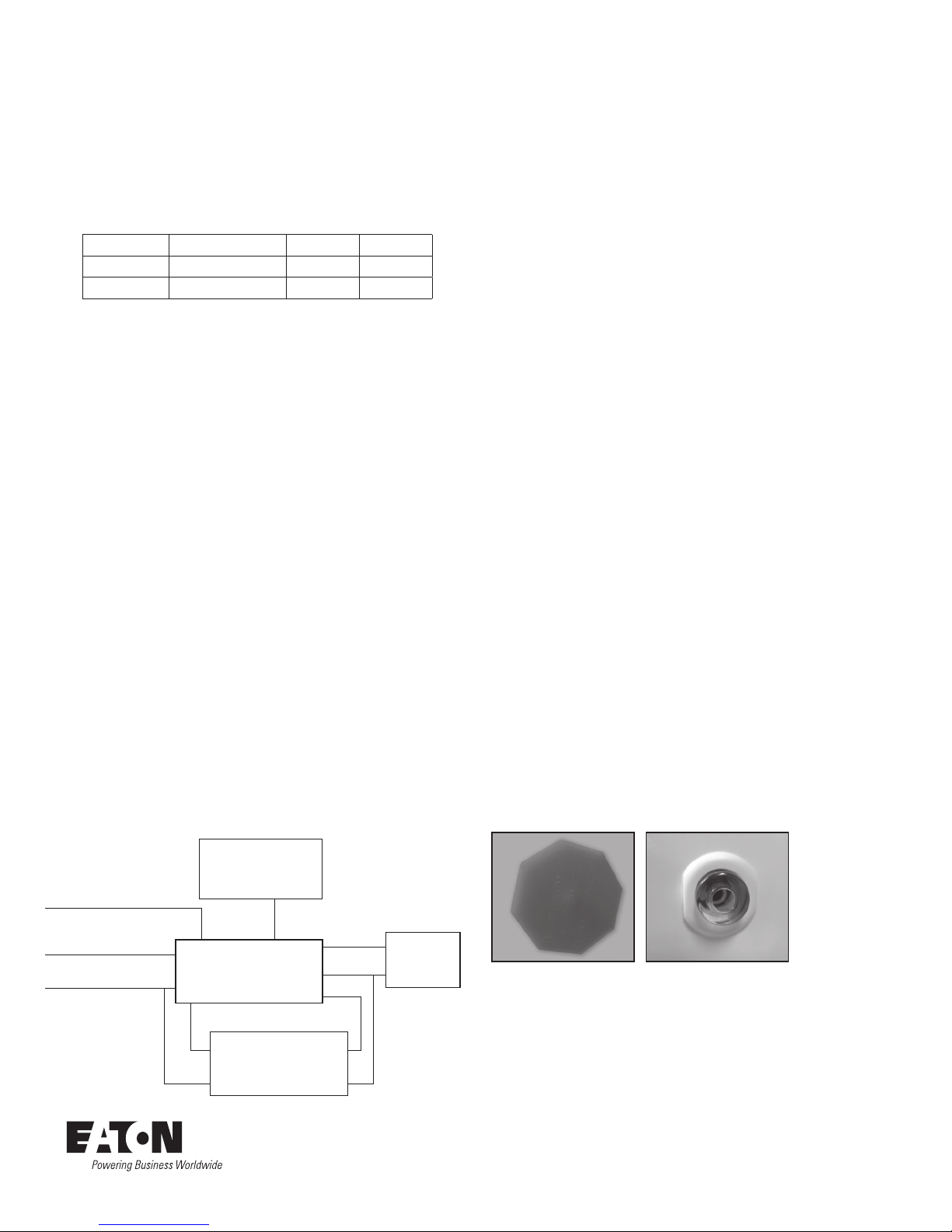
3. Mounting the Test Button / Indicator Light / Laser Input
Mount the Test Button / Indicator Light / Laser Input so the
indicator light is visible once the fixture is installed. Proper
mounting is required for accessibility and functionality of the
laser input testing feature and EZ key battery disconnect.
OPERATION
Once AC power is permanently applied to the blue wire of the
fixture remove the EZ key and store it for later use. When AC
power is applied, the charging indicator light is illuminated,
indicating the battery is being charged. When the power fails,
the emergency ballast automatically switches to emergency
power, operating its LED load at the rated output for at least 90
minutes.
NOTE: The battery is not fully charged until 24 hours after the
AC power is applied.
MAINTENANCE
Although no routine maintenance is required to keep the
emergency LED driver functional, it should be checked
periodically to verify proper operation. Follow any applicable
local or national codes. The following schedule is the minimum
required to meet NFPA 101 standards:
1. Visually inspect that the charging light is illuminated
monthly.
2. Test the emergency operation of the fixture monthly for a
minimum of 30 seconds. Perform the test by pressing the
test button / indicator light for 30 seconds or aiming a laser
pointer at the clear test button.The LED load should operate
at the rated output.
(Note: The laser test will not trigger if the ambient light is
too high. The light must be switched off in fixtures where the
test button is in close proximity to the light, or the test will
need to be triggered mechanically)
3. Conduct a 90 minute discharge test annually by
disconnecting the unswitched power. The LED load should
operate at the rated output for at least 90 minutes.
4. Keep written records of testing
Refer any service requirements indicated by these
checks to qualified personnel.
WARRANTIES AND LIMITATION OF LIABILITY
Please refer to www.eaton.com/LightingWarrantyTerms for our
terms and conditions.
Image of Test Button / Indicator Light / Laser Input
With Battery Disconnected (Left)
Without Battery Disconnected (Right)
Eaton
1121 Highway 74 South
Peachtree City, GA 30269
eaton.com/lighting
© 2015 Eaton
All Rights Reserved
Printed in USA
Publication No. IB505009EN
Eaton is a registered trademark.
All trademarks are property
of their respective owners.
Test Button /
Indicator Light /
Laser Input /
Battery Disconnect
Emergency Driver
EBPLED
LED Load
AC Driver
Outside of fixture color is WHT
120-277VAC Neutral WHT
Outside of fixture color is BLK
Power for AC Driver WHT/BLK
WHT/BLK
Plenum
Wire
RED/WHT
BLU/WHT
RED
Outside of fixture color is BLU
Unswitched 120-277VAC
50/60 Hz BLK/ORG L
L +
+
N
N -
-
Block Diagram of
wiring for EBPLED

This manual suits for next models

1

Other Eaton Batteries Pack manuals

Eaton Powerware 5125 Two-in-One EBM User manual

Eaton

Eaton Powerware 5125 Two-in-One EBM User manual

Eaton 9PX User manual

Eaton

Eaton 9PX User manual

Eaton Powerware 5125 User manual

Eaton

Eaton Powerware 5125 User manual

Eaton Metalux User manual

Eaton

Eaton Metalux User manual

Eaton PWHR1234W2FR User manual

Eaton

Eaton PWHR1234W2FR User manual

Popular Batteries Pack manuals by other brands

Huawei LUNA2000 Series user manual

Huawei

Huawei LUNA2000 Series user manual

Auber Instruments Auber AUB manual

Auber Instruments

Auber Instruments Auber AUB manual

SunSynk SUN-BATT-15.97 manual

SunSynk

SunSynk SUN-BATT-15.97 manual

Ryobi RB18L50 Original instructions

Ryobi

Ryobi RB18L50 Original instructions

Phonic BP-RG user manual

Phonic

Phonic BP-RG user manual

Sartorius YRB11Z operating instructions

Sartorius

Sartorius YRB11Z operating instructions

RHOX BAT-48100-01 Operator's manual

RHOX

RHOX BAT-48100-01 Operator's manual

Weco HeSU 4k4 PRO instruction manual

Weco

Weco HeSU 4k4 PRO instruction manual

ASL INTERCOM BPC65 product manual

ASL INTERCOM

ASL INTERCOM BPC65 product manual

Nikon MB-D12 user manual

Nikon

Nikon MB-D12 user manual

Celestron ThermoCharge user manual

Celestron

Celestron ThermoCharge user manual

TheSunPays BALI48 user manual

TheSunPays

TheSunPays BALI48 user manual

solarwatt flex AC-1 1.3 quick start guide

solarwatt

solarwatt flex AC-1 1.3 quick start guide

Gogen PB 60001 WP user guide

Gogen

Gogen PB 60001 WP user guide

Lipper Curt installation manual

Lipper

Lipper Curt installation manual

Master Battery UPOWER Ecoline UE-24Li100 manual

Master Battery

Master Battery UPOWER Ecoline UE-24Li100 manual

ResMed Power Station II user guide

ResMed

ResMed Power Station II user guide

Sanyo Denki SANUPS E11A102 Series Battery Replacement Procedure

Sanyo Denki

Sanyo Denki SANUPS E11A102 Series Battery Replacement Procedure

manuals.online logo
manuals.online logoBrands
  • About & Mission
  • Contact us
  • Privacy Policy
  • Terms and Conditions

Copyright 2025 Manuals.Online. All Rights Reserved.