ELGO Electronic IZ15E User manual

Operation Manual
SERIES IZ15E
Battery powered Length measuring System
Battery powered Length measuring SystemBattery powered Length measuring System
Battery powered Length measuring System
Predestined for the mobile assembly on manual sledges, carriage and back
stop systems
Battery powered indicator
LCD Display

-
2
-
1.
General Information ....................................................................................................... 3
1.1.
Information Operation Manual ......................................................................................... 3
1.2.
Explanation of Symbols ..................................................................................................... 3
1.3.
Statement of Warranties ................................................................................................... 4
1.4.
Demounting and Disposal ................................................................................................
2.
Safety .............................................................................................................................. 6
2.1.
General Cause of Risks ..................................................................................................... 6
2.2.
Personal Protective Equipment .......................................................................................... 6
2.3.
Conventional Use ............................................................................................................. 7
3.
Transport and Storage ................................................................................................... 7
3.1.
Safety Instructions for Transport/Unpacking and Loading .................................................. 7
3.2.
Handling of Packaging Material ........................................................................................ 7
3.3.
Check of Transport ........................................................................................................... 8
3.4.
Storage ............................................................................................................................ 8
.
Product Features ............................................................................................................. 9
5.
Technical Data .............................................................................................................. 10
.1.
Dimensions .................................................................................................................... 10
.1.1 Dimensions Indicator .......................................................................................................... 10
.1.2 Dimensions Sensor ............................................................................................................. 10
.1.3 Accessories ....................................................................................................................... 11
.1.3.1 IZ1 E-000-3-XX.X-0 ................................................................................................. 11
.1.3.2 Battery Sets for IZ1 E-000-3-XX.X-0 ........................................................................ 12
.1.3.3 IZ1 E-000-4-XX.X-0 ................................................................................................. 13
.2 Technical Data .................................................................................................................. 14
6.
Installation .................................................................................................................... 15
6.1.
Qualifications of the Staff ............................................................................................... 1
6.2.
Description of the assembly / Installation ........................................................................ 1
6.3 The Sensor ........................................................................................................................ 1
7.
Structure and Function .................................................................................................. 16
7.1.
Selecting parameters and input ...................................................................................... 16
7.1.1 Parameter level activate ...................................................................................................... 16
7.1.2 Accessing the Decade ........................................................................................................ 16
7.1.3 Change the value .............................................................................................................. 16
7.1.4 Sign .................................................................................................................................. 16
7.1. Leaving Parameter level ...................................................................................................... 16
7.1.6 Parameters ........................................................................................................................ 17
7.2.
Default Parameter / Calibration ...................................................................................... 18
7.2.1 Calibration ........................................................................................................................ 18
7.2.2 Loading the Default Parameter ............................................................................................ 18
7.3 Functions in Normal mode ................................................................................................ 19
7.3.1 Set datum value ................................................................................................................. 19
7.3.2 Switching incremental / absolute ......................................................................................... 19
7.3.3 Activate offsets ................................................................................................................... 19
7.3.
Accessories ..................................................................................................................... 20
7.3.1 Magnetic tape ................................................................................................................... 20
8.
Interferences ................................................................................................................. 21
8.1.
Security .......................................................................................................................... 21
8.1
Electrical interference suppression .................................................................................. 22
8.2
Restart after fault clearance ............................................................................................ 22
8.3
EMC information ............................................................................................................ 23
9.
Maintenance ................................................................................................................. 23
10.
Type Designation .......................................................................................................... 2
11.
Accessories .................................................................................................................... 2
12.
Register ......................................................................................................................... 25
12.1.
Index .............................................................................................................................. 2
Content

-
3
-
1. General Information
1.1. Information Operation Manual
The manual contains important information regarding the handling of the indicator.
Precondition for safe operation is the compliance with the specified safety and handling instructions.
Moreover, observe the existing local accident prevention regulation and general safety rules.
Please read the operation manual carefully before starting to work. The manual should be kept accessible at
anytime. The illustrations in the manual are for better representation of the facts they are not necessarily to
scale and can be slightly different to the actual construction.
1.2. Explanation of Symbols
Warning notices
Warning noticesWarning notices
Warning notices
Warning notices are characterised by symbols in the operation manual.
The notes will be introduced by signal words to express the magnitude of the danger.
Follow these advices in order to avoid accidents and injuries to persons and property.
DANGER!
DANGER!DANGER!
DANGER!
... adverts to direct dangerous situations that can lead to death or severe injuries.
CAUTION!
CAUTION!CAUTION!
CAUTION!
... advices to potentially dangerous situations that can lead to death or severe
injuries.
ATTANTION!
ATTANTION!ATTANTION!
ATTANTION!
... advices to potentially dangerous situations that can lead to damages on
property.
General Information

-
4
-
Hints and commendations
Hints and commendationsHints and commendations
Hints and commendations
ADVERT!
ADVERT!ADVERT!
ADVERT!
...highlights helpful hints and recommendations for efficient and failure-free
operation.
Specific safety instructions
Specific safety instructionsSpecific safety instructions
Specific safety instructions
The following symbols in conjunction with safety instructions are used in order to point out possible hazards:
DANGER!
DANGER!DANGER!
DANGER!
...marks perilous situations by electricity. By non-observance of the safety
instructions the possibilities of death or severe injuries exist. The operations have to
be carried out only by an electrician.
1.3. Statement of Warranties
The warranty conditions are in a separate document.
Guarantee
GuaranteeGuarantee
Guarantee
The producer guarantees the functional capability of the process engineering and the selected parameter.
The period of warranty is one year and begins with the date of delivery.
General Information

-
-
1.4. Demounting and Disposal
Unless otherwise authorized, dispose the item considering the safety instructions.
Before demounting
Before demountingBefore demounting
Before demounting
Disconnect the power supply
Secure against re-start
Disconnect supply lines physically and discharge remaining energy
Dispose operating supplies with respect to the environment
Disposal
DisposalDisposal
Disposal
Recycle the decomposed elements:
Scrap metal elements
Recycle plastic parts
Dispose the rest of the components according to their material consistence
ATTENTION!
ATTENTION!ATTENTION!
ATTENTION!
Wrong disposal damage caused to the environment!
Electronic waste, electronic components, lubricants and operating supplies are
liable to treatment of hazardous waste.
Only approved specialized companies should perform disposal.
Local authorities and waste management facilities provide information about environmentally suitable
disposal.
General Information

-
6
-
2. Safety
2.1. General Cause of Risks
This chapter gives an overview about all important safety aspects to guarantee an optimal protection of
employees.
Non-observance of the instructions mentioned in this operation manual can result in hazardous situations.
2.2. Personal Protective Equipment
Employees should wear protective clothing during installation of the device to minimize the risk of accidents.
Therefore:
Change into protective clothing before beginning the work process. Also observe any labels in the operating
area regarding protective clothing.
Protective clothing
Protective clothing Protective clothing
Protective clothing
Safety workin
Safety workinSafety workin
Safety workin
g clothing
g clothingg clothing
g clothing
... is close-fitting
... is tear proof
... has tight sleeves without distant parts
Also wear no rings, necklaces or other jewellery.
Also wear no rings, necklaces or other jewellery.Also wear no rings, necklaces or other jewellery.
Also wear no rings, necklaces or other jewellery.
Protective gloves
Protective glovesProtective gloves
Protective gloves
... for protecting the hands against abrasion and cuts
Safety

-
7
-
2.3. Conventional Use
The indicator IZ15 is for the limited purpose as described in this manual:
The indicator IZ15 is constructed for positioning uses only.
CAUTION!
CAUTION!CAUTION!
CAUTION!
Danger through non-conventional use!
Non-intended use and non-observance of this operation manual can lead to dangerous
situations.
Therefore:
Use IZ15 only as described
Strictly follow this manual
Avoid in particular:
Remodelling, refitting or changing of the device or parts of it with the intention to alter
functionality or scope of the position indicator.
ELGO is not liable for any damages resulting from improper use of the product.
3. Transport and Storage
3.1. Safety Instructions for Transport/Unpacking and Loading
ATTENTION!
ATTENTION!ATTENTION!
ATTENTION!
Professional transport only.
Do not throw, hit or fold the package.
3.2. Handling of Packaging Material
Adverts for proper disposal refer to 1.4.
Conventional use
, Transport,
Storage

-
8
-
3.3. Check of Transport
Examine delivery immediately after receiving for completeness and transport damages.
In case of externally recognizable transport damages:
Do not accept the delivery or do accept under reserve
Note extent of damages on the transportation documents or on the delivery note
File complaint immediately
ADVERT!
ADVERT!ADVERT!
ADVERT!
Claim any damages you recognize as soon as possible. The claims for damage must be
filed in the lawful reclaim periods.
3.4. Storage
Store device only under following conditions:
Do not store outside
Keep dry and dust-free
Do not expose to aggressive media
Protect from direct sun light
Avoid mechanical shocks
Storage temperature: 20 to + 0 °C
Relative humidity: 60% non-condensing
Inspect packages regularly if stored for an extensive period of time (> 3 months)
T
ransport,
Storage

-
9
-
. Product Features
The length measuring system IZ15 is a combination of a magnetic sensor, which has a cable (0.1 ... 2m
lengths) with a display device. Therefore, no wiring or connections are necessary.
The IZ15 is particularly suitable for mounting on the sledge and stop moving systems, cause no cable need
to be carried.
In order to be able to measure along the way a magnetic strip is glued (ELGO MB20-2 -10-1-R, 2. mm
Pole pitch) in respect of which the sensor the necessary information (current position) returns. The sensor
head is with its high-class protection against any kind of dust, dirt and water jets and absolutely wear-
resistant. The distance to the magnetic tape to the sensor may be up to 0.8 mm.
The display has extensive programming (including pulse, temperature, decimal places, Counting, chain level
and set function, adjustable reference value and a switch for mm-inch or operation).
The resolution of the magnetic sensor is 0.1 mm. Its maximum speed is 2. m / s.
Product features
-
10
-
5. Technical Data
.1. Dimensions
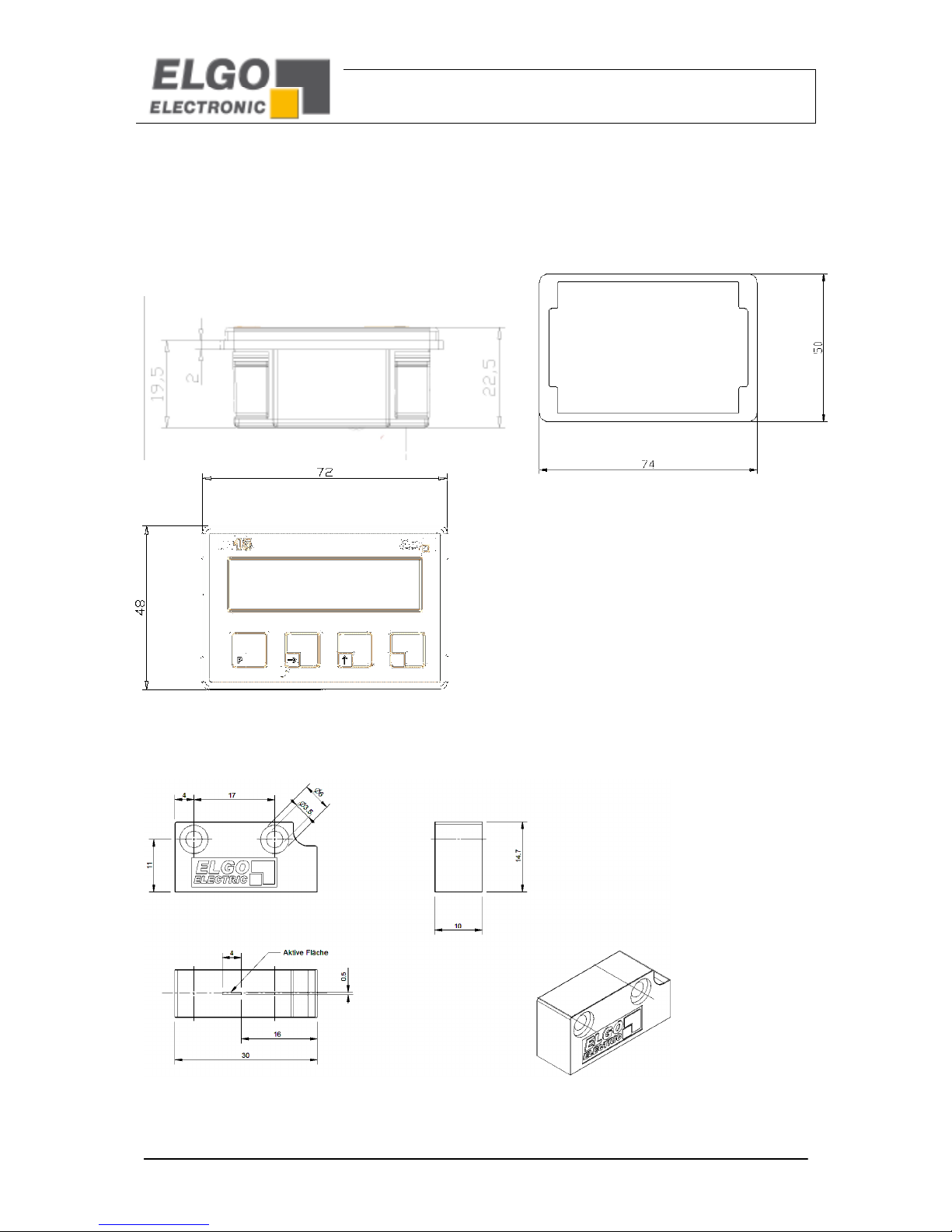
5.1.1 Dimensions Indicator
5.1.2 Dimensions Sensor
Seal
SealSeal
Seal
Technical
Dat
a

-
11
-
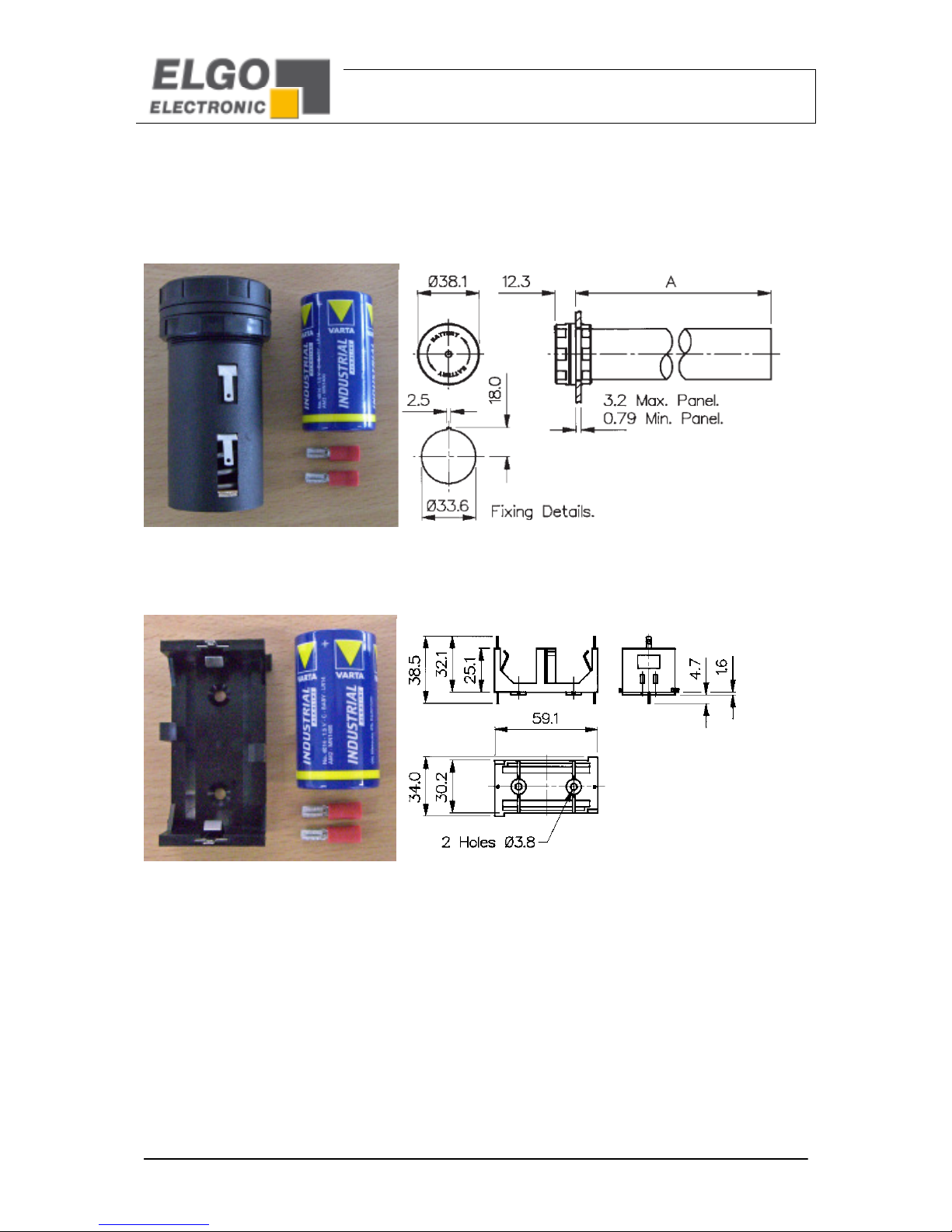
5.1.3 Accessories
5.1.3.1 IZ15E-000-3-XX.X-0
Version with standard cable outlet
• Display with external sensor (fixed cable outlet)
• standard sensor cable length: 1.0 m
• supply via cable outlet (Length: 200m) for external battery compartment (not included, available as
accessory
Technical
Dat
a
-
12
-
5.1.3.2 Battery Sets for IZ15E-000-3-XX.X-0
a) „Battery - Set 1xC Installation“
b) „Battery - Set 1xC Open“
Technical
Dat
a

-
13
-
5.1.3.3 IZ15E-000- -XX.X-0
• Display with external sensor (fixed cable outlet)
• standard sensor cable length: 1.0 m
• supply of Type 2AA battery compartment on the back (batteries are included)

-
14
-
.2 Technical Data
* e.g.: 1 x Battery Type C or Type D ( 1, V)
2 x Battery Type AAA / AA / C / D ( 3,0 V)
Display IZ15
LCD-Display 7 Decades (Digit height 9mm)
Power supply
Status of
Battery and Unit
1 x Battery (1, V) or 2 x Battery ( 3V) *
Consumption with encoder < 1 mA at 1, V
Operation temperature + ° up to + 0 ° C
Drive speed max. 2, m/sec
Housing Material: Plastic, black
Housing dimensions W x H x D = 72 x 48 x 23 mm
Installation depth 30 mm (incl. cable)
Front panel outbreak
W
x H = 68 x 4 mm
Protection class
IP 43 (
installed)
Magnetic Sensor MS20.25
Sensor cable length 0,1 m up to max. 2,0 m (more on request)
Resolution 0,1mm
Protection class IP66 Zinc die cast
Operation temperature + ° up to + 0° C
min.
Radius to bend
min. 60 mm
Distance
Sensor/
Tape
max. 0,8 mm (
without cover tape
„C“)
Magnetic Tape MB 20-25-10-1-R
Operation temperature
0° up to
+ 0°C
Accuracy at
20° C in mm
+/
-
(0,02 + 0,02 x L) L = effe
c
tive
Measuring length
in m
Length expansion coefficient = 16 x 10-6 x 1/K
Technical
Dat
a

-
1
-
6. Installation
6.1. Qualifications of the Staff
Improper maintenance
... can lead to serious personal injuries or property
damage.
Therefore:
Maintenance work should be referred to qualified
and authorized by the operator and instructed
personnel.
6.2. Description of the assembly / Installation
The lock of the device in the front panel made four lateral clips. Using a simple angle plate is also an
assembly possibility. The device IZ1 comes with a seal. This is necessary to guarantee spray- and dust
protection.
6.3 The Sensor
The sensor integrates the magneto resistance test bridges from which, addicted to the track, the counts for
the signal processing electronic are formed. The distance between the sensor and band within the range X
may not be larger than 1.0 mm. Each smaller value is permitted. The sensor cable has 6 cores and is highly
flexible. The cores are stranded in pairs and shielded. The sensor cable can be used in a dragline.
Installation

-
16
-
7. Structure and Function
7.1. Selecting parameters and input
7.1.1 Parameter level activate
F
P
For 3 seconds / 1 each x then press
With this key the parameter level will be activated. After about 3 seconds, the display shows "P 01" for the
first parameter. When you press the button again, the parameter value can be changed. In that way all
available parameters can be successive selected.
7.1.2 Accessing the Decade
Set
1x press
With this button the Decade will be forwarded at 1 point from the left to the right. The selected Decade is
blinking.
7.1.3 Change the value
1x press
With this button the value of the selected decade will be increased at 1 (0…9 or 0…1).
7.1. Sign
*
1x press
With this button you can adjust at some parameters the sign (+/-)
7.1.5 Leaving Parameter level
Hold for 3 seconds in the parameter level
All parameters will be stored while leaving this level.
Structure
and
Function

-
17
-
7.1.6 Parameters
Parameter
ParameterParameter
Parameter
Descripti
DescriptiDescripti
Descripti
on
onon
on
Default Parameters
Default ParametersDefault Parameters
Default Parameters
P01: A
Counting direction
:
A = 0: positive
A = 1: negative
0
P02: A
mm / inch
Switching
A = 0: mm – Mode
A = 1: Inch – Mode (Resolution 0,001 Inch )
0
P03: A
Decimal poin
t ( 0 ... 3 )
1
P0 : ABC
Key lock
:
A: Button „ SET “ ( 0 = active / 1 = not active)
B: Button„ Incr / Abs „ ( 0 = active / 1 = not active)
C: Button„ * “ ( 0 = active / 1 = not active)
000
P08:
Multipli
c
ation
fa
c
tor (0,0001 ... 9,9999 )
1,0000
P09:
Referen
ce value
(
-
999999,9 ... + 99999
9,9 )
0,0
P10:
Offset
1 (
-
999999,9 ... + 999999,9 )
0,0
P11:
Offset
2 (
-
999999,9 ... + 999999,9 )
0,0
P12:
Offset
3 (
-
999999,9 ... + 999999,9 )
0,0
P99:
Displays the
Firmware
–
Version
X.XX
Structure
and
Function

-
18
-
7.2. Default Parameter / Calibration
7.2.1 Calibration
(The Sensor must be installed on the Magnetic tape!)
Switch off the unit.
F
P
press this button
While pressing this button switch the unit on again
Here, the calibration of the sensor is triggered and "CAL 0" is shown in the display. Now, move the sensor
slowly in one direction on the tape. After the calibration (display "CAL 0"… "CAL 4") is the display again in
normal mode.
7.2.2 Loading the Default Parameter
(The Sensor must be installed on the Magnetic tape!)
Switch off the unit.
press this button
While pressing this button switch the unit on again
Here, all parameters will be reset to default parameters. Also herewith the calibration of the sensor is
triggered and "CAL 0" is shown in the display. Now, move the sensor slowly in one direction on the tape.
After the calibration (display "CAL 0"… "CAL 4") is the display again in normal mode.
Structure
and
Function

-
19
-
7.3 Functions in Normal mode
7.3.1 Set datum value
F
P
and
Set
1x press together
With this key combination the actual value will be set to the reference value. (Only in the ABS-mode possible,
if no offset level is activated.) The reference value is entered in parameter P09.
7.3.2 Switching incremental / absolute
1x press
With this key the unit switch from absolute mode to incremental mode:
The display value is set to zero, and display the symbol "INC". Pressing the button again the display set again
into absolute mode and “abs” is shown again.
7.3.3 Activate offsets
*
1x press
This button activates the three adjustable offsets. Herewith an offset will be added to the actual shown value
(Only in the ABS mode possible). The activation of an offset will be displayed by the symbols , or
. The offsets will be set in the parameters P10, P11 and P12.
Structure
and
Functi
on

-
20
-
7.3. Accessories
7.3.1 Magnetic tape
The magnetic tape MB 20
MB 20MB 20
MB 20-
--
-2
22
2 -
--
-10
1010
10-
--
-1
11
1-
--
-R
RR
R
The magnetic tape consists of 3 components:
available lengths 0,5 - 32 m
1,8mm
C A B
Befestigungsseite
Sensorseite
L
10mm
Structure
and
Function
Sensor
s
ide
Installation side
Table of contents


