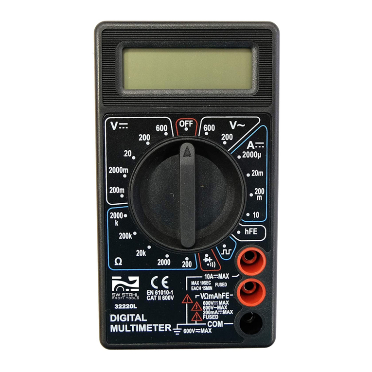
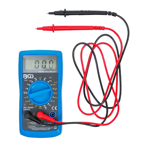
BGS technic 63400 User manual

SW-Stahl und Werkzeugvertriebs GmbH Tel. +49 (0) 2191 / 46438-0
F56essartSresukreveL ax +49 (0) 2191 / 46438-40
ed.lhatsws@ofni:liaM-EdiehcsmeR79824-D
Instruction Manual
BGS technic KG
Bandwirkerstr. 3
42929 Wermelskirchen
Tel.: 02196 720480
Fax.: 02196 7204820
www.bgstechnic.com
© BGS technic KG, Copying and further use not allowed
Art. 63400
Digital Multimeter
WARRANTY
This instrument is warranted to be free from defects in material and workmanship. Any instrument
found defective within two years from the delivery date and returned to the factory with transportation
charges prepaid, will be repaired, adjusted, or replaced at no Charge to the original purchaser. This
warranty does not cover expandable items such as batteries or fuses. If the defect has been caused
by a misuse or abnormal Operation conditions, the guarantee does not apply.
SAFETY INFORMATION
The multimeter has been designed according to IEC-61010 concerning electronic measuring
instruments with a measurement category (CATII 250V) .
ELECTRICAL SYMBOLS
Alternating Current
Direct Current
Caution, risk of danger, refer to
the operating manual before use.
Caution, risk of electric shock.
Earth (ground) Terminal
Fuse
Conforms to European Union directives
The equipment is protected throughout by double insulation or reinforced insulation.

SW-Stahl und Werkzeugvertriebs GmbH Tel. +49 (0) 2191 / 46438-0
F56essartSresukreveL ax +49 (0) 2191 / 46438-40
ed.lhatsws@ofni:liaM-EdiehcsmeR79824-D
Instruction Manual
BGS technic KG
Bandwirkerstr. 3
42929 Wermelskirchen
Tel.: 02196 720480
Fax.: 02196 7204820
www.bgstechnic.com
© BGS technic KG, Copying and further use not allowed
WARNING
To avoid possible electric shock or personal injury, follow these guidelines:
1. Do not use the meter if it is damaged. Before you use the meter, inspect the case. Pay particular
attention to the insulation surrounding the connectors,
2. Inspect the test leads for damaged insulation or exposed metal. Check the test leads for
continuity. Replace damaged test leads before you use the
meter.
3. Do not use the meter if it operates abnormally. Protection may be impaired. When in doubt, have
the meter serviced.
4. Do not operate the meter around explosive gas, vapor, or dust.
5. Do not apply more than the rated voltage, as marked on the meter, between terminals or between
any terminal and earth ground.
6. Before use, verify the meters Operation by measuring a known voltage.
7. When measuring current, turn off circuit power before connecting the meter in the circuit.
8. Remember to place the meter in series with the circuit.
9. When servicing the meter, use only specified replacement parts.
10. Use with caution when working above 30V ac rms, 42V peak, or 60V de.
11. Such voltages pose a shock hazard.
12. When using the probes, keep your fingers behind the finger guards on the probes.
13. Connect the common test lead before you connect the live test lead.
14. When you disconnect test leads, disconnect the live test lead first.
15. Remove the test leads from the meter before you open the case.
16. Do not operate the meter with the cover removed or loosened.
17. To avoid false readings, which could lead to possible electric shock or personal injury, replace the
battery as soon as the low battery indicator appears.
18. Remaining endangerment:
When an input terminal is connected to dangerous live potential it is to be noted that this
potential at all other terminals can occur!
19. CATII-Measurement Category II is for measurements performed on circuits directly connected to
low voltage installation. Do not use the meter for measurements within Measurement Categories
IM and IV.
CAUTION
To avoid possible damage to the meter or to the equipment under test, follow these guidelines:
Disconnect circuit power and discharge all capacitors before testing resistance, continuity, diode
and temperature.
Use the proper terminals, function, and range for your measurements.
Before measuring current, check the meter's fuse and turn power OFF to the circuit before
connecting the meter to the circuit.
Before rotating Function / Range switch to change functions, disconnect test leads from the circuit
under test.
SW-Stahl und Werkzeugvertriebs GmbH Tel. +49 (0) 2191 / 46438-0
F56essartSresukreveL ax +49 (0) 2191 / 46438-40
ed.lhatsws@ofni:liaM-EdiehcsmeR79824-D
Instruction Manual
BGS technic KG
Bandwirkerstr. 3
42929 Wermelskirchen
Tel.: 02196 720480
Fax.: 02196 7204820
www.bgstechnic.com
© BGS technic KG, Copying and further use not allowed
GENERAL DESCRIPTION
This series instruments are compact 3 1/2 digit digital multimeters for measuring DC and AC Voltage,
DC Current, Resistance and testing Diode & Audible Continuity. Some of them also provide
Temperature measurement or Battery test function, or can be used as a Signal generator (see the
following table). Full range overload protection and low battery indication are provided. They are ideal
instrument for use in fields, laboratory, Workshop, DIY and home applications.
FRONT PANEL DESCRIPTION
1. DISPLAYS 3 1/2 digit LCD, Max. reading 1999.
2. FUNCTION / RANGE SWITCH
This switch is used to select the function and desired
range as well as to turn ON/OFF the instrument. To
extend the life of the battery, the switch should be set
to the "OFF" position when the instrument is not in
use.
3. "10A"JACK
Plug-in connector for the red (positive) test lead for
current (between 200mA and 10A) measurements.
4. "VmAQ" JACK
Plug- in connector for the red (positive) test lead for
voltage, resistance and current (< 200mA )
measurements.
5. "COM" JACK
Plug-in connector for the black (Negative) test lead.
GENERAL SPECIFICATIONS
Maximum Display: 1999 counts (3 1/2 digits) with automatic polarity indication Indication Method: LCD
display
Overrange Indication: Only figure "1" dispalyed on the LCD
Reading Rate: about 2-3 times/second
Operating Temperature: O'C - 40C (32T-104T), <75% R.H.
Storage Temperature: -10'C ~ 50°C (14T-122T), <75% R.H.
Power Supply: One 9-volt battery (NEDA1604, 6F22)
Low Battery Indication:" E±l" displayed on the LCD
Dimensions: 138 x 70 x 28(mm)
Weight: 115g (including one 9V battery)
SPECIFICATIONS
Accuracy is specified for a period of 1 year after calibration and at 18°C ~ 28°C(64T ~ 82° F) with
relative humidity up to 75% Accuracy specifications take the form of:
± [(% of Reading)+(Number of Least Significant Digits)]

SW-Stahl und Werkzeugvertriebs GmbH Tel. +49 (0) 2191 / 46438-0
F56essartSresukreveL ax +49 (0) 2191 / 46438-40
ed.lhatsws@ofni:liaM-EdiehcsmeR79824-D
Instruction Manual
BGS technic KG
Bandwirkerstr. 3
42929 Wermelskirchen
Tel.: 02196 720480
Fax.: 02196 7204820
www.bgstechnic.com
© BGS technic KG, Copying and further use not allowed
DC VOLTAGE
RANGE RESOLUTION ACCURACY
200mV 100µV ±(0.5%+5)
2000mV 1mV
20V 10mV
200V 100mV
±(0.8%+5)
250V 1V ±(1.0%+5)
AC VOLTAGE
RANGE RESOLUTION ACCURACY
200V 100mV
250V 1V ±(1.2%+10)
Response: Average responding, calibrated in rms of a sine wave. Frequency Range: 45Hz~450Hz
DC CURRENT
RANGE RESOLUTION ACCURACY
200uA 100nA ±(1.0%+5)
2000µA 1µA
20mA 10µA
200mA 100µA
±(1.2%+5)
10A 10mA ±(2.0%+5)
Overload Protection: 250mA/250V fused (Range 10A unfused). Measuring Voltage Drop: 200mV
RESISTANCE
RANGE RESOLUTION ACCURACY
200Ω100mΩ±(1.0%+5)
2000Ω1Ω
20KΩ10Ω
200KΩ100Ω
±(0.8%+5)
2000KΩ1KΩ±(1.2%+5)
Maximum Open Circuit Voltage: 3.2V.
DIODE & AUDIBLE CONTINUITY
RANGE DESCRIPTION
The built-in buzzer will sound if the resistance is less than about
50Q.
The approximate forward voltage of the diode under test will be
displa
y
ed on the LCD.
SIGNAL OUTPUT
Signal Output: 50Hz Square wave
Level Output: 3Vpp

SW-Stahl und Werkzeugvertriebs GmbH Tel. +49 (0) 2191 / 46438-0
F56essartSresukreveL ax +49 (0) 2191 / 46438-40
ed.lhatsws@ofni:liaM-EdiehcsmeR79824-D
Instruction Manual
BGS technic KG
Bandwirkerstr. 3
42929 Wermelskirchen
Tel.: 02196 720480
Fax.: 02196 7204820
www.bgstechnic.com
© BGS technic KG, Copying and further use not allowed
OPERATING INSTRUCTIONS
DC VOLTAGE MEASUREMENT
1. Connect the red test lead to "VmAQ" jack and the black test lead to "COM" jack.
2. Set the Function/Range switch to desired V “ “ range. If the voltage to be measured is not
known beforehand, set the range switch to the highest range and then turn it down range by range
until satisfactory reading is obtained.
3. Connect the test leads to the source or circuit to be measured.
4. The voltage value will appear on the LCD along with the polarity of the red test lead .
AC VOLTAGE MEASUREMENT
1. Connect the red test lead to "VmAΩ" jack and the black test lead to "COM" jack.
2. Set the Function/Range switch to desired V “ “ range. If the voltage to be measured is not
known beforehand, set the range switch to the highest range and then turn it down range by range
until satisfactory reading is obtained.
3. Connect the test leads to the source or circuit to be measured.
4. The voltage value will appear on the LCD.
DC CURRENT MEASUREMENT
1. Connect the black test lead to the "COM" jack. Connect the red test lead to the "VmAΩ" jack if the
current to be measured is less than 200mA. If the current is between 200mA and 10A, connect
the red test lead to the "10A" jack instead.
2. Set the Function/Range switch to the desired A “ ” range. If the magnitude of the current to
be measured is not known beforehand, set the Function/Range switch to the highest range and
then reduce it range by range until satisfactory resolution is obtained.
3. Turn off power to the circuit which you will measure. Discharge all capacitors.
4. Break the circuit path to be measured, connect the test leads in series with the circuit.
5. Turn on power to the circuit, then read the display. The polarity of the red test lead connection will
be indicated as well.
Note: For measurements >2A, measurement duration must be less than 10 seconds and the
interval must be more than 15 minutes.
RESISTANCE MEASUREMENT
1. Connect the red test lead to "VmAΩ" jack and the black test lead to "COM" jack.
2. Set the Function/Range switch to desired Q range.
3. Connect the test leads across the load to be measured.
4. Read the resistance value on the LCD.
Note: To avoid electric shock to you or damage to the meter, disconnect circuit power and discharge
all capacitors before resistance measurement.
DIODE MEASUREMENT
1. Connect the red test lead to "VmAΩ" jack and the
2. black test lead to "COM" jack.
3. Set the Function/Range switch to “ ” range.
4. Connect the red test lead to the anode of the diode to be measured and the black test lead to
cathode oufit.
5. The forward voltage drop in mV will be displayed. If the diode is reversed, only figure "1" will be
shown.
Note: To avoid electric shock to you or damage to the meter, disconnect circuit power and discharge
all capacitors before diode test.

SW-Stahl und Werkzeugvertriebs GmbH Tel. +49 (0) 2191 / 46438-0
F56essartSresukreveL ax +49 (0) 2191 / 46438-40
ed.lhatsws@ofni:liaM-EdiehcsmeR79824-D
Instruction Manual
BGS technic KG
Bandwirkerstr. 3
42929 Wermelskirchen
Tel.: 02196 720480
Fax.: 02196 7204820
www.bgstechnic.com
© BGS technic KG, Copying and further use not allowed
CONTINUITY TEST
1. Connect the red test lead to "VmAΩ" jack and the black test lead to "COM" jack.
2. Set the Function/Range switch to " •)))" range.
3. Connect the test leads to the two terminals of the circuit to be tested. If the resistance is lower
than about 50Q, the built-in buzzer will sound.
Note: To avoid electric shock to you or damage to the meter, disconnect circuit power and discharge
all capacitors before continuity test.
SIGNAL OUTPUT
1. Set the Function/Range switch to" " range.
2. A test Signal will be Output between "VmAΩ" and "COM" jacks, the Output voltage is approx. 3V
p-p with 50KOhm impedance.
MAINTENANCE
Before opening the case, always disconnect the test leads from all live circuits. To continue protection
against fire, replace fuse only with the specified voltage and current ratings: F 250mA / 250V (Fast
Blown), 05 x 20mm c Periodically wipe the case with a damp cloth and mild detergent. Do not use
abrasives or solvents.
BATTERY AND FUSE REPLACEMENT
If" "appears on the LCD, it indicates that the battery should be replaced. To replace the battery,
remove the screws on the back cover, and replace the exhausted battery with a new one of the same
ratings. Reinstall the back cover and the screws. Fuse rarely needs replacement and is blown
generally as a result of operator's error. To replace the fuse (F 250mA/250V), remove the screws on
the bottom of the case, simply remove the old one, and replace it with a new one of the same ratings.
Reinstall the back cover and the screws.
ACCESSORIES
Manual: 1 piece
Test leads: 1 pair
DISPOSAL OF THIS ARTICLE
Dear Customer,
if you at some point intend to dispose of this article, then
please keep in mind that many of its components consist of
valuable materials, which can be recycled.
Please do not discharge it in the garbage bin, but check
with our local council for recycling facilities in your area.

SW-Stahl und Werkzeugvertriebs GmbH Tel. +49 (0) 2191 / 46438-0
F56essartSresukreveL ax +49 (0) 2191 / 46438-40
ed.lhatsws@ofni:liaM-EdiehcsmeR79824-D
CE-Erklärung
BGS technic KG
Bandwirkerstr. 3
42929 Wermelskirchen
Tel.: 02196 720480
Fax.: 02196 7204820
www.bgstechnic.com
EU-KONFORMITÄTSERKLÄRUNG
EC DECLARATION OF CONFORMITY
DÉCLARATION„CE“ DECONFORMITE
DECLARATION DE CONFORMIDAD UE
Wir erklären in alleiniger Verantwortung, dass die Bauart des Produktes:
We declare that the following designated product:
Nous déclarons sous propre responsabilité que ce produit:
Declaramos bajo nuestra sola responsabilidad que este producto:
folgenden einschlägigen Bestimmungen entspricht:
complies with the requirements of the:
est en conformité avec les réglementations ci-dessous:
esta conforme a las normas:
Angewandte Normen:
Norme appliquée:
Normas aplicadas:
ppa.
Frank Schottke, Prokurist
BGS technic KG, Bandwirkerstrasse 3, D-42929 Wermelskirchen
Wermelskirchen, den
Digital-Multimeter (BGS Art. 63400)
Digital Multimeter
Multimètre numériques Digital
Multimetro Digital
EMC Directive 2014/30/EU
EN 61326-1:2013
EN 61326-2-2:2013
Verification No.: 160500256SHA-V1 / EM393B
Test Report No.: 160500256SHA-001
07.11.2016
Other manuals for 63400
1
Table of contents
Other BGS technic Multimeter manuals

BGS technic
BGS technic 2182 User manual

BGS technic
BGS technic 63402 User manual

BGS technic
BGS technic 63400 User manual

BGS technic
BGS technic 9074 User manual

BGS technic
BGS technic 8890 User manual

BGS technic
BGS technic 2202 User manual

BGS technic
BGS technic 2200 User manual

BGS technic
BGS technic 2203 User manual

BGS technic
BGS technic 63401 User manual

BGS technic
BGS technic 63402 User manual