Multimetrix CM603 User manual

1
Français ................................................................ 2
English .................................................................. 9
Deutsch ............................................................... 16
Italiano ................................................................ 23
Español ............................................................... 30
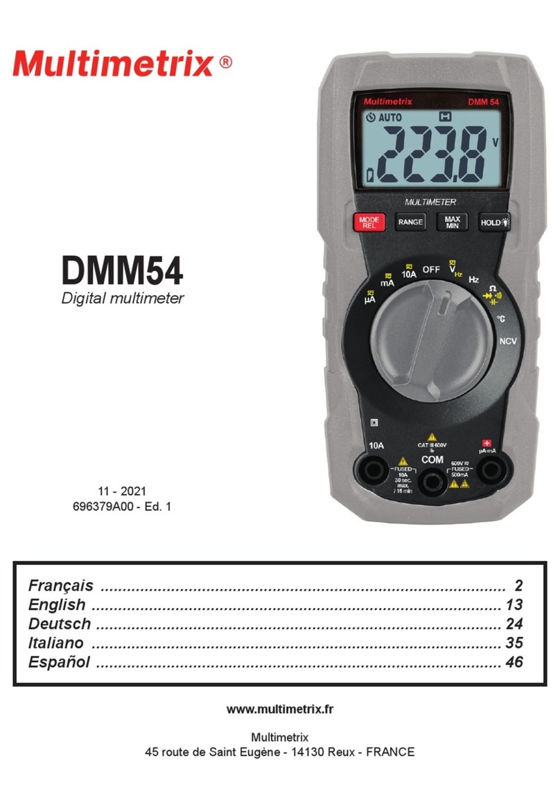
CM603
AC clamp multimeter
600V
CAT III
MAX
600A
Hz %
SLT
OFF
°C
600A
40A
COM
600V MAX
600V
CAT III
AC CLAMP METER
CM 603
AUTO RS 232
12 - 2016
695167A00 - Ed. 1
www.multimetrix.fr
Multimetrix
45 route de Saint Eugène - 14130 Reux - FRANCE

2
Vous venez d’acquérir une pince multimètre AC CM603 et nous vous
remercions de votre conance.
Pour obtenir le meilleur service de votre appareil :
lisez attentivement cette notice de fonctionnement,
respectez les précautions d’emploi.
ATTENTION, risque de DANGER ! L’opérateur doit consulter la
présente notice à chaque fois que ce symbole de danger est rencontré.
ATTENTION, risque de choc électrique. La tension appliquée sur les
pièces marquées de ce symbole peut être dangereuse.
Appareil protégé par une isolation double.
Information ou astuce utile.
Pile. Terre.
Application ou retrait autorisé sur les conducteurs sous tension
dangereuse. Capteur de courant type A selon IEC 61010-2-032.
Le produit est déclaré recyclable suite à une analyse du cycle de vie
conformément à la norme ISO14040.
Chauvin Arnoux a étudié cet appareil dans le cadre d’une démarche
globale d’éco-conception. L’analyse du cycle de vie a permis de
maîtriser et d’optimiser les effets de ce produit sur l’environnement.
Le produit répond plus précisément à des objectifs de recyclage et
de valorisation supérieurs à ceux de la réglementation.
Le marquage CE indique la conformité aux directives européennes,
notamment DBT et CEM.
La poubelle barrée signie que, dans l’Union Européenne, le produit
fait l’objet d’une collecte sélective conformément à la directive DEEE
2002/96/EC : ce matériel ne doit pas être traité comme un déchet
ménager.
FRANÇAIS
SOMMAIRE
1. PRÉSENTATION.....................................................................................3
1.1. État de livraison .......................................................................3
1.2. Mise en place des piles ............................................................3
1.3. Afcheur....................................................................................3
1.4. Présentation de l’appareil.........................................................3
2. UTILISATION ..........................................................................................4
2.1. Mesure de tension....................................................................4
2.2. Mesure de fréquence et de rapport cyclique ............................5
2.3. Mesure de courant....................................................................5
2.4. Mesure de résistance, diode et continuité................................5
2.5. Mesure de capacité ..................................................................5
2.6. Mesure de température ............................................................5
2.7. Extinction automatique .............................................................5
3. CARACTÉRISTIQUES............................................................................5
3.1. Conditions de référence ...........................................................5
3.2. Caractéristiques électriques .....................................................6
3.3. Conditions d’environnement.....................................................7
3.4. Alimentation..............................................................................7
3.5. Caractéristiques constructives..................................................7
3.6. Sécurité électrique....................................................................7
3.7. Compatibilité électromagnétique ..............................................8
4. MAINTENANCE......................................................................................8
4.1. Nettoyage .................................................................................8
4.2. Remplacement des piles ..........................................................8
5. GARANTIE .............................................................................................8

3
Dénition des catégories de mesure :
La catégorie de mesure IV correspond aux mesurages réalisés à la source
de l’installation basse tension.
La catégorie de mesure III correspond aux mesurages réalisés dans
l’installation du bâtiment.
La catégorie de mesure II correspond aux mesurages réalisés sur les circuits
directement branchés à l’installation basse tension.
PRÉCAUTIONS D’EMPLOI
Cet appareil est conforme aux normes de sécurité IEC 61010-032 et IEC 61010-
2-033, et les cordons sont conformes à l’IEC 61010-031, pour des tensions
jusqu’à 600 V en catégorie III.
Le non-respect des consignes de sécurité peut entraîner un risque de choc
électrique, de feu, d’explosion, de destruction de l’appareil et des installations.
L’opérateur et/ou l’autorité responsable doit lire attentivement et avoir une
bonne compréhension des différentes précautions d’emploi. Une bonne
connaissance et une pleine conscience des risques des dangers électriques
est indispensable pour toute utilisation de cet appareil.
Si vous utilisez cet appareil d’une façon qui n’est pas spéciée, la protection
qu’il assure peut être compromise, vous mettant par conséquent en danger.
N’utilisez pas l’appareil sur des réseaux de tensions ou de catégories
supérieures à celles mentionnées.
Respectez les conditions environnementales d’utilisation.
N’utilisez pas l’appareil s’il semble endommagé, incomplet ou mal fermé.
Avant chaque utilisation, vériez le bon état des isolants des cordons, boîtier
et accessoires. Tout élément dont l’isolant est détérioré (même partiellement)
doit être consigné pour réparation ou pour mise au rebut.
Utilisez spéciquement les cordons fournis. L’utilisation de cordons de
tension ou catégorie inférieures réduit l’utilisation de l’ensemble appareil +
cordons à la catégorie et à la tension de service les plus basses.
N’utilisez pas l’appareil dans une atmosphère explosive ou poussiéreuse.
Lors de la manipulation des pointes de touche, ne placez pas les doigts
au-delà de la garde physique.
Utilisez systématiquement des protections individuelles de sécurité.
Toute procédure de dépannage ou de vérication métrologique doit être
effectuée par du personnel compétent et agréé.
1. PRÉSENTATION
1.1. ÉTAT DE LIVRAISON
Livré sous blister avec :
trois piles 1,5 V (AAA ou LR3),
un jeu de deux cordons terminés par une pointe de touche,
un thermocouple de type K,
une che de sécurité multilingue,
une notice de fonctionnement 5 langues,
une sacoche.
1.2. MISE EN PLACE DES PILES
A l’aide d’un petit tournevis cruciforme, dévissez la vis de la trappe à pile.
Retirez la trappe à pile.
Insérer les trois piles fournies (piles 1,5 V alcaline de type AAA ou LR3).
Remettez la trappe à pile en place. Assurez-vous de sa fermeture complète
et correcte puis revissez la vis.
1.3. AFFICHEUR
Quand l’afcheur indique OL, c’est que la grandeur mesurée sort du domaine
de mesure.
1.4. PRÉSENTATION DE L’APPAREIL
La pince multimètre AC CM603 est facile d’utilisation et elle tient facilement
dans la main.
Elle peut mesurer des tensions alternatives ou continues, des courants
alternatifs, des résistances, des capacités, des fréquences, et des températures.
Elle permet aussi de déterminer des rapports cycliques, des tensions de diode
et des continuités.

4
OFF
°C
600A
40A
CM 603
Hz %
SLT
COM
600V MAX
600V
CAT III
AC CLAMP METER
AUTO RS 232
Lumière permettant d’éclairer le point
de mesure en courant.
Logement pour placer une
pointe de touche.
Touche SLT pour sélec-
tionner Ω/ / .
Touche Hz% pour afcher
la fréquence ou le rapport
cyclique.
Bornes de mesure.
Touche pour bloquer
l’affichage de la mesure
et (appui long) pour
allumer le rétroéclairage de
l’afcheur et la lumière.
Garde.
Commutateur rotatif 8
positions.
Afcheur LCD.
Gâchette.
Mâchoires de la pince.
Repères de centrage.
2. UTILISATION
2.1. MESURE DE TENSION
Connectez le cordon rouge sur la borne +et le cordon noir sur la borne COM.
Placez le commutateur sur la position Vpour mesurer une tension
continue, ou Vpour mesurer une tension alternative.
Placez les pointes de touche sur l’élément à tester, en commençant par la
pointe de touche noire, et maintenez fermement le contact.
La valeur de la tension s’afche.
À la n de la mesure,déconnectez d’abord la borne +puis la borne COM.
Avant de tourner le commutateur, retirez les pointes de touche du circuit
de test.

5
2.2. MESURE DE FRÉQUENCE ET DE RAPPORT CYCLIQUE
Connectez le cordon rouge sur la borne +et le cordon noir sur la borne COM.
Placez le commutateur sur la position Vou V.
À l’aide de la touche Hz%, choisissez la fonction désirée : Hz ou %.
Placez les pointes de touche sur l’élément à tester, et maintenez fermement
le contact.
La mesure s’afche.
2.3. MESURE DE COURANT
Placez le commutateur sur une des positions A, selon la valeur du courant
à mesurer. Si vous ne connaissez pas la valeur du courant à l’avance,
commencez par la position 600A .
Appuyez sur la gâchette pour ouvrir les mâchoires de la pince et enserrez
un seul conducteur.
Centrez le conducteur à l’intérieur des mâchoires en vous aidant des repères.
La valeur du courant s’afche.
Ne mettez pas les doigts sur les bornes pendant les mesures de
courant.
2.4. MESURE DE RÉSISTANCE, DIODE ET CONTINUITÉ
Connectez le cordon rouge sur la borne +et le cordon noir sur la borne COM.
Placez le commutateur sur la position Ω .
Coupez l’alimentation du dispositif à tester et déchargez tous les
condensateurs haute tension.
À l’aide de la touche SLT, choisissez la fonction désirée : Ω, ou .
Placez les pointes de touche sur l’élément à tester, et maintenez fermement
le contact. Pour les mesures de tension de diode, placez la pointe de touche
rouge sur la cathode et la pointe de touche noire sur l’anode.
La mesure s’afche.
Lors des mesures de faible résistance, mesurez la résistance des cordons
en court-circuitant les pointes de touches. Soustrayez cette valeur aux
mesures de faible résistance.
2.5. MESURE DE CAPACITÉ
Connectez le cordon rouge sur la borne +et le cordon noir sur la borne COM.
Placez le commutateur sur la position .
Coupez l’alimentation du dispositif à tester et déchargez tous les
condensateurs haute tension.
Placez les pointes de touche sur l’élément à tester, et maintenez fermement
le contact.
La mesure s’afche. Attendez que la mesure se stabilise.
2.6. MESURE DE TEMPÉRATURE
Connectez un thermocouple K entre les bornes +et COM.
Placez le commutateur sur la position °C.
Placez l’extrémité du thermocouple sur l’objet ou dans l’environnement
à mesurer.
La mesure s’afche. Attendez que la mesure se stabilise.
2.7. EXTINCTION AUTOMATIQUE
An d’économiser les piles, l’appareil s’éteint automatiquement au bout
de 30 minutes si l’utilisateur n’a pas manifesté sa présence en tournant le
commutateur ou en appuyant sur une touche.
Pour supprimer l’extinction automatique, appuyez sur la touche SLT en tournant
le commutateur à la mise en route.
3. CARACTÉRISTIQUES

6
3.1. CONDITIONS DE RÉFÉRENCE
Grandeur d’inuence Valeurs de référence
Température 23 ± 5 °C
Humidité relative < 80 % HR
Tension d’alimentation 4,5 ± 0,1 V
Fréquence du signal mesuré DC ou 45 à 65 Hz
Type de signal sinusoïdal
Champ électrique extérieur < 1 V/m
Champ magnétique DC extérieur < 40 A/m
Les incertitudes sont exprimées en % de la lecture (L) et en nombre de points
d’afchage (pt) : ± (a %L + b pt)
3.2. CARACTÉRISTIQUES ÉLECTRIQUES
3.3.1. TENSION
Calibre DC 4 V 40 V 400 V 600V
Résolution 1 mV 10 mV 100 mV 1 V
Incertitude
intrinsèque ± (0,8% L ± 3 pt)
Résistance
d’entrée 10 MΩ
Pour les mesures AC, la fréquence est comprise entre 40 et 400Hz, le signal
est sinusoïdal.
Calibre AC 4 V 40 V 400 V 600V
Résolution 1 mV 10 mV 100 mV 1 V
Incertitude
intrinsèque ± (1% L ± 5 pt)
Résistance
d’entrée 10 MW
3.3.2. FRÉQUENCE
Plage de mesure : 10 Hz à 10 kHz.
Protection contre les surcharges jusqu’à 600 Vac.
Tension d’entrée ≥0,2 Vac. Cette tension augmente avec la fréquence à
mesurer.
Calibre 100 Hz 1 kHz 10 kHz
Résolution 0,01 Hz 0,1 Hz 1 Hz
Incertitude intrinsèque ± (1% L ± 5 pt)
3.3.3. RAPPORT CYCLIQUE
Étendue de mesure 0,1 - 99,9 %
Résolution 0,1 %
Incertitude intrinsèque ± 2%
3.3.4. COURANT
La fréquence est comprise entre 50 et 60Hz, le signal est sinusoïdal.
Courant maximal : 120% du calibre pendant moins de 60 secondes.
Calibre AC 40 A 400 A 600 A
Résolution 10 mA 100 mA 1 A
Incertitude
intrinsèque ± (2,5% L ± 5 pt)

7
3.3.5. RÉSISTANCE
Tension en circuit ouvert : 0,4 Vdc environ.
Calibre Résolution Incertitude intrinsèque
400 W0,1 W
± (1% L ± 5 pt)
4 kW1 W
40 kW10 W
400 kW100 W
4 MW1 kW
40 MW10 kW± (2% L ± 5 pt)
3.3.6. TEST DIODE
Courant direct : 1 mAdc environ.
Tension inverse : 3 Vdc environ.
Fonction Résolution Afchage
1 mV L'afcheur indique la tension inverse de diode.
3.3.7. CONTINUITÉ
Tension en circuit ouvert : 1 Vdc environ.
L’appareil émet un signal sonore lorsque la mesure est < 40 Ω environ.
3.3.8. CAPACITÉ
Calibre 10 nF 100 nF 1 µF 10 µF 100 µF 1 mF 10 mF
Résolution 1 pF 10 pF 100 pF 1 nF 10 nF 100 nF 1 µF
Incertitude
intrinsèque
± (4% L ±
5 pt) ± (3% L ± 3 pt)
3.3.9. TEMPÉRATURE
Étendue de mesure -20 °C ... +1000 °C
Résolution 1 °C
Incertitude intrinsèque ± (3% L ± 3 pt)
3.3. CONDITIONS D’ENVIRONNEMENT
Domaine de fonctionnement : 0 à 40°C et <80%HR hors condensation.
Domaine de stockage (sans piles) : -10 à +60°C et <70%HR hors condensation.
En cas de non utilisation prolongée ou de stockage, retirez les piles du boîtier.
Utilisation en intérieur et en extérieur sans pluie.
Degré de pollution : 2.
Altitude : < 2000 m.
3.4. ALIMENTATION
L’alimentation est réalisée par trois piles 1,5 V alcaline (type AAA ou LR3).
3.5. CARACTÉRISTIQUES CONSTRUCTIVES
Dimensions (L x l x P) 206 x 79 x 43 mm
Diamètre d’enserrage 26 mm
Masse environ 270 g
Chute 2 m.
3.6. SÉCURITÉ ÉLECTRIQUE
Sécurité électrique 600 V CAT III selon l’IEC 61010-1, l’IEC 61010-032 et
l’IEC 61010-033.
Conforms to UL Std. 61010-1, 61010-2-030, 61010-2-033
Certied to CSA Std. C22.2 No. 61010-1, 61010-2-030, IEC std.
61010-2-033.

8
3.7. COMPATIBILITÉ ÉLECTROMAGNÉTIQUE
Émission et immunité en milieu industriel selon IEC 61326-1.
4. MAINTENANCE
Excepté les piles, l’appareil ne comporte aucune pièce susceptible d’être
remplacée par un personnel non formé et non agréé. Toute intervention
non agréée ou tout remplacement de pièce par des équivalences risque
de compromettre gravement la sécurité.
4.1. NETTOYAGE
Déconnectez tout branchement de l’appareil et placez le commutateur sur OFF.
Utilisez un chiffon doux, légèrement imbibé d’eau savonneuse. Rincez avec
un chiffon humide et séchez rapidement avec un chiffon sec ou de l’air pulsé.
N’utilisez pas d’alcool, de solvant ou d’hydrocarbure.
Maintenez les entrefers de la pince en parfait état de propreté.
4.2. REMPLACEMENT DES PILES
Si le symbole s’afche, vous devez remplacer les piles.
Déconnectez tout branchement de l’appareil et placez le commutateur
sur OFF.
Reportez-vous au § 1.2 pour démonter la trappe à pile.
Remplacez toutes les piles usagées par des piles neuves de type AAA
ou LR03.
Les piles et les accumulateurs usagés ne doivent pas être traités comme
des déchets ménagers. Rapportez-les au point de collecte approprié pour
le recyclage.
5. GARANTIE
Notre garantie s’exerce, sauf stipulation expresse, pendant douze mois après
la date de mise à disposition du matériel. L’extrait de nos Conditions Générales
de Vente sera communiqué sur demande.
La garantie ne s’applique pas suite à :
une utilisation inappropriée de l’équipement ou à une utilisation avec un
matériel incompatible ;
des modications apportées à l’équipement sans l’autorisation explicite du
service technique du fabricant ;
des travaux effectués sur l’appareil par une personne non agréée par le
fabricant ;
une adaptation à une application particulière, non prévue par la dénition du
matériel ou non indiquée dans la notice de fonctionnement ;
des dommages dus à des chocs, chutes ou inondations.

9
Thank you for purchasing this AC CM603 clamp multimeter.
For best results from your instrument:
read these operating instructions carefully,
comply with the precautions for use.
WARNING, risk of DANGER! The operator must refer to these
instructions whenever this danger symbol appears.
WARNING, risk of electric shock. The voltage applied to parts marked
with this symbol may be hazardous.
Equipment protected by double insulation.
Information or useful tip.
Battery. Earth.
Can be applied to or removed from conductors at dangerous voltages.
Type A current sensor per IEC 61010-2-032.
The product is declared recyclable following an analysis of the life
cycle in accordance with standard ISO 14040.
Chauvin Arnoux has adopted an Eco-Design approach in order
to design this appliance. Analysis of the complete lifecycle has
enabled us to control and optimize the effects of the product on
the environment. In particular this appliance exceeds regulation
requirements with respect to recycling and reuse.
The CE marking indicates conformity with European directives, in
particular LVD and EMC.
The rubbish bin with a line through it indicates that, in the European
Union, the product must undergo selective disposal in compliance
with Directive WEEE 2002/96/EC. This equipment must not be treated
as household waste.
ENGLISH
CONTENTS
1. PRESENTATION...................................................................................10
1.1. Delivery condition ...................................................................10
1.2. Inserting the batteries.............................................................10
1.3. Display unit.............................................................................10
1.4. Presentation of the instrument................................................10
2. USE .......................................................................................................11
2.1. Voltage measurement.............................................................11
2.2. Frequency and duty cycle measurements..............................12
2.3. Current measurement.............................................................12
2.4. Resistance, diode, and continuity measurements..................12
2.5. Capacitance measurement.....................................................12
2.6. Temperature measurement.....................................................12
2.7. AUTO OFF..............................................................................12
3. CHARACTERISTICS ............................................................................12
3.1. Reference conditions..............................................................12
3.2. Electrical characteristics.........................................................13
3.3. Environmental conditions .......................................................14
3.4. Power supply..........................................................................14
3.5. Characteristics of construction ...............................................14
3.6. Electrical safety ......................................................................14
3.7. Electromagnetic compatibility.................................................14
4. MAINTENANCE....................................................................................15
4.1. Cleaning .................................................................................15
4.2. Replacement of batteries........................................................15
5. WARRANTY..........................................................................................15

10
Denition of measurement categories:
Measurement category IV corresponds to measurements taken at the source
of low-voltage installations.
Measurement category III corresponds to measurements on building
installations.
Measurement category II corresponds to measurements taken on circuits
directly connected to low-voltage installations.
PRECAUTIONS FOR USE
This instrument is compliant with safety standards IEC61010-032 and
IEC61010-2-033, and the leads are compliant with IEC61010-031, for voltages
up to 600V in category III.
Failure to observe the safety instructions may result in electric shock, re,
explosion, and destruction of the instrument and of the installations.
The operator and/or the responsible authority must carefully read and
clearly understand the various precautions to be taken in use. Sound
knowledge and a keen awareness of electrical hazards are essential when
using this instrument.
If you use this instrument other than as specied, the protection it provides
may be compromised, thereby endangering you.
Do not use your instrument on networks of which the voltage or category
exceeds those stated.
Observe the environmental conditions of use.
Do not use the instrument if it seems to be damaged, incomplete, or
poorly closed.
Before each use, check the condition of the insulation on the leads, housing,
and accessories. Any item of which the insulation is deteriorated (even
partially) must be set aside for repair or scrapping.
Use only the leads supplied. The use of leads of a lower voltage rating or
category limits the use of the combined instrument + leads to the lowest
category and service voltage.
Do not use the instrument in an explosive or dust-laden atmosphere.
When handling the test probes, keep your ngers behind the physical guard.
Use personal protection equipment systematically.
All troubleshooting and metrological checks must be done by competent,
accredited personnel.
1. PRESENTATION
1.1. DELIVERY CONDITION
Delivered in blister pack with:
three 1.5V batteries (AAA or LR3),
one set of two leads each terminated by a probe tip,
one type K thermocouple,
one multilingual safety data sheet,
one user’s manual in ve languages,
one carrying case.
1.2. INSERTING THE BATTERIES
Using a small cross-headed screwdriver, unscrew the screws of the battery
compartment cover.
Withdraw the battery compartment cover.
Insert the three batteries provided (AAA or LR3 1.5V alkaline batteries).
Put the battery compartment cover back in place. Make sure that it is
completely and correctly closed, then screw the screws back in.
1.3. DISPLAY UNIT
When the display unit indicates OL, it is because the quantity measured lies
outside the measurement range.
1.4. PRESENTATION OF THE INSTRUMENT
The hand-held AC CM603 clamp multimeter is easy to use.
It can be used to measure AC or DC voltages, AC currents, resistances,
capacitances, frequencies, and temperatures. It can also be used to determine
duty cycles, diode voltages, and continuities.

11
OFF
°C
600A
40A
CM 603
Hz %
SLT
COM
600V MAX
600V
CAT III
AC CLAMP METER
AUTO RS 232
Light used to illuminate the current
measurement point.
Space for a probe tip.
SLT key to select Ω/ / .
Hz% key to display the
frequency or the duty cycle.
Measurement terminals.
key to lock the display of
the measurement and
(long press) to switch on the
display unit backlight and
the ashlight.
Guards.
Eight-position rotary switch.
LCD display unit.
Trigger.
Jaws of the clamp.
Centering marks.
2. USE
2.1. VOLTAGE MEASUREMENT
Connect the red lead to the + terminal and the black lead to the COM terminal.
Set the switch to Vto measure a DC voltage, or Vto measure an AC
voltage.
Place the probe tips on the element to be tested, starting with the black
probe tip, and maintain rm contact.
The voltage is displayed.
At the end of the measurement, disconnect the + terminal rst, then the
COM terminal.
Before turning the switch, withdraw the probe tips from the circuit being
tested.

12
2.2. FREQUENCY AND DUTY CYCLE MEASUREMENTS
Connect the red lead to the + terminal and the black lead to the COM terminal.
Set the switch to V or V.
Use the Hz% key to select the desired function: Hz or %.
Place the test probes on the element to be tested and maintain a rm contact.
The measurement is displayed.
2.3. CURRENT MEASUREMENT
Set the switch to one of the Apositions, depending on the value of the current
to be measured. If you do not know the value of the current in advance,
start in the 600A setting.
Press the trigger to open the jaws of the clamp and clamp only one conductor.
Center the conductor in the jaws with the help of the marks.
The current is displayed.
Keep your ngers away from the terminals during current measurements.
2.4. RESISTANCE, DIODE, AND CONTINUITY MEASUREMENTS
Connect the red lead to the + terminal and the black lead to the COM terminal.
Set the switch to Ω .
Cut off power to the device to be tested and discharge all high-voltage
capacitors.
Use the SLT key to select the desired function: Ω, or .
Place the test probes on the element to be tested and maintain a rm contact.
For diode voltage measurements, place the red probe tip on the cathode
and the black probe tip on the anode.
The measurement is displayed.
For low resistance measurements, measure the resistance of the leads
by short-circuiting the probe tips. Subtract the value so found from the
low resistance measurements.
2.5. CAPACITANCE MEASUREMENT
Connect the red lead to the + terminal and the black lead to the COM terminal.
Set the switch to .
Cut off power to the device to be tested and discharge all high-voltage
capacitors.
Place the test probes on the element to be tested and maintain a rm contact.
The measurement is displayed. Wait for the measurement to stabilize.
2.6. TEMPERATURE MEASUREMENT
Connect a K thermocouple between the +and COM terminals.
Set the switch to °C.
Place the end of the thermocouple on the object or in the environment to
be measured.
The measurement is displayed. Wait for the measurement to stabilize.
2.7. AUTO OFF
To save the batteries, the instrument switches itself off automatically after 30
minutes if the user has not shown signs of being present by turning the switch
or pressing a key.
To suppress auto off, press the SLT key while turning the switch when starting
up.
3. CHARACTERISTICS
3.1. REFERENCE CONDITIONS
Quantity of inuence Reference values
Temperature 23 ±5°C
Relative humidity <80% RH
Supply voltage 4.5 ±0.1V
Frequency of the measured signal DC or 45 to 65Hz
Type of signal sinusoidal
External electric eld <1V/m
DC external magnetic eld <40A/m

13
The uncertainties are expressed in % of the reading (R) and in number of
display points (pt): ±(a% R + b pt)
3.2. ELECTRICAL CHARACTERISTICS
3.3.1. VOLTAGE
DC range 4V 40V 400V 600V
Resolution 1mV 10mV 100mV 1V
Intrinsic
uncertainty ±(0.8% R ±3 pt)
Input
resistance 10MΩ
For AC measurements, the frequency is between 40 and 400Hz and the signal
is sinusoidal.
AC range 4V 40V 400V 600V
Resolution 1mV 10mV 100mV 1V
Intrinsic
uncertainty ±(1% R ±5 pt)
Input
resistance 10MW
3.3.2. FREQUENCY
Measurement range: 10Hz to 10kHz.
Overload protection up to 600 Vac.
Input voltage ≥2 Vac. This voltage increases with the frequency to be measured.
Range 100 Hz 1 kHz 10 kHz
Resolution 0,01 Hz 0,1 Hz 1 Hz
Intrinsic uncertainty ± (1% R ± 5 pt)
3.3.3. DUTY CYCLE
Measurement range 0.1-99.9%
Resolution 0.1%
Intrinsic uncertainty ±2%
3.3.4. CURRENT
The frequency is between 50 and 60Hz and the signal is sinusoidal.
Maximum current: 120% of the range for less than 60 seconds.
AC range 40A 400A 600A
Resolution 10mA 100mA 1A
Intrinsic
uncertainty ±(2.5% R ±5 pt)
3.3.5. RESISTANCE
Open-circuit voltage: approximately 0.4 Vdc.
Range Resolution Intrinsic uncertainty
400W0,1W
±(1% R ±5 pt)
4kW1W
40kW10W
400kW100W
4MW1kW
40MW10kW±(2% R ±5 pt)

14
Conforms to UL Std. 61010-1, 61010-2-030, 61010-2-033
Certied to CSA Std. C22.2 No. 61010-1, 61010-2-030, IEC std.
61010-2-033.
3.3.6. DIODE TEST
Forward current: 1mAdc environ.
Reverse voltage: 3 Vdc environ.
Function Resolution Display
1mV The display unit indicates the reverse voltage
of the diode.
3.3.7. CONTINUITY
Open-circuit voltage: 1 Vdc environ.
The instrument emits an audible signal when the measurement is below
approximately 40Ω.
3.3.8. CAPACITY
Range 10 nF 100 nF 1 µF 10 µF 100 µF 1 mF 10 mF
Resolution 1 pF 10 pF 100 pF 1 nF 10 nF 100 nF 1 µF
Intrinsic
uncertainty
± (4% R ±
5 pt) ± (3% R ±3 pt)
3.3.9. TEMPERATURE
Measurement range -20°C ... +1000°C
Resolution 1°C
Intrinsic uncertainty ±(3% R ±3 pt)
3.3. ENVIRONMENTAL CONDITIONS
Operating range: 0 to 40°C and <80%RH without condensation.
Storage range (without batteries): -10 to +60°C and <70%RH without
condensation.
If an extended period of non-use is anticipated, or for storage, withdraw the
batteries from the housing.
For use indoors and outdoors without rain.
Pollution degree: 2.
Altitude: <2000m.
3.4. POWER SUPPLY
The instrument is powered by three 1.5V alkaline batteries (type AAA or LR3).
3.5. CHARACTERISTICS OF CONSTRUCTION
Dimensions (L x l x P) 206 x 79 x 43mm
Clamping diameter 26mm
Mass 270g approx.
Drop test 2m.
3.6. ELECTRICAL SAFETY
Electrical safety 600V CAT III per IEC 61010-1, IEC 61010-032 and IEC
61010-033.
3.7. ELECTROMAGNETIC COMPATIBILITY
Emission and immunity in industrial environment according to IEC 61326-1.

15
4. MAINTENANCE
Except for the batteries, the instrument contains no parts that can be
replaced by personnel who have not been specially trained and accredited.
Any unauthorized repair or replacement of a part by an “equivalent” may
gravely impair safety.
4.1. CLEANING
Disconnect everything connected to the instrument and set the switch to OFF.
Use a soft cloth, dampened with soapy water. Rinse with a damp cloth and
dry rapidly with a dry cloth or forced air. Do not use alcohol, solvents, or
hydrocarbons.
Keep the air gaps of the clamp perfectly clean.
4.2. REPLACEMENT OF BATTERIES
If the symbol is displayed during a measurement, you must replace the
batteries.
Disconnect everything connected to the instrument and set the switch to OFF.
Refer to §1.2 to remove the battery compartment cover.
Replace all spent batteries with new AAA or LR03 batteries.
Spent batteries must not be treated as ordinary household waste. Take
them to the appropriate recycling collection point.
5. WARRANTY
Except as otherwise stated, our warranty is valid for twelve months starting
from the date on which the equipment was sold. Extract from our General
Conditions of Sale provided on request.
The warranty does not apply in the following cases:
Inappropriate use of the equipment or use with incompatible equipment;
Modications made to the equipment without the explicit permission of the
manufacturer’s technical staff;
Work done on the device by a person not approved by the manufacturer;
Adaptation to a particular application not anticipated in the denition of the
equipment or not indicated in the user’s manual;
Damage caused by shocks, falls, or oods.

16
Sie haben eine AC-Vielfachmesszange CM603 erworben, wir danken Ihnen
für das damit entgegengebrachte Vertrauen.
Um die optimale Benutzung Ihres Gerätes zu gewährleisten, bitten wir Sie:
diese Bedienungsanleitung sorgfältig zu lesen,
die Benutzungshinweise genau zu beachten.
ACHTUNG, GEFAHR! Sobald dieses Gefahrenzeichen irgendwo
erscheint, ist der Benutzer verpichtet, die Anleitung zu Rate zu ziehen.
ACHTUNG! Gefahr eines elektrischen Stromschlags. Mit diesem
Symbol gekennzeichnete Teile stehen möglicherweise unter
Gefahrenspannung!
Das Gerät ist durch eine doppelte Isolierung geschützt.
Praktischer Hinweis oder guter Tipp.
Batterie Erde.
Darf auf nicht isolierten Leitern unter gefährlicher Spannung
angewendet werden. Stromsonde Typ A gemäß IEC 61010-2-032.
Die Lebenszyklusanalyse des Produkts gemäß ISO14040 hat
ergeben, dass das Produkt als recyclingfähig eingestuft wird.
Chauvin Arnoux hat dieses Gerät im Rahmen eines umfassenden
Projektes einer umweltgerechten Gestaltung untersucht. Die
Lebenszyklusanalyse hat die Kontrolle und Optimierung der
Auswirkungen dieses Produkts auf die Umwelt ermöglicht. Genauer
gesagt, entspricht dieses Produkt den gesetzten Zielen hinsichtlich
Wiederverwertung und Wiederverwendung besser als dies durch die
gesetzlichen Bestimmungen festgelegt ist.
Die CE-Kennzeichnung bestätigt die Übereinstimmung mit den
europäischen Richtlinien, insbesondere der Niederspannungs-
Richtlinie und der EMV-Richtlinie.
Der durchgestrichene Mülleimer bedeutet, dass das Produkt in der
europäischen Union gemäß der WEEE-Richtlinie 2002/96/EG einer
getrennten Elektroschrott-Verwertung zugeführt werden muss. Das
Produkt darf nicht als Haushaltsmüll entsorgt werden.
DEUTSCH
INHALTSVERZEICHNIS
1. VORSTELLUNG ...................................................................................17
1.1. Lieferumfang ..........................................................................17
1.2. Batterien einlegen...................................................................17
1.3. Anzeige...................................................................................17
1.4. Gerätevorstellung ...................................................................17
2. VERWENDUNG ....................................................................................18
2.1. Spannungsmessungen...........................................................18
2.2. Frequenzmessung und Tastverhältnis....................................19
2.3. Strommessung .......................................................................19
2.4. Widerstand-, Dioden- und Durchgangsprüfung......................19
2.5. Kapazitätsmessungen ............................................................19
2.6. Temperaturmessung...............................................................19
2.7. Automatische Ausschaltung....................................................19
3. TECHNISCHE DATEN ..........................................................................19
3.1. Referenzbedingungen ............................................................20
3.2. Elektrische Daten ...................................................................20
3.3. Umgebungsbedingungen .......................................................21
3.4. Stromversorgung....................................................................21
3.5. Allgemeine Baudaten..............................................................21
3.6. Elektrische Sicherheit.............................................................21
3.7. Elektromagnetische Verträglichkeit ........................................22
4. WARTUNG............................................................................................22
4.1. Reinigung ...............................................................................22
4.2. Batterien wechseln .................................................................22
5. GARANTIE ...........................................................................................22

17
Denition der Messkategorien:
Die Kategorie IV bezieht sich auf Messungen, die an der Quelle von
Niederspannungsinstallationen vorgenommen werden.
Die Kategorie III bezieht sich auf Messungen, die an der Elektroinstallation
eines Gebäudes vorgenommen werden.
Die Kategorie II bezieht sich auf Messungen, die direkt an Kreisen der
Niederspannungsinstallation vorgenommen werden.
SICHERHEITSHINWEISE
Dieses Gerät entspricht den Sicherheitsnormen IEC61010-032 und IEC61010-
2-033, die Messleitungen IEC61010-031 für Spannungen bis 600V in
Messkategorie III.
Die Nichtbeachtung der Sicherheitshinweise kann zu Gefahren durch
elektrische Schläge, durch Brand oder Explosion, sowie zur Zerstörung des
Geräts und der Anlage führen.
Der Benutzer bzw. die verantwortliche Stelle müssen die verschiedenen
Sicherheitshinweise sorgfältig lesen und gründlich verstehen. Die
umfassende Kenntnis und das Bewusstsein der elektrischen Gefahren sind
bei jeder Benutzung dieses Gerätes unverzichtbar.
Wenn das Gerät in unsachgemäßer und nicht spezizierter Weise benutzt
wird, kann der eingebaute Schutz nicht mehr gewährleistet sein und eine
Gefahr für den Benutzer entstehen.
Verwenden Sie das Gerät niemals an Netzen mit höheren Spannungen
oder Messkategorien als den angegebenen.
Achten Sie auf die Umweltdaten für den Gerätebetrieb.
Verwenden Sie das Gerät niemals, wenn es beschädigt, unvollständig oder
schlecht geschlossen erscheint.
Prüfen Sie vor jedem Einsatz nach, ob die Isolierung der Drähte, des
Gehäuses und des Zubehörs einwandfrei ist. Teile mit auch nur stellenweise
beschädigter Isolierung müssen für eine Reparatur oder für die Entsorgung
ausgesondert werden.
Verwenden Sie ausschließlich die mitgelieferten Messleitungen. Wenn
Messleitungen niedrigerer Kategorie bzw. geringerer Spannung verwendet
wird, gilt für das ganze Messmodul (Gerät+Leitungen) die jeweils niedrigste
Kategorie und Betriebsspannung.
Dieses Gerät darf nicht in explosibler Atmosphäre und staubiger Umgebung
verwendet werden
Fassen Sie Prüfspitzen immer nur hinter dem Fingerschutz an.
Verwenden Sie stets die eine persönliche Schutzausrüstung.
Fehlerbehebung und Eichung darf nur durch zugelassenes Fachpersonal
erfolgen.
1. VORSTELLUNG
1.1. LIEFERUMFANG
Lieferung in Blisterverpackung mit
3 Alkalibatterien 1,5V (AAA bzw. LR6)
1 Satz Leitungen mit Prüfspitze
1 K-Thermoelement
1 mehrsprachiges Sicherheitsdatenblatt
1 Bedienungsanleitung in 5 Sprachen
1 Tasche
1.2. BATTERIEN EINLEGEN
Die Schrauben des Batteriefachs mit einem kleinen Kreuzschraubendreher
komplett lösen.
Batteriefachdeckel entfernen.
Die drei mitgelieferten Batterien (1,5VAlkalibatterien,AAAbzw. LR3) einlegen.
Bringen Sie den Batteriefachdeckel wieder an. Stellen Sie sicher, dass
der Batteriefachdeckel ganz und richtig geschlossen ist und schrauben
Sie ihn ganz zu.
1.3. ANZEIGE
Wenn der gemessene Wert den Messbereich überschreitet, zeigt das Gerät OL an.
1.4. GERÄTEVORSTELLUNG
CM603 ist eine bedienerfreundliche, tragbare AC-Vielfachmesszange.
Sie misst AC- und DC-Spannungen, AC-Ströme, sowie Widerstände,
Kapazitäten, Frequenzen und Temperaturen. Außerdem lassen sich damit
Tastverhältnis, Diodenspannung und Durchgang bestimmen.

18
OFF
°C
600A
40A
CM 603
Hz %
SLT
COM
600V MAX
600V
CAT III
AC CLAMP METER
AUTO RS 232
Mit Lampe zum Beleuchten des
Strommesspunkts.
Platz für eine Prüfspitze.
Taste SLT zur Auswahl von
Ω/ / .
Taste Hz% zur Anzeige
von Frequenz bzw.
Tastverhältnis.
Messeingänge.
Taste zum „Einfrieren“
der Messanzeige, sowie
bei langem Drücken
zum Einschalten der
Anzeigenbeleuchtung und
der Lampe.
Fingerschutz.
Drehschalter mit 8
Stellungen.
LCD-Anzeige
Trigger.
Zangenbacken.
Zentriermarken.
2. VERWENDUNG
2.1. SPANNUNGSMESSUNGEN
Stecken Sie den roten Prüfdraht in die +-Buchse und den Schwarzen in
die COM-Buchse.
Stellen Sie den Schalter auf die Position Vzum Messen einer
Gleichspannung, auf Vzum Messen einer Wechselspannung.
Halten Sie die Prüfspitzen fest an den Prüing, beginnen Sie dabei mit der
schwarzen Spitze.
Der Spannungswert wird angezeigt.
Nach dem Messen lösen Sie zuerst die +-Buchse und dann die COM-
Buchse.
Nehmen Sie die Prüfspitzen vom geprüften Schaltkreis, bevor Sie den
Drehschalter betätigen.

19
2.2. FREQUENZMESSUNG UND TASTVERHÄLTNIS
Stecken Sie den roten Prüfdraht in die +-Buchse und den Schwarzen in
die COM-Buchse.
Stellen Sie den Drehschalter auf Stellung V oder V .
Wählen Sie nun mit der Taste Hz% die gewünschte Funktion: Hz oder %.
Halten Sie die Prüfspitzen fest an den Prüing.
Der Messwert wird angezeigt.
2.3. STROMMESSUNG
Stellen Sie je nach gemessenem Stromwert den Drehschalter auf eine der
AStellungen. Sollten Sie den Stromwert nicht im Voraus kennen, beginnen
Sie zuerst mit der Stellung 600A .
Öffnen Sie die Backen mithilfe des Triggers. Achtung, die Zange darf nur
jeweils an einen Leiter geklemmt werden.
Das Kabel sollte möglichst mittig zwischen den Zangenbacken liegen, achten
Sie beim Zentrieren auf die Markierungen.
Der Stromwert wird angezeigt.
Greifen Sie beim Strommessen die Buchsen nicht an.
2.4. WIDERSTAND-, DIODEN- UND DURCHGANGSPRÜFUNG
Stecken Sie den roten Prüfdraht in die +-Buchse und den Schwarzen in
die COM-Buchse.
Stellen Sie den Schalter auf die Position Ω .
Zuerst müssen die Stromzufuhr des Prüflings unterbrochen und alle
Hochspannungskapazitäten entladen werden.
Wählen Sie nun mit der Taste SLT die gewünschte Funktion: Ω, oder .
Halten Sie die Prüfspitzen fest an den Prüfling. Beim Messen der
Diodenspannung halten Sie die rote Prüfspitze an die Kathode und die
schwarze Prüfspitze an die Anode.
Der Messwert wird angezeigt.
Beim Messen kleiner Widerstände werden zum Messen des
Messleitungswiderstands die Prüfspitzen kurzgeschlossen. Subtrahieren
Sie diesen Wert von den Messwerten kleiner Widerstände.
2.5. KAPAZITÄTSMESSUNGEN
Stecken Sie den roten Prüfdraht in die +-Buchse und den Schwarzen in
die COM-Buchse.
Stellen Sie den Schalter auf die Position .
Zuerst müssen die Stromzufuhr des Prüflings unterbrochen und alle
Hochspannungskapazitäten entladen werden.
Halten Sie die Prüfspitzen fest an den Prüing.
Der Messwert wird angezeigt. Warten, bis sich der Messwert stabilisiert hat.
2.6. TEMPERATURMESSUNG
Schließen Sie ein K-Thermoelement an die Buchsen +und COM an.
Stellen Sie den Drehschalter auf Stellung °C.
Halten Sie das Thermoelement an den Prüing bzw. in die Umgebung, die
gemessen werden soll.
Der Messwert wird angezeigt. Warten, bis sich der Messwert stabilisiert hat.
2.7. AUTOMATISCHE AUSSCHALTUNG
Wenn der Benutzer den Drehschalter bzw. die Tasten nicht betätigt, schaltet
sich das Gerät nach 30 Minuten automatisch ab, um die Batterien zu schonen.
Um die Abschaltautomatik aufzuheben, drücken Sie beim Einschalten mit dem
Schalter gleichzeitig die SLT-Taste.
3. TECHNISCHE DATEN

20
3.1. REFERENZBEDINGUNGEN
Einussgröße Bezugswerte
Temperatur 23 ±5°C
Relative Luftfeuchte <80% r.F.
Versorgungsspannung 4,5 ± 0,1V
Signalfrequenz des Messsignals DC oder 45 … 65Hz
Signalform Sinus
Elektrische Feldstärke < 1V/m
Magnetfeldstärke DC < 40A/m
Die Unsicherheiten werden in % des Leswerts und Anzeigedatenpunkten (D)
ausgedrückt: ± (a %L + b D)
3.2. ELEKTRISCHE DATEN
3.3.1. SPANNUNG
DC-Bereich 4V 40V 400V 600V
Auösung 1mV 10mV 100mV 1V
Eigenun-
sicherheit ±(0,8% L ±3 D)
Eingangs-
widerstand 10MΩ
Bei AC-Messungen liegt die Frequenz zwischen 40 und 400Hz, das Signal
ist sinusförmig.
AC-Bereich 4V 40V 400V 600V
Auösung 1mV 10mV 100mV 1V
Eigenun-
sicherheit ±(1% L ±5 D)
Eingangs-
widerstand 10MW
3.3.2. FREQUENZ
Messbereich: 10Hz bis 10kHz
Überlastschutz bis 600 Vac.
Eingangsspannung ≥0,2 Vac. Diese Spannung nimmt mit der gemessenen
Frequenz zu.
Messbereich 100 Hz 1 kHz 10 kHz
Auösung 0,01 Hz 0,1 Hz 1 Hz
Eigenunsicherheit ± (1% L ±5 D)
3.3.3. TASTVERHÄLTNIS
Messspanne 0,1-99,9%
Auösung 0,1%
Eigenunsicherheit ±2%
3.3.4. STROM
Die Frequenz liegt zwischen 50 und 60Hz, das Signal ist sinusförmig.
Max. Strom: 120 % des Messbereichs für höchstens 60 Sekunden.
AC-Bereich 40A 400A 600A
Auösung 10mA 100mA 1A
Eigenun-
sicherheit ±(2,5% L ±5 D)
Table of contents
Languages:
Other Multimetrix Multimeter manuals

Multimetrix
Multimetrix DMM 240 User manual

Multimetrix
Multimetrix DMM 13 User manual

Multimetrix
Multimetrix DMM 107 User manual

Multimetrix
Multimetrix DMM 230 User manual

Multimetrix
Multimetrix DMM54 User manual

Multimetrix
Multimetrix DMM 210 User manual

Multimetrix
Multimetrix CM 605 User manual

Multimetrix
Multimetrix DMM111 User manual

Multimetrix
Multimetrix DMM 220 User manual

Multimetrix
Multimetrix DMM121 User manual