Elikliv DM9 User manual

1
Elikliv model DM9 Digital Microscope
Enhanced User’s Manual
Overview
The DM9 is a ‘monocular’ microscope that uses a solid-state sensor element to capture an
image(s) of the subject, and a back-illuminated LCD display screen to allow viewing of the
captured image(s). A microcontroller inside the LCD display handles image processing and
display. In addition to capturing still images, the microscope also allows capturing video.
Because the microscope is ‘monocular’, it can only manage 2-dimensional images, and cannot
depict the third ‘height’ dimension, thus the user cannot perceive or judge depth in the displayed
image.
The captured still images are stored as JPEG (JPG) files, and captured videos are stored as AVI
files, with both types of files being saved to a microSD memory card (SD for short) that plugs
into the side of the LCD display (“LCD” for short). The microscope does NOT save images and
videos to the SD card if the LCD is plugged into a PC (personal computer) via a USB cable; in
that case, the photo/video capture software on the PC will handle recording of images and videos
to files, and the file types will depend on the application software used.
The microscope has an integral annular set of LEDs encircling the lens to provide illumination of
the subject; a control wheel on the LCD allows adjustment of the brightness from this light
source. The base of the microscope also has two auxiliary “gooseneck” LED lamps (henceforth
referred to as “auxiliary lamps”); these have their own dedicated brightness control wheel on the
rear of the base. Note that both brightness control wheels are poorly scaled, thus most of the
adjust occurs near one end of the control wheel rotation, the rest of the rotation being a ‘dead
zone’.
Basic Microscope Operation
Review the rest of this manual for details.
Turn on the LCD using the Power button. Turn the annual LED lamp in the microscope on or off
as required, and adjust the brightness as desired; do similarly with the Auxiliary LED lamps on
the Base. Place the ‘subject’ (the object that you will be looking at) on the Base, with the area of
interest positioned directly below the lens in the bottom end of the microscope. Adjust the Focus
Wheel near the bottom end of the microscope until the area of interest is in clear focus. To
change the magnification, raise or lower the microscope on its stand by use of the two black
knurled knobs that are on either side of the Holder by the Stand; it will be necessary to re-focus
every time the magnification is changed. Minimum magnification is obtained with the
microscope fully raised, maximum magnification requires the microscope to be fully lowered.

2
Table of Contents
Overview 1
Basic Microscope Operation 1
Table of Contents 2
Power Source 3
Memory 3
Power & Battery Charging 4
Parts of the Microscope 5
Menu 7
Selecting the Mode 12
To Take a Still Photo 13
To Take a Video 13
Playback 13
Ports 15
Connecting to a PC 17
Specifications 18
A Note on the Magnification 18

3
Power Source
The microscope and the LCD get their power from an integral, replaceable, type 18650 lithium-
ion battery, which is located behind a sliding cover on the rear of the LCD. The 18650 produces
3.7V with a capacity of about 3000mAh. Circuitry integral to the LCD boosts the battery voltage
as required, and also handles charge management of the battery. There is reason to expect that
the LCD will not charge the battery very much, if at all, while the microscope is turned on; for
best/fastest charging, the microscope should be turned off. Charging a mostly depleted battery
should take between 1 and 2 hours, assuming that a USB power adapter/charger of at least 2A
capacity is used (it is not included with the microscope and must be obtained separately). The
battery can also be charged by connecting the LCD to a personal computer (PC) via a suitable
USB cable. The cable must have a micro-USB plug on the end that will connect to the LCD.
The auxiliary gooseneck LED lamps are powered via another micro-USB socket, located on the
rear of the microscope’s Base. A PC or a USB power adapter/charger may be used as the power
source for the Base’s auxiliary lamps. Alternately, the same cable that is used to connect the
wired remote control to the LCD has a branch cable that can reach the micro-USB socket on the
Base, so that the LCD’s battery (or USB power source) also supplies power to the lamps on the
Base.
Memory
The microscope can store still images (as JPG files) and video (as AVI files) locally on a
microSD memory card that is plugged into the LCD. Any images or video saved to the SD card
can be read back and viewed on the LCD. Purportedly, any connected PC might be unable to
read the contents of the SD card while it remains plugged into the LCD, although the SD card
may be unplugged from the LCD and inserted into an SD card reader on a PC for purposes of
reading the card’s files in that manner. If the LCD is connected via USB to a PC, the
microscope’s camera can be read directly and continuously as a generic ‘PC camera’ and
whatever it sees can be viewed, manipulated, and stored on the PC.
When the LCD is connected to a PC, all pushbutton controls on the LCD and the wired remote
control are disabled, so the only access to the microscope’s camera is by way of the PC and its
software.
Because most PC’s do not have microSD card slots, it will be necessary to have a microSD to
SD card adapter, in order to transfer saved image and video files to the PC (which is not the same
thing as using the PC to directly read the microscope camera via the USB connection).
The microSD card plugs into a slot labeled “TF” on the right edge of the LCD; the card must be
oriented with any writing or logos facing forwards and the notched/serrated edge facing upwards.
Press the card into the “TF” slot until it is flush with the edge, and it should click into place. To

4
remove the card, press the end of it slightly into the “TF” slot (using a finger nail), and release it
so that an internal spring can eject it.
The microSD card must have a capacity within the range of 8GB ~ 32GB.
The SD card must be formatted by the LCD’s formatting function in order to work correctly; do
not format the SD card in any other device, unless then re-formatting is done by the LCD before
use with the microscope.
An SD card-shaped icon on the LCD’s screen, centered vertically along the screen’s right edge,
shows the status of the SD card and/or its “TF” slot. If an SD card is not installed in the LCD, or
an unformatted SD card is installed, the icon will have a red “X” across it. Once a properly
formatted SD card is installed in the LCD, the red “X” will disappear and just the shape of the
SD card will remain as the status icon. Note that after formatting an SD card, the icon will
continue to show the red “X” until any active menu has been closed.
On occasion, when trying to save/record an image or a video to the SD card, the LCD display
might show a message about there being “No SD Card” (or similar) even though a formatted SD
is in fact inserted into the LCD. When this happens, eject the SD card and re-insert it, giving the
LCD controller a few seconds to evaluate the card and update the screen icon.
Power & Battery Charging
The LCD has a small round LED located just above the three buttons at the lower right corner of
the screen. It lights up red when the battery is charging, or green when the battery has been fully
charged, and flashing blue when the LCD’s integral controller circuit is functioning correctly
(the LCD must be turned on (powered up) for the LED to light up as flashing blue).
To turn the LCD on (this includes the microscope itself), press the POWER button for about 2
seconds. To turn the LCD off, press the POWER button again for about 2 seconds.
At the lower right of the display screen is an icon that looks like an ‘A’ cell (battery). This is the
battery charge level indicator, and it will be filled in when the battery is fully charged, and
should be progressively less filled in as the battery’s charge is depleted. When the battery is
being charged via USB power, this same icon will change to show the image of an AC power
plug superimposed over the battery symbol, and the composite icon will flash.
Assuming that the battery is mostly depleted, it should take between 1 and 2 hours to fully
recharge, assuming power is coming from a USB power adapter/charger of at least 2A capacity.
Sometimes the LCD’s controller might ‘crash’ or otherwise lock up, and all buttons are likely
to become unresponsive and the display screen might show a static image. In this situation, it

5
will be necessary to reset the controller. Press and hold the POWER button for perhaps 20
seconds, or until the display screen changes, then allow the LCD to power up normally again.
Parts of the Microscope
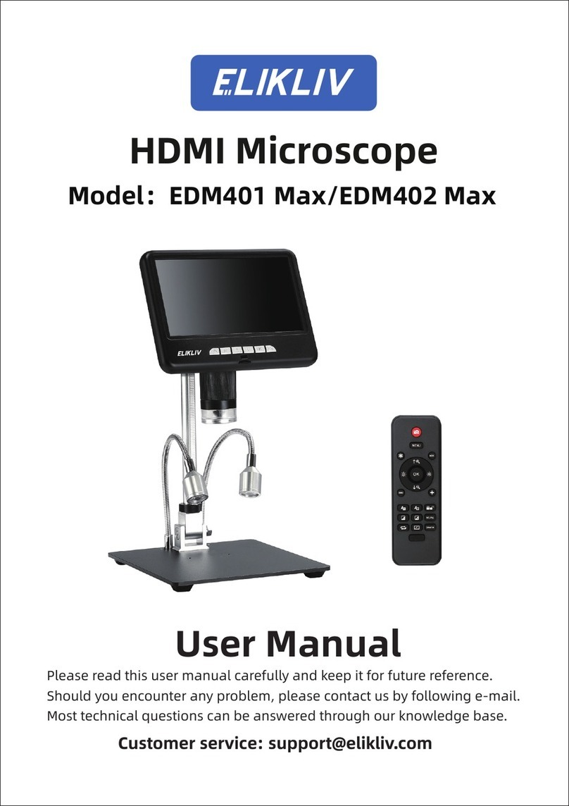
To clarify the terminology/nomenclature used, the following part names are used:
-“LCD”: this is the microscope/LCD assembly
-“Holder”: this is the metal bracket that mounts to the “Stand” on its rear end and into
which the microscope body fits on the front of the “Holder”
-“Stand”: this is the vertical post that the “Holder” & “LCD” raise and lower on
-“Base”: this is the metal plate which supports the “Stand” and the two auxiliary
gooseneck LED lamps
The names of the major parts are listed below:
LCD
-7” diagonal backlit color LCD display, actual image is about 153mm wide
-Microscope with integral lens, surrounded by an annular array of LEDs, and with a
transparent lens protector
-Focusing wheel located just above the bottom end of the microscope
-Battery cover on the rear of the LCD, slides down to open and detach
-Lithium-Ion battery, type 18650, under the battery cover
Holder
-The front ring of the Holder has two small thumbscrews for securing the microscope that
passes through the ring from the top
-Two large magnification adjusting thumbscrews, located at the rear of the Holder, a
pinion gear inside the rear of the Holder engages the rack on the front edge of the Stand
-Magnification adjustment friction thumbscrew, which presses against a friction pad that
slides inside an extruded groove on the rear of the Stand’s post
-
Stand
-The vertical post screws into a threaded hole on the top-rear of the Base, and is secured
using a knurled locking ring (similar to a jam-nut)
-The vertical post has a threaded rack running vertically along the post’s front, which is
engaged by the pinion gear on the Holder

6
Base
-At the top rear corners of the Base are the mountings for the two auxiliary gooseneck
LED lamps
-Under the rear edge of the Base is a plastic enclosure which houses the electronic
dimming circuit for the auxiliary gooseneck LED lamps. A microUSB connector allows
5VDC power to be applied for use by the two lamps. A small knurled brightness control
wheel allows adjustment, from OFF to full brightness, of the two auxiliary lamps. Note
that most of the control’s rotation has no affect on the lamp brightness, with its effective
range being a small portion of the rotation
Light Barrier
-The Light Barrier is a metalized plastic ring that can be used to replace the normal
“transparent lens protector” that normally surrounds the lens.
-The “transparent lens protector” fits tightly, but can be removed from the microscope by
firmly pulling down (away from the body of the microscope) while also using a wiggling
or rocking motion.
-Once the “transparent lens protector” has been removed, the Light Barrier can be attached
to the microscope using a ‘bayonet’ action; press it up against the bottom of the
microscope near the lens, and twist about 45 degrees to lock it in place.
-The function of the Light Barrier is to reduce reflection when using the microscope for
doing micro-soldering, for example of SMD electronic components on a printed circuit
board.

7
Menu
The microscope can be configured in many ways by use of a menu that is integral to the LCD.
-To enter the Menu, press the “M” button on the bottom edge of the LCD, or alternately
press the [M] button on the wired remote control; this will bring up the menu.
Henceforth, this text will simply refer to “M” to mean either of the two buttons described
above.
-The menu is divided into two tabs, one being for camera settings (either Still or Video,
depending on the currently selected mode) and the other being for general microscope
settings; the Camera menu (represented by a camera shaped icon) is the first to be
selected by the above step. Make any desired camera settings and configurations here.
-There are actually three versions of the Menu, and the one you see depends on which
mode the microscope is in: Still, Video, or Playback. The following Menu description is
based on the appearance of the Menu while the microscope is in the Still mode.
-Pressing “M” will change the menu from the Camera to the General Settings menu
(represented by a wrench-shaped icon). Make any desired non-camera settings and
configurations here.
-Pressing “M” again will exit the menu and return the LCD to normal operation.
oUse the ^ and v buttons on either the LCD, or the wired remote, to select options
within each of the two menus.
oPress the “OK” button on the LCD, or the Camera icon/OK button on the wired
remote, to open the currently selected option. Henceforth, “OK” will refer to
either method.
oCamera Settings Menu
[MP] Resolution option applies to still photos. The choices are:
•12M (4032 x 3024 pixels)
•10M (3648 x 2736 pixels)
•8M (3264 x 2448 pixels)
•5M (2592 x 1944 pixels)
•3M (2048 x 1536 pixels)
oUse ^ and v buttons to select the desired resolution, then
press “OK” to select and return to the menu
Burst Shooting option applies to still photos. The choices are:
•Off (default)
•On
oUse ^ and v buttons to select the desired option, then press
“OK” to select and return to the menu
oWhen selected to ON, the microscope will take a series of
five (5) still images in quick succession, 1 second apart,
starting when the button that triggers a picture to be taken
is pressed

8
Image Quality option applies to still photos. The choices are:
•High quality
•Standard (default)
•Economic
oUse ^ and v buttons to select the desired quality, then press
“OK” to select and return to the menu
oThe number of photos at the current resolution that can fit
onto the installed SD card will differ depending on the
image quality selection
Sharpness option applies to still photos. The choices are:
•Intensive
•Standard (default)
•Soft
oUse ^ and v buttons to select the desired sharpness, then
press “OK” to select and return to the menu
ISO (light sensitivity) option applies to still photos. The choices are:
•Auto (default)
•100 (less sensitive to light)
•200 (more sensitive to light)
oUse ^ and v buttons to select the desired sensitivity, then
press “OK” to select and return to the menu
Exposure Compensation option applies to still photos. The choices are:
•+2/3
•+1/3
•+0.0 (default)
•-1/3
•-2/3
•-1.0
•-4/3
•-5/3
•-2.0
oUse ^ and v buttons to select the desired compensation,
then press “OK” to select and return to the menu
Date tag option applies to still photos. The choices are:
•Off
•Date
•Date/Time (default)
oUse ^ and v buttons to select the desired option, then press
“OK” to select and return to the menu
oThis option selects whether or not the date (and optionally
the time of day) will be included as part of the stored/saved
image(s)

9
oVideo Settings menu
[MP] Resolution option applies to videos. The choices are:
•1080FHD (1920 x 1080 pixels)
•1080P (1440 x 1080 pixels)
•720P (1280x720 pixels)
Exposure Compensation option applies to videos. The choices are identical
to those available when in Still photo mode (see above).
Date tag option applies to videos. The choices are identical to those
available when in Still photo mode (see above).
oGeneral Settings menu
Date/Time option
•The internal clock of the LCD is not very accurate, and will likely
need to be adjusted/reset fairly often, unless an accurate ‘Date tag’
(see above) is not required, or if the ‘Date tag’ option is turned
OFF
•Set the Date in one of three formats (see below), one group of
digits at a time, from left to right (the active digits are highlighted)
oBy default, the Date format is YYYY/MM/DD
oUse ^ and v buttons to change the highlighted digits, then
press “OK” to move to the next group of digits; pressing
“OK” after the right-most group, the highlight will move on
to the Time (see below)
•Set the Time, which is always in HH:MM:SS format, one group of
digits at a time, from left to right
oUse ^ and v buttons to change the highlighted digits, then
press “OK” to move to the next group of digits; pressing
“OK” after the right-most group, the highlight will move on
to the Date Format (see below)
•Set the Date Format from one of three choices:
oYYYY/MM/DD (default)
oMM/DD/YYYY
oDD/MM/YYYY
opressing “OK” after the right-most group, the highlight will
move back to the Date (see above)
oTo leave the Date/Time option, press “M”

10
Automatic Shut-down. The choices are:
•Shut [= OFF] (default)
•3 minutes
•5 minutes
•10 minutes
oUse ^ and v buttons to select the desired option, then press
“OK” to select and return to the menu
oThis is a battery saver which optionally will turn the power
off if no buttons are pressed during the selected time period
Screen Protection (= screen-saver/power-down). The choices are:
•Shut [=OFF] (default)
•3 minutes
•5 minutes
•10 minutes
oUse ^ and v buttons to select the desired option, then press
“OK” to select and return to the menu
oThis is a battery saver which optionally will turn the LCD
screen’s backlight off if no buttons are pressed during the
selected time period
oThis option can be turned on while the more general
Automatic Shutdown (see above) is turned off, and thereby
function as a semi-battery saver
oThis option, if turned on, might be confusing because if the
screen goes blank, the user might not be able to easily tell
whether the microscope is turned off, or if it is turned on
but the screen is turned off
Language Selection. The choices are:
•English (default)
•Portuguese
•Simplified Chinese
•Japanese
•French
•German
•Korean
•Italian
•Dutch
•Russian
•Spanish
•Arabic
oUse ^ and v buttons to select the desired option, then press
“OK” to select and return to the menu

11
Light Source Frequency. The choices are:
•50 Hz (default)
•60 Hz
oUse ^ and v buttons to select the desired option, then press
“OK” to select and return to the menu
oThis selection changes the microscope’s operation to
minimize visual artifacts (banding, etc) in recorded videos,
as a result of ‘beat frequency’ interaction with area lighting
which invisibly pulses rapidly according to the AC line
frequency in the part of the world where the microscope is
being used; set according to the local AC line frequency
oThis may also be influenced by, or associated with, the TV
video standard used in the part of the world where the
microscope is being used; the PAL video format is mostly
used where 50Hz AC power is used, and the NTSC video
format is used on many areas where 60Hz AC power is
used
Line Assist. The choices are:
•Off (default)
•On
oUse ^ and v buttons to select the desired option, then press
“OK” to select and return to the menu
oThe purpose of this option is unclear, and is not described
in the DM9 product’s Instruction Manual. However, a
different Instruction Manual for the similar Elikliv DM3
microscope briefly mentions this feature without actually
describing its function
oBy empirical experimentation, this Line Assist option, if
turned on, simply places a crossed pair of vertical and
horizontal red lines on the screen image, something like a
target cross-hair. However, the red cross-hairs do not seem
to be stored as part of the still and video files, so they do
not appear in Playback of still images or videos
Formatting (of the microSD card)
•To use this menu option, there must be a microSD card inserted
into the “TF” slot on the LCD
oSelect Cancel (default) or Confirm
oIf confirmed, it will probably be necessary to re-confirm,
because proceeding will erase all photos and/or videos on
the microSD card
oA message “Hold On” appears while the microSD card is
re-formatted/erased

12
oIt is necessary to use the LCD to format the microSD card
before the LCD will recognize it as a valid memory device
for storage of still image and/or video files; formatting the
SD card in a personal computer will probably result in the
LCD not recognizing the SD card
Default Setting. The choices are:
•Cancel (default)
•Confirm
oIf confirmed, the LCD will set all menu options back to
their defaults
oIf cancelled, all menu options will remain as set by the user
Version
•Pressing “OK” shows the LCD’s current firmware revision level
•Pressing “OK” a second time will return to the menu
oIf there is a method for updating the firmware, it is not
described in the User’s Manual, and is not apparent from
the context of the menu
Selecting the Mode
-Press “M” on the LCD (or “[M]” on the wired remote) for 3 seconds (or, briefly
click/press the [>] button on the wired remote) to cycle between the following three
modes:
oStill (indicated by a camera icon at the upper left of the LCD screen)
oVideo (indicated by a video camera icon at the upper left of the LCD screen)
If the message “No Card” appears when starting to take a still photo or
start recording a video, and yet the SD card icon at the center right of the
screen is showing OK (i.e. no red X on the SD card icon), then remove the
SD card and re-insert it, and try recording the still image or video again
oPlayback (indicated by an [>] icon at the upper left of the LCD screen)
If there is no SD card installed in the LCD, or an improperly formatted SD
card is installed, a message “No File” will appear on the screen

13
To Take a Still Photo
-Select “Still” mode (see above)
-Press the button with the camera icon (or the “OK” button) on the bottom edge of the
LCD next to the “M” button, or press the “Camera/OK” button on the wired remote
-The photo it taken and the message “Hold On” appears while the JPG file is being stored
on the SD card
oThe upper right corner of the screen shows the approximate remaining number of
still photos that can still fit into the remaining space of the SD card, at the current
still photo settings (see Menu)
oJust below the “remaining” number (see above) is an indication of the current
selected still photo resolution, e.g. “8M” (see Menu)
To Take a Video
-Select “Video” mode (see above)
-Using the pushbuttons on the LCD:
oPress the “OK” button on the lower edge of the LCD to start taking the video
oA flashing red dot appears next to the video camera icon at the upper left corner
of the screen, showing that video is being recorded
oA red text time counter number is displayed near the upper center of the screen
oA white text readout appears at the upper right of the screen, showing the video
resolution, e.g. “720P”
oPress the “OK” button to stop recording the current video
-Using the pushbuttons on the wired remote:
oPress the ‘video camera icon’ pushbutton (works like the “OK” button on the
LCD)
oSame details as above
oPress the ‘video camera icon’ button to stop recording the current video
Playback
-Select “Playback” mode (see above)
-While in Playback mode:
oThe most recently taken still image or video will be selected by default
oOn the upper left corner of the screen, there will be either a [>] icon (if the
currently selected file is a still photo) or a ‘frame of movie-film’ icon (if the
currently selected file is a video)
oTo the right is the still photo or video icon described above will be the filename of
the currently selected file; the filename will use yellow text, and will have a .JPG
extension (if still photo) or an .AVI extension (if video)

14
oUse ^ and v buttons to scroll through all recorded files on the SD card
When scrolling, if a still photo file is currently selected, the complete
image will be displayed on the LCD screen, and no other action is required
to view it
When scrolling, if a video file is currently selected, a ‘thumbnail’ image
from the video will be displayed on the LCD screen, and the user can
continue scrolling, or can choose to play the currently selected video:
•Press the “OK” button to start playing the currently selected video
oA time counter with red numbering will appear at the upper
center of the LCD screen
oPressing “OK” again while the video is playing will stop
the playback of that video and return to the thumbnail view
The lower right corner of the LCD screen will show the Date/Time stamp
of the still photo or video, unless the ‘Date tag’ option was turned off in
the Menu. The format of the Date/Time stamp, if present, will show the
information selected for the ‘Date tag’ in the Menu, i.e. Date alone, or
Date & Time
oWhile in Playback mode, briefly pressing the “M” or “[M]” button will call up a
special version of the Menu, with options for deleting a file(s) stored on the SD
card; the choices are:
Delete Current (Still or Video)
Delete All (Stills and/or Videos)
Pressing “M” again will exit this Menu without needing to select either of
the above two options
•If one of the above two options is selected, a verification is
required:
oCancel
oConfirm
oPress “OK” to select either of the above options
If all files have been deleted, a message “No File” will appear on the
screen for as long as the LCD remains in “Playback” mode
There is also an option, encountered in the above menu screens, for
“Protection”:
•Lock Current
•Unlock Current
•Lock All
•Unlock All
oFiles that have been Locked cannot be deleted using the
controls and options on the LCD
oUse this “Protection” menu option again to change the
Lock settings on one or more stored still & video files
oA file that was previously locked, but has been unlocked,
can be deleted using the above Delete menu option

15
Ports
-LCD
o‘DC5V’ jack
This jack accepts a microUSB plug on the end of a USB cable whose other
end can be plugged into various USB power sources, such as a USB AC
Power Adapter/Charger or a USB port on a PC
In order for the LCD to communicate with a PC, there MUST be a USB
cable connected between this jack and a PC
Using the microscope as a stand-alone instrument, and with an adequate
charge on the LCD’s battery, there is no need to connect a USB cable to
this jack
With this jack connected to a USB power source via a USB cable, the
LCD’s battery will be charged
o‘TF’ socket
This socket accepts a microSD memory card
The microSD card must be at least 8GB, and no larger than 32GB capacity
The microSD card must be oriented with its side have writing and text
facing forward (towards the user), and the connectors on the left side as
viewed from the front of the LCD (the serrated edge of the card will be on
to top)
Press the microSD card into the TF socket until it is flush with the edge of
the LCD; a mechanism in the socket should now lock in the SD card – if
the card springs back out, it was not pressed all the way into the socket
Press the end of the microSD card slightly further into the socket, and then
release; a spring mechanism in the socket will eject the card
o‘Key’ jack
This jack accepts the plug on the wired remote control’s cable
On versions of the microscope that have the two auxiliary LED gooseneck
lamps on the Base (such as the DM9 model), the wired remote’s cable
plug will have an additional cable coming out of it, with a microUSB plug
on its other end. This additional cable & plug are intended to provide a
USB power source for the Base’s auxiliary lamps, and the plug will fit into
the microUSB ‘DC5V’ socket on the rear of the Base
o‘[- > +]’ wheel
This wheel allows adjusting the brightness of the microscope’s annular
LED lamp that encircles the lens
Most of the useful adjustment range is within a small part of the wheel’s
rotation; in the rest of the rotation, the annular LED lamp will be off

16
-Base
o‘DC5V’ jack
Any 5V USB power source having a microUSB plug can be inserted into
this jack for the purpose of powering the pair of auxiliary LED gooseneck
lamps
The cable from the LCD’s ‘Key’ jack can be used as the USB power
source for the Base; however, this will deplete the LCD’s battery more
quickly (unless the auxiliary LED lamps are turned off)
o‘[- > +]’ wheel
This wheel allows adjusting the brightness of the Base’s pair of auxiliary
LED gooseneck lamps
Most of the useful adjustment range is within a small part of the wheel’s
rotation; in the rest of the rotation, the auxiliary LED gooseneck lamps
will be off

17
Connecting to a PC
The microscope’s integral camera can be used as a camera for a PC, either Windows or Mac.
Connect a USB cable (having a microUSB plug on one end) into the LCD’s ‘DC5V’ jack. The
PC will now power the microscope. Note that some USB cables only have two wires inside, and
are only useful for providing USB power to devices; make sure to use a USB cable that is fully
wired and thus can be used for USB communications.
On a Windows PC, run the “Windows Camera” or similar function (details of this will vary with
the version of Windows). If the PC does not have this application, it might be necessary to do a
Google search to find a download for “Windows Camera” and install it. With the application
ready in Windows (but not yet running), connect the microscope LCD to the PC, and a menu will
appear on the LCD, showing options for “Mass Storage” (the PC can access the files stored on
the LCD’s installed microSD memory card), “PC Camera”, and “Charging Mode” (where the
PLC is only being used as a USB power source for the microscope, not for communication).
Select the “PC Camera” option and Confirm. Start the “Windows Camera” application on the
PC, and it should detect the microscope and should show a real-time display, and the
microscope’s image can be viewed on the PC, and recorded (still image and video). If the PC’s
“Windows Camera” software does NOT automatically detect the microscope (and there might be
an error message), unplug the USB cable from either the PC or the LCD, and plug it back in
again.
On an Apple PC such as a MacBook or an iMac, make sure that the PC already has the “Photo
Booth” application installed; if not, download it from the Apple ‘App Store’. Connect the
microscope LCD to the PC using a USB cable (it may be necessary to use a USB hub if the PLC
does not have enough USB sockets available). A menu will appear on the LCD, showing options
for “Mass Storage” (the PC can access the files stored on the LCD’s installed microSD memory
card), “PC Camera”, and “Charging Mode” (where the PLC is only being used as a USB power
source for the microscope, not for communication). Select the “PC Camera” option and Confirm.
On the PC, start the “Photo Booth” application (Finder > Application > Photo Booth) and choose
“General – UVC #2 (Default)” on the menu bar.
Note that when the LCD is plugged into a PC via a USB cable, all pushbuttons on the LCD and
the wired remote control are inactive. Use the PC software to interface with the microscope, take
pictures and videos, and optionally access the microscope LCD’s microUSB memory card.

18
Specifications
Subject
Parameter
Model
DM9
Maximum Pixel Resolution
1080 FHD (Full High Definition) / 12MP (megapixels)
Lens Optical Size
1/4”
Photo Resolution
3M, 5M, 8M, 10M, 12M (LCD must be in Still mode to adjust)
Photo Image Format
JPEG (.JPG)
Video Resolution
1080 FHD, 1080 P, 720 P (LCD must be in video mode to adjust)
Video Format
AVI (.AVI)
Focusing Adjustment
Manual, using Focus Wheel on Microscope
Focusing Range
10~40mm (1~4 cm)
Magnification Adjustment
Manual, using two thumbwheels on LCD Holder
Magnification Range
50x~1200x (per brochure), 500/1000 (per manual), see note below
Light Source (Microscope)
8 LEDS in annular arrangement encircling the lens
Light Source (Base)
2x gooseneck lamps, each with 1 LED in a parabolic reflector
White Balance
Automatic
Exposure
Automatic (Exposure compensation adjustable from Menu)
Aperture
F4.5
Lens Structure
2G+IR
Minimum lens-to-subject
Approx. 8mm
Supported Languages
12
PC Image Resolution
640 x 480, 1280 x 720
PC Image Transfer Rate
26 fps
PC Operating Systems
Windows XP, 7, 8.1, 10 and higher (and Apple Mac OS)
A Note on the Magnification
The Amazon listing for this microscope, and the “Instruction Manual” included with the
microscope, both specify the magnification as 50x minimum and 1200x maximum, a ratio of
roughly 24. By contrast, the “Instruction Manual” specifications page gives the ‘magnification’
as “500/1000”, a ratio of 2; a big difference between this and 24!
The author of this “Enhanced User’s Manual” has done empirical evaluation of the actual
magnification. A thin metal ruler with 1mm graduations was placed on the Base and the
microscope’s “transparent lens protector” was lowered until it touched the ruler, then the focus
wheel was adjusted for a clear image on the LCD screen. A distance of approximately 2.14mm
on the ruler was magnified to take up the entire width of the screen. Then the microscope was
raised on its stand as high as it would go, and the image was focused once more. Now a distance
of approximately 14.5mm was magnified to take up the entire width of the screen. This gives a
ratio of about 6.8, again quite different from the ratios of 24 and 2 given in the “Instruction
Manual”. Based on these measurements, the microscope’s maximum magnification, subject-to-
screen (the screen is 153mm wide), is 153/2.14 = 71.5x, and the minimum magnification is
153/14.5 = 10.5x ….. so the magnification specification SHOULD BE 10.5x ~ 71.5x.
Table of contents
Other Elikliv Microscope manuals
