manuals.online logo
Brands
  1. Home
  2. •
  3. Brands
  4. •
  5. Olympus
  6. •
  7. Microscope
  8. •
  9. Olympus CHA-P User manual

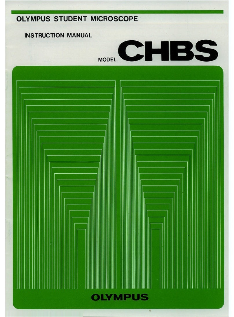
Olympus CHA-P User manual

OLY
MPUS
POLARIZING
MICROSCOPE
I
INSTRUCTION
MANUAL
I
,(
MODEL
-
I
I
OLYMPUS
This
Instruction
manual
has
been
written
fartbs
use
of
the
Otympus
Polarizing
Micro-
mpe
Madel
CHA-F.
It
is
recommended
to
read
the
manual carafully
in
order
to
familierlze
youmlf
fully
with
the
USB
af
the
mimompeon
the
polarizing
attachment
IMPORTANT
-we
tlta
following
points
carefully:
1.
Always
handle the
microscope
with
the
care
it
deserves,
and
avoid
abrupt
motions.
2.
Avoid
exposure
of
the
microscope
to
direct
sunlight,
high
temperature
and
humidity,
dust
and
vibration.
If
the
microscope
is
used
in
ambient
temperature
higher
than
40'~
(104~~1,
it
ma
impede
its proper
function.
3
3.
Only
use
the
tension
adjustment
ring
for
atbring
the
tension of
the
coarse
adjustment.
Do
not
twist
the
two
coarse
adjustment
knobs in
the
opposite
directions
simultane-
ously,
which
might
cause
damage.
4.
Ascertain
that
the
line
voltage
selector
switch
on
the
base
plate
is
set
to
conform
with
the
local
mains
voltage.
1.
Lenses
must
always
i3e
kept
clean.
Fine
dust
on
lens
surfaces
should
be
blown
or
wiped
off
by
maam
of
an
air
blower
or
a
clean
brush.
Carefully
wipe
off
oil
or
finger-
prints
deposited
on
the
lens
sutfaces
with
gauze
moistened
with
a
small
amount
of
xylem,
alcohol
or
ether.
2.
Do
not
use
organic
solutlans
to
wipe
the
surFaces
of
various
camponants.
Plastic
parts,
especially,
should
be
cleaned
with
a
neutral
devteqent.
3. Never
diassemble
the
microscope
for
repair.
4.
The
miwascope
should
be
stored
in
its
container
immediately
after
uw.
If
this
is
not
possible,
it
should
be
mered
wivth
a
vinyl
dust
mr.
5.
Disconnect
the
line
cord
from
the
AC
power
source
kfore
fuse
replament.
CONTENTS
.....................................
I
.
STANDARD
EQUIPMENT
It
.
NOMENCLATURE
..........................................
In
. ~EMBLY
..............................................
N
. lDENTlFlCATlON
AND
FUNCTION
OF
VARIOUS
COMPONENTS
........
V.
OPERATION
..............................................
1
.
Adiustment
of
Minimum
Line
Voltage
2
.
lnterpupillary
Distance
and
Diopter Adjustments
......................................
.
3
Polarirer
Alignment
8
......................................
.
4
Centering
the
Stage
g
5
.
Centering
the
Objectives
6
. Use
of
Apenure
Irk
Diaphragm
.....................................
7. Focusing
Adjustment
10
8
. Orthosoopic
Observation
9
.
Conompic
Observation
...................................
11
............................................
Vl
. OPTICALDATA
12
........................................
VII
.
TROUBLESHOOTING
13
I.
STANDARD
EQUIPMENT
Model
Component
Microscope
stand
with
circular
rotatable
CHA-P-F
stage
and
quadruple
nmpiem
Intermediate
polarizing
attachment
AH-PA
Quarter
wave
plate
(retardation
1
47.7.3W
AH-TP147
SenltFw
tint
plate
(retardation
Wnyr)
AH-TP530
Polarizing
monocular
tube
(45")
CH-PMO
Polarizing
binocular
tube
(30°)
BH-PSI
Swing-out
polarizing
condenser
BH-PUC
Haim
lamp
socket
CLSH-B
Halogen
bulbs
BVIOWHAL
CHA-Pal
1
I
I
1
I
0
1
1
2
1
1
1
0
1
2
t
Objectives
(strain-f
reel
Evepieces
CHA-Pa1
1
1
1
1
0
1
1
1
2
1
1
1
1
1
2
1
PO
4x
W10X
P040X
AH-WF1OX
AH-Miwo
WF
1
QX
Spare
fuses
(MA
for
1110-1
113-12DV
or
0.3A
for
220-24\11
Vinyl
dust
cwer
I.
NOMENCLATURE
Photo:
Model
CHA-P-651.
Model
CHA-P-051
is
also
available
by
modification
of
som
components.
axmatior,
tube
Revolving
nosepiece
Intermediate
pojwiaing
atmhmt
Objective
Microscope
stand
Condenser
1
Ill.
ASSEMBLY
The
picture
balow
illustrates
the
sequential
procedure
of
assembly.
The
numbers
indicate
the
assembly
order
of
various
components.
Remove
dust
caps
before
mounting
components.
Take
care
to
keep
all
glass
surfaces
ctean,
and
avoid
watching
the
surfaces.
Insert
tha
obbctb
10X
into
@
Eyepiece
the
fixed
aperture
of
tha
nos-
P-.
Clamping
screw
Quarter
wave
plete
Sensitive
tint
plate
with
the
lettEtrs
"OLYMPUS'
facing
in
front
of
the
mi-
Clamping
screw
Microscope
stand
Condenser
@
To
AC
outlet
Q
Q
0-0
/
Halogen
lamp
Socket
Aligning
red
dots,
on
con-
denser
mount
and
condensas,
in-
the
conderuar
Into
the
IV.
IDENTI
FlCATlON
AND
FUNCTION
OF
VAR
lOUS COMPONENTS
Observation
rube
clamping
screw
P
Main
switch
R
hmat
trimmer
screw
After
swltchlno
on.
M
nmry,
r-te
this
wrew
wlth
a
coin
until
tb
bulb
18
dimly
Ilt,
with
the
sliding
cmtrol
lrmrr
at
mlntmum
0mltIon.
\
Grounding
terminal
/
Line
volw
selector
switch
Set
the
swltch
to
conform
with
the
1-1
mains
volmp.
Mechanical
tube
length
adjust-
ment
rings
Bertrand
tens
turret
ring
W
llght
path;
"OUT"
for
remmal
of
the
Barwand
lens
I
from
the
li&t
path.
Bertrand
lens
focusing
ring
Stage
centering
screw
Automatic
pre-fowsing
lever
Aperture
iris
diaphragm
ring
Numerial
aperture
sale
grrd-
Swinwut
knob
for
top
lam
Codewer
M.A.
Is
0.9
(when
top
lms
swln$s
out
N.A.
k
0.251
Film
mount
Amwe
45rnmdlm
f
llters.
Bulb
mount
\
Lamp
house
clamping
knob
The
lamp
how
cow
Ean
twr
opened
by
pulllw
down
th
kn&:
or
cl-
by
pushing
it
up
untll
it
snaps
In
plaes.
More
pushing,
escertaln
that
the
knob
is
positiQned
aa
shm
in
the
picture
rlght,
markd
wilh
Match
the
line voltage
selector
switch
to
Imal
mains
voltage
(se
page
5).
Switch
on
the
light
source.
Adjust
the
trimmer
screw
until
the
bulb
is
dimly
lit
(page
7).
Place
a
spacimn
slide
on
the
stage.
Remove
the
Bertrand
lens
and
analyzer
from
the
light path.
Coarse
focus
with
the
1
OX
objective.
Make
interpupillary
and
diopter
adjustments
(paga
7).
Center
the
stage
(page
9).
Cenw
objectiw
other
than
10X
(page
9).
Swing in
the
desired
objective.
Set
the
condenser,
analyzer
and
Bertrand
lens
mrrectly
according
to
your
microscopic
purpose
(page
1
0
and
11).
Adjust
light
intensity.
Fine
focus.
Adjust
aperture
Iris
diaphragm
{page
9).
Adjustment
of
Illumination
System
For
biological
use,
however,
remove
the
analyzer,
Bertrand
lms
and
sensitive
tint
plates.
Microampic
rnethd
Ohosm~ic
oWation
ConmopIa
observation
*
Cut
off
this
paae
at
dotted
line
and
put
it
on
the
wall
near
the
microscop
for
use
as
a
re-
minder
of
microscopic
procadure.
OLYMPUS
Obiective
4X
,WX
20x
to
i~ax
Bmrand
lens
OUT
IN
Condenmr
top
lens
OW
IN
V.
OPERATION
1.
Adjustmm
of
Minimum
Line
Voltage
'
The
mhirnurn
vol-
quired
for
the
light
source
can
be
adjusted
with
the
rheostat
trim
mer
smw
a?
the
microscope
bas
plate
in
accordanw
with
the
line
voltage
and
frequency.
The
built-in
rheostat
incorporates
a
thyristor
in
itssemiconductor circuit
for
the
following
advantages:
(a)
Extredy
fine
adjustment
of
light
intensity
mn
be
easily
achied.
(b)
Flickering
of
the
bulb
filament
is
eliminated
and
the
light
inmnsity
is
stabilized.
(cJ
Increased life
exp$ctanw
of
th~
bulb.
For
adiustment
of
the
minimum
line
voltam,
ascartain
that
the
voltage
selector
switch
is
E&
to
inform
with
the
Iml
mains
voltaw,
and
the
sliding
control leuera
is
positioned
closest
to
you
(low
voltage),
and
then
activate
the
main
switch
Q.
If
the
bulb
Is
dimly
lit,
the
secondary
voltage
is
correct.
If
it
is
not
lit
at
all,
rotate
the
rheostat
trimmer
screw
@
gradually
with
a
win,
until
the
bulb is
dimly
lit;
then
push
the
stiding
control
lever
forward
in
order
to
obtain optimum
light
intensity. (Fig.
1)
Fig.
1
2.
Interpupiltary
Distanm
and
Diopter
Adjmnis
1)
Insert
lhe
evwieae
@
with
cross
hairs
into
the
right
eyepiem
tube
of
the binocular
tub,
aligning the
-,
positioning
slot
Q
and
positioning
an
@
i~i~
21
11
*
When
the
eyepiace
positioning
pin
is
insem
into
the
Ioww
dot
on
the
tuba,
tha
m
lines in
the
eyepieca
coincida
with
the
vibration
direction
of
polarizer
and
analyrer
at
0'
settings.
When
In-
into
the
other
slot,
the
mass
lines
am
at
4g
to
the
direction
of
vibration.
(This
is
the
same
with
the
monwlar
tube.)
Fig.
2
Them
iwrt
the
eyepiece
into
the
left
tube.
2)
Looking
through
the
right
eyepiece
(with
cross
hairs)
with
your
right
eye,
rotate
the
diopter
adjustment
ring
@
until
the
cross
hairs
are
sharply
focused.
(Fig.
3)
3)
Looking through
the
both
eyepiems
with
both
eyes,
adjust
the
lnterpupillary
distance,
sliding
the
knurled
dovetail slid-
@
of
the
right
and
left
eyepiece
tube,
until
parfect
binocular
vision
is
obtained.
4)
Memorize
your
interpupillary
distanm
wring
by
reading
the
scale
@.
Fig.
3
5)
Rotate
the
tube
length
adjustment
ring
@
on
the
right
eyepiece
tube
to
match
your
interpupillary distance
wtting
which
you
obtained
from
the
scale.
5)
Look
at
the
image
through
the
right
eyepiece with
your
right
eye
and
focus
on
the
specimen
with
the
coarse and
fine
adjustment
knobs.
7)
Look
at
the
image
#rough
the
left
eyepiece
with
your
left
eye
and
rotate
the
tube
length
adjustment
rhg
@
to
fucm
on
the
specimen
without
using
the
coarse
and fine
adjust-
ment
knobs.
3.
Polariter
Alignment
1)
Push
the
analyzer
@
into
the
light
path,
and
maki
sure
that
bod1
polarizer and
analyzer
are
set
at
posi-
tion
"0"
to
attain
the
"Crossed
filter"
position.
Then
loosen
the clamping
screw
Q
of
the
condenser.
(Fig.
4)
2)
Rem*
the
specimen
out
of
the
light
path
so
that
a
transparent area
comes
into the light
path.
Kwping
the
polarizer at
the
"0"
position,
rotate
the
polarizer
rotation
ring
@
until
the
optimum
extinction
Is
obtained,
then
clamp
the
ring.
(Fig.
4)
Fig.
4
4.
Cenbring
aha
Stage
1
1
Lmking
through
the
eyepi-
and
ob-ive
IOX,
determine
some
pwtlarbr
point,
s
you
like,
In
the
specimen
image
and
coincide
this
point
with
the
center
of
the
cross
hairs
of
the
eyepiece.
2)
Rotating
the
stage,
coincide
the
center
of
the
rotation
of
a
specimen
pojnt
with
the
can-
ter
of
the
crass
haln
by
means
of
the
two
centering
screws
Q.
(Fig.
5)
*
Repear
this
prcicdwe
untif
the
mation
is
seaid.
Circular
path
of
5.
antaring
the
O$@tim
This
centration
is
required
for
all
PO
objectives
except
the
objective
PO
1
OX.
1)
Imrt
a
centering
wrench
into
each
centering
swew
of
the
nosapiece.
(Fig.
8)
C
2)
By
means
of
the
two
centering
wrenches,
coincide
the
center
of
the
GTW
hairs
to
the
rotation
center
of
the
specimen.
I
3)
After
all
objectives
are
centered,
remove
the
centering
wrenches.
6.
Clae
of
Aperture
Iris
Diaphragm
Adjust
the
opening
of
the
aperture
iris
diaphragm
mrding
to
various
conditions
such
as
the
numerical
aperture
of
.th
objective,
imas
contrast,
depth
of
focus,
and
f
latna
of
field.
Generally
it
is
aften
prefem
bk
to
stop
dwvn
the
aperture
iris
diaphragm
to
70$6
or
80%
of
the
N.
A.
of
the
objectiw.
After
the
eyepisce
is
mrn&
from
the
&sewation
tube,
if
necmary,
look
through
the
observation
tube
and
check
the
opening
of
the
aperture
diaphragm
at
the
objectiw
pupil.
Fig,
6
7.
Focusing
Mjusfment
1)
Tension
adjustment
of
coarse
adjustment
knobs
A
Wnsion
adjustment
ring
@
is
pmvidd
next
to
the
right
hand
coarse
adjustment
knob.
With
this
device
-r--l$
-
'
the
tension
of
the
maw
adjustment
is
freely
adjust-
able
for
either
heavy or
light
movement
depending
on
1.
5;
operator
preferma.
(Fig.
7)
However,
do
not
loom
the
tension
adjustment
riw
too
much,
becausa
the
stage
drops,
or
the
fins
ad-
justment
knobs
slip
easily.
-
--
.
t
Fig.
7
f
Be
carefut
not
to
mtate
the
right
and
I&
mrsa
adjustment
knobs
in
the
opposite
directions
simul-
tanerwdy.
2)
Pre-focusing
Iever
Crr
This
lewr
@
Is
locked
after
mars
focus
has
hn
aecompiistaed.
It
prevents
further
upward
travel
of
the
stqe
by
means
of
the
warse
adjustment
knobs,
and
automatically provides
a
limiting
stop
if
the
stage
is
lowered
and
then
raised
again.
(Fig.
81
8.
Orthaseodc
Observation
Fig.
8
1)
Swing
out
the
top
lens
of
the
condenser.
In
princfple, polarized
light
enters
the
light
path
paraitel
to
the
optical
axis,
to
enable
obsewatjon
of
the
optical
characteristics
of
the
mimen.
Howww,
this
method
will
darken
the
field
of
view
and
lower
the
resolving
power
of
the
objective
extremely.
Them
fore,
swing
out
the
top
bns
of
the
mndenser,
using
only
the
lawer
aperture
of
the
lower
cundenser
lens.
2)
Insert
the
analyzer into
the
light
path,
and
attain
crossed
filaer
position
with
analymr
and
polarizer
at
o0
setting.
At
this posltion,
the
polarizer
vibration
is
in
the
nortbouth
direction, and
the
analyzer
vibration
in
the
east-west
direction.
To
open
the
fik
posi-
tion,
pull
out
the
analyzer
roQtion
m.
3)
Rotate
the
stage
until
extinction
of
the
image
is
attained.
From
this
position,
rotate
the
by
45'
to
obtain
the
diwnal
posi'tion,
at
which
position,
the
retardationangle
is
mured.
4)
Insert
the
quarter
wave
plate
or
sensitive
tint
plate
into
the
slot
in
the
intermediate
polarizing
tube.
*
A
Berek
compensator
is
optionally
available
to
measure
the
birefringence
of
a
specimen.
Sensitha
tint
pbts
-
Quarter
warn
plata
7)
Swing
in
the
top
lens
of
the
.wndenser,
and
illuminate
the
mcirnen
with
no
nmd
to
irnmerm
betwen
the
condenser
and
specimen
slide.
2)
Bring
the
specimen
inlo
foeus,
rotate
the
Bertrand
lens
turret
ring
into
the IN
position.
3)
Focus
on
the
interferenw
figure
formed
at
the
back
fowl
plane
of
the
objectimfrom
20X
to
1wx.
The
pinhob
cap
provided
may be
used
in
place
of
the
eyepiem
to
dimly
view
the
interference
figure
m~ntioned
above,
In
this
case,
the
Bertrand
lens
is
disengaged.
VI.
OPTICAL
DATA
Immersion
objective.
Resolving
power
is obtained
when
the
objective
is
used
at
full
aperture
diaphragm.
ObJective Magnification
P04X
P010X
W20X
P040X
*W100X
0.10
0.25
0.110
0.65
1.30
W.
D.
(mm)
18.77
6.78
1
-58
0.61
0.1
1
Fwl
length
(mml
28.45
16.08
8.1
3
4.33
1.81
Resolving
pwver
(id
3.4
1.3
0.84
0.52
0.26
(Spring
(Spring
loaded)
loaded)
Tk
eyepieces
K5X
and
WFlOX
incorporate
a
sliding
eye
shield.
This shield
can
be
pulled
our
to
prevent
glare
and
loss
of
contrast
caused
by
ambient
tight
hitting
the
we.
K5X
(Field
number
21)
WFlOX
(18)
0
W.D.
(Working
distance):
The
distance
benveen
the
swimen
crr
cover
glass
and
the
nearsst
point
of
the
objective.
0
N.A.
(Numerical
aprture):
The
numerical
aperture
represents
a
performance
number
which could
be
compared
to
the
relative
aperture
(f-number)
of
a
camera
lens.
M.A.
values
can
t~
used
for
dimtly
comparing
the
mlving
powers
of
all
types
of
objectives.
The
larger
N.A,
the
higher
the
resolving
power.
Total
magnification
Focfll
demh
IN)
Field
of
view
Irnrn)
Total
magnification
Focal
depth
(p)
Field
of
viaw
(mm)
0
Resolving
power:
The
ability
of
a
lens
to
register
small
details.
The
resolving
power
of
a
tens
is
measured by
its ability
to
separate
two
points.
0
Foal
depth:
The
distance
between
the
upper
and
lower
limits
af
sharpness in
the
image
fond
by
an
optical
system.
20X
300.0
5.25
40X
172.6
4.5
0
Field
number:
A
number
that
represents
the
diarne'ter
in
mm
of
the
image
of
the
field
diaphragm
that
is
ford
by
the
lens
in
front
of
it.
0
Field
of
view
diadar:
The
actual
size
of
the
field
of
view
in
mm.
50X
48.0
2.1
1KiX
27.60
1.8
lOOX
t
556
1.05
200X
9.19
0.9
200X
4
.W
0.53
400X
3.03
0.45
500X
1.05
0.21
1,000X
0.66
0.1
8
Troubles
Causes
Remedies
1.
Optical
System
(a)
With
the
illuminator
The
condenser
is
lowerd
exces-
Raise
the
condenser to
the
upper
switched
on,
the
field
sively.
limit.
of
view
cannot
be
seen.
Analyzer and polarizer
are
in
the
Set
them
at
the
position
"0:90"
or
"crossed
filter"
position
("0:O").
*'90:0".
(bl
The
field
of
view
is
cut
The
nosepiece is
not
click
stopped.
Slightly rotate the
nosepiece
until
off
or
illuminated
irreg- it
clicks
into position.
ularly.
The
condenser
is
not
correctly
Re-in~rt
the
condenser
all
the
way.
mounted
on
the
ring
mount.
The sensitive
tint
plate is stopped
Push
the
plate all
the
way
until
it
midway. clicks.
In
case
of
orthoscopic
observation,
Swing
it
out
of
the light
path.
the
condenser
top
lens
stays
in
the
light
path
or
stops
midway.
(c
1
Dust
or
dirt
is
visible
in
Dust
or
dirt
on
the
glass
surface
at
the field
of
view.
the light
exit
on
the
base.
Dust
on
condenser
top lens.
Clean
off
the
dust
or
dirt.
Dirty
specimens.
Dust
on
eyepiece.
(d)
Excessive imagecontrast.
She
condenser
is
lowered
exces-
Raise the condenser.
sively.
The
aperture
iris
diaphragm
is
stop-
Open
the
diaphragm.
ped
down
excekively.
(e)
Resolution problems:
The
objective
is
not
correctly posi- Slightly rotate
the
nosepiece
until
0
Image
is
not
sharp.
tioned
in
the
lighf
path.
it
clicks into
position.
0
Insufficient contrast.
0
Image
details
lack defini-
Dirt
on
objective front lens.
Clean
the
objective.
tion.
The
immersion objective
is
used
Apply
immersion
oil.
without immersion oil.
Bubbles
in
the
immersion
oil.
Remove
bubbtes.
The
Olympus designated
oil
is
not
Use
the
designated
oil.
used.
Remedies
Troubles
Dirty specimen.
Dust
on
condenser lens.
Causes
Clean.
(f)
The
field of view is par-
tially
out
of
focus.
The
specimen
is
not correctly posi-
tioned
on
the
stage.
The
objective
is
not correctly
po-
sitioned
in
the light path.
Place
the
specimen on
the
stage
and
secure
it
with the specimen clips.
I
(g)
The
image
goes
out
of
focus
eccentrically.
Slightly rotate
the
nosepiece until
it
clicks into position.
(h)
When objectives are
changed,
they
are
not
parfocal.
The
objective
is not correctly posi-
tioned
in
the light path.
(
i)
Light intensity
does
not
increase although the
voltage is raised.
I
(k)
No
conoscopic image
can
I
The
condenser top lens
is
not in
(
Swing
it
in.
Stightly rotate the nosepiece until
it
clicks into position.
The
mechanical
tube
length is not
correctly adjusted.
(
j)
The
condenser
does not
come
to
the
correct
posi-
tion for optimum extinc-
tion.
Adjust with the tube length adjust-
ment rings on
the
observation tube.
The
condenser
is
lowered
exces-
sively. Raise the condenser.
1
The
observation tube and mndens-
er are not correct1
y
mounted.
I
be
seen.
1
1
(I) The crossed fiiter posi
2.
Electric
System
Re-mount them correctly.
1
tion is not attained.
the light path.
The
analyzer
is
out
of
the light
path.
Push
it
in.
I
I
I
(a)
The
illuminator is too
I
bright
(or
too
dark).
The
mains voltage is too high
(or
too
low).
The
rheostat
trimmer screw
is
not
matched
to
the
mains voltage.
Adjust the
mains
voltage
with
a
variable
voltage
transformer.
The rheostat trimmer screw is not
correct
lv
adjusted.
Adjust the trimmer screw to
match
the
mains voltage.
Adjust
it
correctly.
(b)
Output voltage
for
the
il-
luminator cannot
be
reg-
ulated.
The voltage selector switch is not
matched
to
the mains voltage.
The
mains voltage
is
too low
or
too
high.
Adjusr
the
mains
voltage
selector
I
switch to the mains voltage.
Adjust
the
mains voltage with
a
variable voltage transformer,
1
Troubles
(c)
The
light flickers and
the
intensity is unstable.
-
-
Causes
I
The voltage
selector
switch is
not
Match
the switch to
the
mains
matched
to
the mains voltage. voltage.
Remedies
-.
The
mains
voltage
is
unstable.
The
filament of
the
bulb
is
likely
to
burn
out.
(d)
Fuse
burns
out
toooften.
(el
Reduced
bulb
life
Use
a
variable voltage transformer.
Replace the
bulb.
I
I
Loose
electrical connection. Secure
the
connection.
The
fuse
is
not
a
standard
fuse.
1
Mains voltage
is
too
high.
1
Use
variable voltage transformer.
Use
a
standard
fuse.
-
The
voltage
selector switch is
not
matched
to
the
mains
voltage.
i3.
Focusing
I
1
Match
the
selector switch
to
the'
mains voltage.
The
bulb
is
not
a
standard
bulb.
I
Use
a
standard
bulb.
I
The
user
is
trying to raise
the
stage
I
,
over
the upper
focusing
limit
imposed
by
the
engaged pre-focus-
ing
lever.
1
{a)
Coar~adjustment is
too
1
Tension adjustment ring is tighten-
Loosen
the
tension
adjustment
ring
I
tight.
ed
too
much.
Unlock
the
pre-focusing lever.
I
properly.
(b)
The
stage drops
and the
specimen
goes
out
of
focus.
Tighten
the
ring properly.
I
The
tension
adjustmer~t
ring
is
too
loose.
{c)
The
stage
cannot
be
raised
to
the upper limit.
Raise
the
condenser
mount
((dl
The
stage cannot
be
low-
I
ered
to
the
lower limit
of
the
working
range.
Pre-focusing
lever is engaged
in
lower than focusing position.
The
condenser
mount
is
lowered
too
much.
4.
Observation
Tube
I
I
Unlock
the
pre-focusing lever.
{e)
The
objective
front
lens
hits
against
the
specimen.
(a1
Incomplete binocular
vi-
lnterpupillary distance is
not
cor- Correct
the
interpupillary
distance.
sion.
rectly adjusted.
--
I---
LA
The
specimen is
mounted
on
the
stage
upside
down.
Reverse
the
specimen.
Remedies
Complete
the
diopter
adjustment.
Use
pair
of
matched
eyepieces.
Prior
to
looking
at
the
image
of
the
specimen,
try
to
look
at
a
far
away
object.
Troubles
Causes
Diopter
adjustment
is
incomplete.
Right
and
left
eyepieces
are
not
matched.
The
user
is
unaccus?omed
to
binocular
observation.
5.
Stage
Clamp
the
stage
securely.
Adjust
the
specimen
position.
(a
1
The
image
easily
goes
out
of
focus
when
you
touch
the
stage.
(b)
The
specimen
stops mid-
way
on
the
east-west
traverse.
The
stage
is
not correctly
clamped.
The
specimen
is
not
correctly
posi-
tioned
on
the
stage.

Other manuals for CHA-P

1

Other Olympus Microscope manuals

Olympus DSX1000 User manual

Olympus

Olympus DSX1000 User manual

Olympus FLUOVIEW FV300 Installation guide

Olympus

Olympus FLUOVIEW FV300 Installation guide

Olympus Lext OLS3100 User manual

Olympus

Olympus Lext OLS3100 User manual

Olympus BX53 User manual

Olympus

Olympus BX53 User manual

Olympus IX71 User manual

Olympus

Olympus IX71 User manual

Olympus SZX9 User manual

Olympus

Olympus SZX9 User manual

Olympus BXFM Series User manual

Olympus

Olympus BXFM Series User manual

Olympus V60 User manual

Olympus

Olympus V60 User manual

Olympus Fluoview FV1000 Manual

Olympus

Olympus Fluoview FV1000 Manual

Olympus VS120 User manual

Olympus

Olympus VS120 User manual

Olympus DP71 User manual

Olympus

Olympus DP71 User manual

Olympus CX41 User manual

Olympus

Olympus CX41 User manual
Olympus DSX510 User manual

Olympus

Olympus DSX510 User manual

Olympus BX-RFAA User manual

Olympus

Olympus BX-RFAA User manual

Olympus BX3-URA User manual

Olympus

Olympus BX3-URA User manual

Olympus CX33 User manual

Olympus

Olympus CX33 User manual

Olympus IMT-2 User manual

Olympus

Olympus IMT-2 User manual

Olympus CX31 User manual

Olympus

Olympus CX31 User manual

Olympus BHS User manual

Olympus

Olympus BHS User manual

Olympus BX-FLA User manual

Olympus

Olympus BX-FLA User manual

Olympus CX41 Installation guide

Olympus

Olympus CX41 Installation guide

Olympus bx40 User manual

Olympus

Olympus bx40 User manual

Olympus SZ2-ILA User manual

Olympus

Olympus SZ2-ILA User manual

Olympus BX3-SSU User manual

Olympus

Olympus BX3-SSU User manual

Popular Microscope manuals by other brands

Celestron Professional 44108 instruction manual

Celestron

Celestron Professional 44108 instruction manual

Zeiss LSM 510 Inverted Brief Operating Manual

Zeiss

Zeiss LSM 510 Inverted Brief Operating Manual

Denville Scientific M3100 Series Operation manual

Denville Scientific

Denville Scientific M3100 Series Operation manual

Hydac MM-KKE-M-C-U Operating and maintenance instructions

Hydac

Hydac MM-KKE-M-C-U Operating and maintenance instructions

Hitachi HF2000 TEM Operation manual

Hitachi

Hitachi HF2000 TEM Operation manual

Meiji Techno MX7500 Series instruction manual

Meiji Techno

Meiji Techno MX7500 Series instruction manual

KERN Optics OBN-13 User instructions

KERN Optics

KERN Optics OBN-13 User instructions

Haag-Streit BM 900 Instructions for use

Haag-Streit

Haag-Streit BM 900 Instructions for use

Labomed CZM6 user manual

Labomed

Labomed CZM6 user manual

Optika Italy IM-3 Series instruction manual

Optika Italy

Optika Italy IM-3 Series instruction manual

Eschenbach 33208 user manual

Eschenbach

Eschenbach 33208 user manual

TOMLOV DM201 user manual

TOMLOV

TOMLOV DM201 user manual

Levenhuk LabZZ MTB3 user manual

Levenhuk

Levenhuk LabZZ MTB3 user manual

National DS-2 instructions

National

National DS-2 instructions

KERN Optics OIV-6 User instructions

KERN Optics

KERN Optics OIV-6 User instructions

KERN Optics OZL 46 Series User instructions

KERN Optics

KERN Optics OZL 46 Series User instructions

insize ISM-DLC120 Operation manual

insize

insize ISM-DLC120 Operation manual

Unitron Z12 manual

Unitron

Unitron Z12 manual

manuals.online logo
manuals.online logoBrands
  • About & Mission
  • Contact us
  • Privacy Policy
  • Terms and Conditions

Copyright 2025 Manuals.Online. All Rights Reserved.