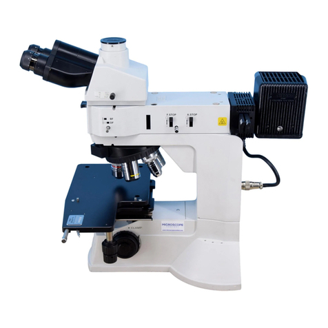
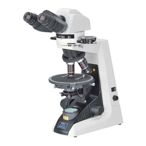
Nikon Eclipse E400 POL User manual

rizing
Micr
ECLIPSE
E400
POL
Instructions


Thank
you
for
purchasing
the
Nikon
products.
This
instruction
manual
is
written
for the
users
of
the
Nikon
Polarizing
Microscope
ECLIPSE
E400
POL.
To
ensure
correct
usage,
read
this
manual
carefully
before
operating
the
instrument
е
It
is
prohibited
to
reproduce
or
transmit
this
manual
in
part
or
whole
without
Nikon's
expressed
permission.
*
The
contents
of
this
manual
are
subject
to
change
without
notice.
*
Some
of
the
products
described
in
this
manual
may
not
be
included
in
the
set
you
have
purchased.
*
Although
every
effort
has
been
made
to
ensure
the
accuracy
of
this
manual,
if
you
note
any
points
that
are
unclear
or
incorrect,
contact
your
nearest
Nikon
representative.
m
Warning/Caution
Symbols
Used
in
This
Manual
us
ein
Although
Nikon
products
are
designed
to
provide
you
with
the
utmo:
lety
during
use,
incorrect
usage
or
disregard
of
the
instructions
can
cause
personal
injury
or
property
damage.
For
your
safety,
read
the
instruction
manual
carefully
and
thoroughly
before
using
the
instrument.
Do
not
discard
this
manual
but
keep
it
near
the
product
for
easy
reference.
In
this
manual,
safety
instructions
are
indicated
with
the
symbols
shown
below.
Вс
sure
to
follow
the
instructions
indicated
with
these
symbols
to
ensure
correct
and
safe
operation.
Symbol
Meaning
WARNING
—
Distearding
instructions
marked
with
this
symbol
may
lead
to
death
or
serious
injury.
A
CAUTION
—
Disreganding
instructions
marked
with
this
symbol
may
lead
to
injury
or
property
damage.
Meaning
of
Symbols
Used
on
the
Equipment
Symbol
Meaning
Caution
for
heat.
A
This
marking
on
the
lamp
cover
calls
your
attention
on
the
following:
*
Lam
cover
becomes
very
hot
during
and
immediately
after
the
illumination.
©
Risk
of
burns.
Do
not
touch
the
lamp
cover
during
and
immediately
after
the
illumination.
•
Make
sure
that
the
lamp
cover
is
sufficiently
cool
before
the
lamp
replacement.

Z\warninc
1.
Intended
product
use
This
microscope
should
only
be
used
for
microscopic
observation.
Do
not
use
it
for
any
other
purpose.
.
Do
not
disassemble
Disassembling
may
cause
malfunction
and/or
electrical
shock.
Do
not
disassemble
any
parts
other
than
those
mentioned
in
this
manual.
If
you
notice
any
malfunction,
notify
your
nearest
Nikon
representative.
Input
voltage
Make
sure
that
the
input
voltage
indicated
on
the
back
panel
of
the
microscope
is
the
same
as
your
regional
voltage.
If
not
the
same.
do
not
use
the
microscope;
instead,
notify
your
nearest
Nikon
representative
immediately.
If
the
microscope
is
used with
the
wrong
input
voltage,
a
short
circuit
or
fire
may
result,
causing
the
damage
of
the
microscope.
Power
cord
To
prevent
electrical
shock,
always
turn
off
the
power
switch
(flip
it
to
the
ide)
before
connecting
or
disconnecting
the
power
cord,
Use
only
the
following
power
supply
cord
set.
Using
the
wrong
power
cord
could
result
in
damage
or
fire.
*
For
100-120V
area
UL
Listed,
detachable
cord
set,
3
conductor
grounding
type
SVT,
No.
18
AWG
rated
at
125V.
7A
minimum.
In
case
of
using
the
extension
cord,
use
only
the
power
supply
cord
with
the
PE
(protective
earth)
wire.
*
For
220-240V
area
3
pole
power
supply
cord
set,
which
must
be
approved
according
to
EU/EN
standards.
Class
I
equipment
should
be
connected
to
PE
(protective
carth)
terminal.
In
case
of
using
the
extension
cord,
use
only
the
power
supply
cord with
the
PE
(protective
earth)
wire.
.
Heat
from
the
light
source
The
lamp
and
the
lamp
cover
become
extremely
hot.
To
avoid
burns,
do
not
touch
the
lamp
cover
while
the
lamp
is
lit
or
for
thirty
minutes
after
it
has
been
turned
off.
Furthermore,
in
order
to
avoid
the
risk
of
fire,
do
not
place
fabric,
paper
or
highly
flammable
materials
such
as
gasoline,
petroleum
benzine,
paint
thinner
or
alcohol
near
the
lamp
cover
while
it
is
lit
or
for
about
thirty
minutes
after
it
has
been
turned
off.
The
back
of
the
microscope
also
becomes
hot
during
use.
Although
this
is
not
a
malfunction,
be
careful
not
to
touch
the
back
of
the
microscope
when
it
is
hot.

[caution
1.
Only
use
the
specified
halogen
lamp
The
power
supply
unit
in
the
microscope
provides
the
power
for
the
halogen
lamp
that
serves
as
the
microscope
light
source.
This
unit
can
supply
power
for
a
halogen
lamp
of
up
to
6V-30W.
The
specified
lamp
must
be
used,
otherwise,
the
microscope
could
be
damaged.
Specified
lamp:
6V-30W
halogen
lamp
(PHILIPS
5761)
.
Precautions
for
replacing
the
lamp
To
prevent
burns,
allow
the
lamp
to
cool
for
at
least
thirty
minutes
after
turning
off
the
power
switch
before
replacing
it.
Furthermore,
to
prevent
electrical
shock
and
damage
to
the
microscope,
always
turn
off the
power
switch
(flip
it
to
the
“O”
side)
and
unplug
the
power
cord
before
replacing
the
lamp.
After
replacing
the
lamp,
be
sure
to
attach
the
lamp
cover
securely.
Never
light
the
lamp
without
its
cover.
.
Do
not
wet
the
microscope
If
the
microscope
gets
wel,
a
short
circuit
may
result
that
could
damage
it
or
make
it
extremely
hot.
If
you
accidentally
spill
a
liquid
on
the
microscope,
immediately
turn
off
the
power
switch
(flip
it
to
the
"O"
side)
and
unplug
the
power
cord.
Then
use
a
dry
cloth
to
wipe
away
the
moisture.
If
any
liquid
gets
inside
the
microscope,
do
not
use
it;
instead,
notify
your
nearest
Nikon
representative.
Weak
electromagnetic
waves
This
microscope
emits
weak
electromagnetic
waves,
The
accuracy
of
any
precision
electronic
equipment
may
be
adversely
affected
if
positioned
too
close.
If
the
microscope
affects
TV
or
radio
reception,
move
the
radio
or
TV
further
away
from
the
microscope.
.
Precautions
for
installation
Be
careful
not
to
pinch
your
hands
or
fingers
when
installing
the
microscope.
This
microscope
is
a
precision
optical
instrument,
and
using
or
storing
it
under
unsuitable
conditions
may
damage
it
or
may
have
an
adverse
effect
on
its
accurac:
е
"Installation
location"
on
p.28
and
always
use
the
microscope
in
a
suitable
environment.
Precautions
for
moving
the
microscope
Securely
hold
the
microscope
by
the
base
of
the
arm
from
the
back.
Do
not
grasp
the
focus
knobs,
eyepiece
tube,
stage,
etc.
when
carrying
the
microscope.
This
could
cause
the
part
to
come
off,
resulting
in
damage
to
the
microscope.
Be
careful
not
to
hit
the
lamp
cover
against
the
other
objects
when
lifting
up
or
placing
the
microscope.
This
microscope
is
a
precision
optical
instrument,
so
handle
it
carefully
and
do
not
subject
it
to
a
strong
physical
shock.
(The
accuracy
of
the
objective
in
particular
may
be
adversely
affected
by
even
a
weak
physical
shock.)


CONTENTS
Warning/Caution
Symbols
Used
in
This
Manual
...
ÆA
WARNING
..
A
CAUTION
il
Names
of
Component
Parts
and
Operational
Parts
...
Microscopic
Procedure...
Operation
of
Each
Part
Ш
Coarse
and
fine
focus
knobs
1.
Rotation
of
the
coarse
and
fine
focus
knobs
and
vertical
movement
of
the
stage
..
2.
Adjusting
the
torque
of
the
с;
3.
Coarse
focus
stopper......
Trinocular
eyepiece
tube
1.
Optical
path
selection
2.
Vertical
tube
adapter...
3.
Optical
path
selection
lever
clicking
El
Diopter
adjustment
E
Interpupillary
distance
adjustment
В
Conden:
1.
Focusing
and
centering
.
2.
Condenser
aperture
diaphragm
Swing-out
the top
lens
of
the
condense:
Field
diaphragm
E
Filters
Auto-photo
switch
(for
photomicrography)
..............
Oil-immersion
operation
(using
an
oil-immersion
type
of
objective)...
Orientation
of
polarizing
plates
(Polarizer
and
Analyzer)
Focusing
and
centering
the
Bertrand
len:
P-CL
1/4)
&
tint
plate
Centering
the
objectives
..
Ш
Circular
graduated
stage
for
polarizing
microscope
Use
of
optional
accessories
(Sold
Separately).
1.
P-CS
Sénarmont
Compensator
2.
P-CQ
Quartz
wedge...
3.
Attachable
Mechanical
Stage
....
Assembly
...........
Troubleshooting
Tables
..
n
Care
and
Maintenance
...
Specifications
and
Standards
....

Names
of
Component
Parts
and
Operational
Parts
If
the
microscope
has
not
yet
been
assembled,
see
chapter
“4.
Assembly"
first
Polarizing
intermediate
tube
|
Bertrand
lens
centering
screw
Specimen
сір
Substage
Condenser
focus
knob
Condenser
clamp
screw
Coarse
torque
adjust-
ment
ring
(TORQUE)
_
Brightness
adjuster
(LAMP)
Auto-photo
switch
Auto-photo
voltage
selection
switch
Binocular
eyepiece
tube
.
Eyepiece
Diopter
_
adjustment
ring
Analyzer
slider
P-CL
1/4)
&
tint
plate
Revolving
nosepiece
Objective
centering
screws
Objective
Vernier
Stage
rotation
....
clamp
screw
Circular
graduated
stage
Stage
clamp
screw
...
Polarizer
(Bottom
of
the
condenser]
Orientation
plate

1.
Names
of
Component
Parts
and
Operational
Parts
Eyepiece
tube
Berrandlenstumet
—
З
CE
Bertrand
lens
focus
Intermediate
tube
clamp
screw
Condenser
top
lens
swing-out
knob
Condenser
aperture
scale
А
жа
Condenser
aperture.
diaphragm
ring
||
Swing-out
condenser
|
Condenser
centering
ja
PEE.
Field
lens
Field
diaphragm
ring
-
Tool
holder
|
РИТЕ
(Но
а
hexagonal
screwdrver
and
two
centering
screws)
Lamp
cover
Se
Power
cord
(Rear)

Microscopic
Procedure
The
general
procedure
for
microscopy
is
described
below.
For
del
ils
on
each
step,
refer
to
the
orresponding
item
in
chapter
“3.
Operation
of
Басі
s
р!
If
the
microscope
has
not
yet
been
assembled,
see
chapter
“4.
Assembly"
first
Turn
on
the
power.
(Flip
the
switch
to
the
“17
side.)
As
soon
as
the
power
comes
on,
the
switch
lights.
Set
the
brightness
adjuster
to
give
B
the
desired
brightness.
Pressing
the
auto-photo
switch
will
set
the
voltage
for
the
brightness
that
provides
the
best
color
reproduction.
(p.21)
Insert
filters
NCBI
1
into
the
optical
path.
NCBI1
improves
color
reproduction.
(p.20)
Push
in
the
analyzer
slider
of
the
intermediate
tube
to
remove
the
analyzer
from
the
optical
path.
Put
the
Bertrand
lens
turret
in
the
Bertrand
lens
from
the
optical
path
E
Flip
the
switch
to
the
“|
"
side.
Insert
filters.
E
Adjust
the
brightness.
Auto-photo
switch
can
be
pressed.
Push
in
the
analyzer
slider.
Turn
the
turret
to
the
"O"
position.
~

2.
Microscopic
Procedure
Move
the
10x
objective
into
the
optical
path.
Rotate
the
revolving
nosepiece
until
the
10x
objective
clicks
into
place.
Set
the
specimen
in
place
with
the
cover
glass
facing
up.
Raise
the
condenser
as
high
as
it
will
go.
Fully
open
the
field
diaphragm
and
condenser
aperture
diaphragm.
~
B
Set
the
10x
objective.
Cover
glass
facing
up
H
Set
the
specimen.
El
Fully
open
the
condenser
aperture
diaphragm.
—
E
Fully
open
the
field
diaphragm.
E
Raise
the
condenser.
”

Loosen
the
coarse
focus
stopper
ring.
Rotate
it
in
the
direction
opposite
the
arrow
on
the
base
as
far
as
it
will
go.
(p.15)
Set
the
optical
path
to
100%
of
the
binocular
eyepiece
when
using
the
trinocular
eyepiece
tube.
(p.16)
Turn
the
diopter
adjustment
ring
of
the
right
eyepiece
(containing
the
crosshairs)
and
focus
on
the
«
crosshairs,
Focus
on
the
specimen.
(p.14)
—
Ш
Loosen
the
coarse
focus
stopper.
`
EE
Focus
on
the
specimen.
*

2.
Microscopic
Procedure
Adjust
the
diopter
of
the
left
F
eyepiece.
(p.17)
.u
Ажалы.
Adjust
the
interpupillary
distance.
(p.17)
———J
IB
Adjust
the
interpupillary
distance.
16]
Center
the
objective.
(p24)
S
Focus
and
center
the
condenser.
(p.18)
Ш
Focusthe
—
condenser.
Ш
Center
the
condenser.
^
*
11

Switch
to
any
desired
objective
3
and
view
the
specimen.
/
B
Switch
the
objective.
Rotate
the
revolving
nosepiece
to
its
click-stop
position.
In
the
case
of
using
an
oil-
immersion
objective,
apply
oil
Ё
while
being
careful
that
air
bubbles
do
not
form
between
the
end
of
the
dd
objective
and
the
specimen.
Manipulate
the
coarse
focus
knob
or
fine
focus
knob
to
re-focus
on
the
specimen.
E
Readjust
the
focus.
~
Close
the
field
diaphragm
so
that
it
is
just
outside
the
field
of
view.
Ell
Adjust
the
condenser
(p.20)
aperture
diaphragm.
|
Close
the
condenser
aperture
diaphragm
to
about
70
—
80%
of
|
the
numerical
aperture
of
the
*
objective.
(p.19)
EJ
Adjust
the
field
diaphragm.
This
completes
the
procedure
for
microscopy
for
normal
observation.
Refer
to
the
following
for
details
regarding
the
microscopy
procedures
for
"Orthoscopic
Observation"
and
"Conoscopic
Observation".
12

2.
Microscopic
Procedure
The
settings
of
each
part
in
orthoscopic
m
refer
to
the
previous
Orthoscopic
Observation
Conoscopic
Observation
Orthoscopic
Observation/Conoscopic
Observation
NENNEN
The
following
provides
an
explanation
of
the
characteristic
observation
method
of
polarizing
microscopes
along
with
the
microscopy
procedure.
If
normal
microscopy
has
not
yet
been
completed,
section
and
complete
normal
microscopy.
In
this
method,
the
specimen
is
observed
with
the
polarizer
and
analyzer
placed
in
the
optical
path.
Operation
Pull
out
the
analyzer
slider
and
move
the
analyzer
into
the
optical
path.
In
this
case.
the
shape
of
the
specimen
is
visible
(direction
of
optical
axis)
and
the
optical
properties
relative
to
the
direction
of
the
thickness
of
the
specimen
can
be
observed.
Analyzer
in
the
optical
path
In
this
method.
in
addition
to
the
polarizer
and
analyzer,
the
Bertrand
lens
is
also
moved
into
the
optical
path
when
observing
a
specimen.
Operation
Move
the
analyzer
into
the
optical
path.
and
place
the
Bertrand
lens
turret
of
the
intermediate
tube
in
position
“В”
to
move
the
Bertrand
lens
into
the
optical
path.
(Refer
to
p.23
for
details
regarding
the
focusing
procedure.)
Place
the
P-CL
1/42.
&
tint
plate
in
the
hollow
position.
Use
an
objective
[B]
Analyzer
and
Bertrand
lens
in
the
optical
path
having
a
large
numerical
aperture
(high
magnification:
normally
40
or
higher)
Specimens
can
be
observed
from
various
angles
with
diascopic
light
in
the
form
of
a
single
image.
Differing
from
orthoscopic
observation,
however,
the
shape
of
the
specimen
itself
is
not
visible
with
this
observation.
croscopy
and
conoscopic
microscopy
are
summarized
below.
‘Orthoscopic
Observation
Conoscopic
Observation
-
To
investigate
the
vibration direction
and
birefringence
|
To
distinguish
between
uniaxial
and
biaxial
observation
|
of
observation
light
by
observing
the
extinction
and
properties
and
observe
the
optic-axial
angle
interference
color
due
to
the
specimen.
and
optical
characteristics
in
minerals.
Toplensor
|
10x
or
higher
IN
the
condenser
|
4x
or
lower
OUT
m
Bertrand
lens
‘OUT
(Turret
position:
O)
IN
(Turret
position:
В)
70
-
80%
of
the
erical
с
Арепше
10x
or
higher
|
о
ыы
ыы
|
Circumscribed
the
circumference
of
the
diaphragm
z
conoscopic
field
of
view
(or
fully
opened)
4x
or
lower
Fully
opened
^
=
ibed
if
Field
10x
or
higher
|
Cireumscribed
the
circumference
of
|
Cireumscribed
the
circumference
of
the
the
eyepiece
field
of
view
diaphragm
orthoscopic
field
of
view
dx
or
lower
Fully
opened
13

Operation
of
Each
Part
Rotation
of
the
coarse
and
fine
focus
knobs
and
vertical
movement
of
the
stage
Rotating
the
fine
focus
knob
one
step
moves
the
stage
1
um.
Rotating
the
fine
focus
knob
one
complete
turn
moves
the
stage
0.1
mm.
Rotating
the
coarse
focus
knob
one
complete
turn
moves
the
stage
12
mm.
The
coarse/fine
focus
stroke
(range
of
vertical
motion)
for
the
stage
is
2
mm
up
and
28
mm
down
from
the
reference
(focused)
position.
Never
attempt
either
of
the
following
actions.
These
actions
will
damage
the
microscope.
*
Rotating
the
left
and
right
knobs
in
opposite
directions
at
the
same
time.
*
Continuing
to
rotate
the
coarse
focus
knob
after
the
stage
has
reached
the
limit
of
its
motion.
Adjusting
the
torque
of
the
coarse
focus
knob
It
is
possible
1
adjust
the
torque
of
the
coarse
focus
knob.
To
increase
the
torque,
turn
the
torque
adjustment
ring
(TORQUE)
located
behind
the
coarse
focus
knob
in
the
direction
of
the
arrow
on
the
microscope
base
(i.c.
the
counter-clockwise
direction).
To
reduce
the
torque.
turn
the
ring
in
the
direction
opposite
to
the
arrow
(i.e.
the
clockwise
direction).
To
increase
the
torque
14

3.
Operation
of
Each
Part
W
3.
Coarse
focus
stopper
NENNEN
Clamp
the
coarse
focus
stopper
Т
Purpose
of
the
coarse
focus
stopper
The
coarse
focus
stopper
marks
the
stage
position
at
which
the
specimen
is
in
focus
by
ін
restricting
the
movement
of
the
coarse
focus
knob.
(Movement
of
the
stage
by
the
fine
focus
li
knob
is
not
restricted.)
Once
the
coarse
focus
stopper
has
been
clamped
in
position.
the
coarse
focus
knob
cannot
be
used
to
move
the
stage
any
higher.
In
effect,
once
the
coarse
focus
knob
has
been
clamped
in
place
at
the
focus
position,
a
rough
focus
can
be
attained
the
next
time
simply
by
turning
the
coarse
focus
knob
as
far
as
it
will
go.
This
feature
is
convenient
when
viewing
similar
specimens
one
after
another.
"
Using
the
coarse
focus
stopper
>
With
the
specimen
in
focus,
turn
the
coarse
focus
stopper
ring
as
far
as
it
will
go
in
the
dire
i
of
the
arrow
on
the
base
of
the
microscope
(about
3/4
revolution).
The
coarse
focus
stopper
is
^
now
clamped
in
position.
When
changing
the
specimen,
lower
the
stage
by
turning
only
the
coarse
focus
knob.
ja
After
changing
the
specimen,
gently
raise
the
stage
by
turning
only
the
coarse
focus
knob
as
far
ion
as
it
will
go.
The
specimen
should
be
roughly
in
focus
when
the
stage
has
been
raised
as
far
as
it
will
go:
use
the
fine
focus
knob
to
bring
the
specimen
into
perfect
focus.
If
the
coarse
focus
stopper
is
not
being
used,
be
sure
to
turn
the
coarse
focus
stopper
ring
in
the
rrow
on
the
microscope
base
as
far
as
it
will
go.
direction
opposite
to
the
15

PA
Trinocular
eyepiece
tube
Ш
1.
Optical
path
selection
The
optical
path
selection
lever
can
be
used
to
select
the
way
to
divide
the
amount
of
light
between
the
binocular
part
and
the
vertical
tube.
Lever
position
НШ
me—r
FID
"т
Шото
BAe
Į
2.
Vertical
tube
adapter
A
photomicrographic
vertical
tube
adapter
is
provided
as
standard
equipment
that
allows
a
photomicrographic
equipment
to
be
installed.
To
install
the
adapter,
insert
it
into
the
vertical
tube
and
clamp
three
screws
with
the
provided
screwdriver.
Replace
this
adapter
with
the
optional
TV
vertical
tube
adapter
when
using
a
TV
camera,
|
3.
Optical
path
selection
lever
clicking
There
is
a
switch
identified
by
“NO
CLICK"
on
the
bottom
surface
of
the
eyepiece
tube.
Turn
the
switch
in
the
direction
of
the
arrow
with
the
hexagonal
screwdriver
provided
to
disengage
the
clicking
action
of
the
optical
path
selection
lever.
Disengaging
the
clicking
action
minimizes
small
vibrations
produced
by
operating
the
lever.
16
Light
proportion
binocular
vertical
part
tube
100
:
0
20
:
80
0
:
100

3.
Operation
of
Each
Part
The
diopter
difference
between
both
eyes
is
adjusted
by
adjusting
the
diopter.
In
the
case
of
a
polarizing
microscope,
since
an
eyepiece
containing
crosshairs
is
used
for
the
right
eye,
the
procedure
for
adjusting
the
diopter
differs
from
that
of
an
ordinary
microscope
To
begin
with,
turn
the
diopter
adjustment
ring
on
the
right
eyepiece
to
bring
the
crosshairs
in
the
eyepiece
into
focus
1].
Next,
focus
on
a
specimen
on
the
stage
while
viewing
with
the
right
eye,
and
then
turn
the
diopter
adjustment
ring
on
the
left
eyepiece
[2]
and
bring
the
specimen
into
focus.
Before
adjusting
the
interpupillary
distance,
perform
steps
Ø
to
Шіл
chapter
“2
Microscopic
Procedure"
so
that
the
specimen
is
in
focus
with
the
10x
objective.
Adjust
the
interpupillary
distance
so
that
the
view
field
for
each
eye
is
at
the
same
position
on
the
specimen.
Doing
so
will
make
observation
through
the
binocular
eyepiece
with
both
eyes
easier.
АУ;

5
|
Condenser
1.
Focusing
and
centering
Image
of
field
diaphragm
Image
of
field
diaphragm
Eyepiece
view
field
Eyepiece
view
field
Focus
and
center
the
condenser
so
that
the
light
passing
through
the
condenser
forms
the
image
the
correct
position
on
the
specimen
(i.e.,
at
the
center
of
the
optical
path).
Before
focusing
and
centering
the
condenser,
perform
steps
lll
to
[B]
in
chapter
“2
Microscopic
Procedure"
so
that
the
specimen
is
in
focus
with
the
10x
objective.
1
Close
the
field
diaphragm
to
its
minimum
setting.
2
Turn
the
condenser
focus
knob
о
that
the
image
of
the
field
diaphragm
is
formed
on
the
specimen.
3
Make
rough
adjustments
with
the
condenser
centering
screws
so
that
the
image
of
the
field
diaphragm
appears
at
the
center
of
the
eyepiece
view
field.
4
Move
the
40x
objective
into
the
optical
path.
Turn
the
fine
focus
knob
to
focus
on
the
specimen.
5
Turn
the
condenser
focus
knob
so
that
the
image
of
the
field
diaphragm
is
formed
on
the
specimen.
6
Adjust
the
condenser
centering
screws
so
that
the
image
of
the
field
diaphragm
appears
at
the
center
of
the
eyepiece
view
field.
This
adjustment
is
easier
to
make
if
you
adjust
the
size
of
the
field
diaphragm
to
be
slightly
smaller
than
the
eyepiece
view
field.
18
Other manuals for Eclipse E400 POL
2
Table of contents
Other Nikon Microscope manuals

Nikon
Nikon SMZ-U User manual

Nikon
Nikon SMZ745T User manual

Nikon
Nikon OPTIPHOT-2 User manual

Nikon
Nikon Microphot-FXA User manual

Nikon
Nikon Epiphot 300 User manual

Nikon
Nikon Eclipse Ci-E User manual

Nikon
Nikon ECLIPSE L200ND / ECLIPSE L200N User manual

Nikon
Nikon Eclipse Ti-E User manual

Nikon
Nikon SMZ1500 User manual

Nikon
Nikon Eclipse E600 User manual

Nikon
Nikon Eclipse Series User manual

Nikon
Nikon eclipse fn1 User manual
Nikon
Nikon eclipse e100 User manual
Nikon
Nikon 50i User manual

Nikon
Nikon A1+ User manual

Nikon
Nikon ECLIPSE Ni-E User manual

Nikon
Nikon Optiphot User manual

Nikon
Nikon Eclipse Ni-U User manual

Nikon
Nikon A1R User manual

Nikon
Nikon SMZ-1 User manual