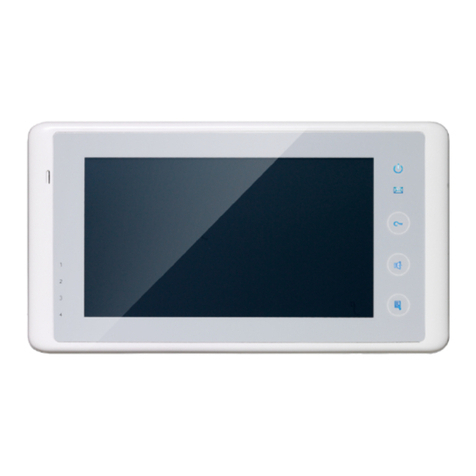
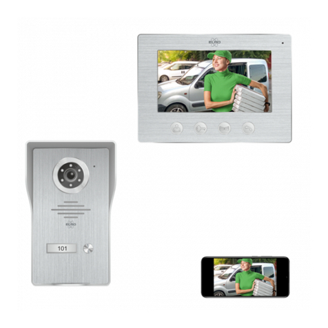
Elikon EVD2-30KIT User manual

ENGLISH
2-WIRE INTERCOM SYSTEM
USER MANUAL
TALK MENU MONITOR
EVD2-30KIT

1.Parts and Functions
2.Monitor Mounting
1. UsethescrewstofixtheMountingBracketonthemountingbox.(fittingaccesories
includesaBracket(Twopiecesof4X25screwsareneededforfasteningtheMounting
Bracket),Special2wirecablestoconnectwithMonitor)
2. Wirethesystemcorrectly(seethelaterconnectionchapter)thenhangtheMonitoron
theMountingBracketfirmly.
145~160 cm
Microphone
LCD Screen
LED Indicator
CALL Button
MONITOR Button
Direction Button
UNLOCK Button
TALK Button
MENU Button
Speaker
Mounting Hook
Connection Port
Extend Port
DIP Switches
1 2 3 4 5 6
ON
TALK MENU MONITOR
1

3. Basic Door Release Operation
4.Intercom Function
1. PressCALLbuttononoutdoorstation,theMonitor
rings,atthesametime,thescreendisplaysthe
visitorimage.
2. PressTALKButtononmonitor,youcan
communicatehandsfreewiththevisitorfor90
seconds.Afterfinishingcommunication,press
"TALK"buttonagaintoendthecommunication.
Ifnobodyanswersthephone,thescreenwillbe
turnedoffautomaticallyafter40seconds.
3. Duringtalkingstate,Press UNLOCKButtontoopenthedoorforthevisitor.
4. Whenthemonitorisinstandbymode,pressMONITORButton(orselectMonitor
itemonmainmenupage),Thescreenwillshowtheicon ▼
▼
▼
▼
,ifmultidoorstationsare
installed.press▲buttontochoosethefirstcamera,thescreenwilldisplaytheimagefrom
thefirstdoorcamera.Similarly,Press buttontochoosethesecondone,Press ▼button
tochoosethethirdone,Press buttontochoosethefourthone.Press"MONITOR"
buttonagaintoendmonitoring.
Whenthemonitorisinstandbymode,pressMENU
ButtontoenterIntercomFunctionpage.Use▲/▼
Buttontomoveupward/downwardtoselecttheitem
youwant,pressMENUButtontoenter.
Intercom Call >
Inner Call >
Call Guard Unit >
Intercom Call
[01] Mr A
[02] Mr B
[03] Mr C
[04] Mr D
Exit Dial
1. Intercom Call:Userinoneapartmentcancall
otherapartmentsinthesystem.thenamelistwill
becreatedautomaticallybythesystem.Seletea
nameonthescreenthenpressMENUButtonto
call.(Note:1.Press"MENU"buttonagaintoredial.
2.TheDIPswitchescodeofthemonitorsarenot
thesame.)
2

2. Inner Call:IfmultiMonitorsareinstalledinthesameapartment,selectInnerCall,
alltheotherMonitorswillringatthesametime,whicheverMonitoranswersthecall,
conversationisstarted.andtheothermonitorswillstopringingatthesametime.(note:the
DIPswitchessettingofallmonitorsmustbesame.)
3. Call Guard unit:AMonitorcanbeassignedasGuardUnitMonitor;whentheGuard
UnitMonitoranswersthecall,conversationwiththeguardpersonisstarted.
5.Monitor Function
Whenthemonitorisinstandbymode,pressMENU
Buttontoentermainmenupage.Use / Buttonto
moveleft/righttoselectthe item,thenuse▲/▼
Buttontomoveupward/downwardtoselecttheitem
youwant,pressMENUButtontoenter.
1. Monitor:Selectittomonitortheviewofoutside.
2. Monitor Doors:ifmultidoorstationsareinstalled,youcanpressMonitorDoors,and
thenpressthedoor1/2/3/4tomonitorthedoorstationorCCTVcamerayouwant.
3. Monitor Cameras:ifthesystemconnect2wirecameraviacameracontroller,youcan
pressMonitorCameras,andthenpressthecamera1/2/3/4tomonitorthecamerayou
want.
4. Monitor Time:Selectittosetmonitortime.
Monitor >
Monitor Doors >
Monitor Cameras >
Monitor Time >
6.Misc Function
Whenthemonitorisinstandbymode,pressMENU
Buttontoentermainmenupage.Use / Buttonto
moveleft/righttoselectthe item,thenuse▲/▼
Buttontomoveupward/downwardtoselecttheitem
youwant,pressMENUButtontoenter.
Playback >
Light >
Call Transfer >
3

1.Playback:Selectittoplaythevideos/picturesrecorded(orwhenthemonitorisinstandby
mode,pressCALLButtontoentertheplaybackfunction).
Note:theplaybackfunctionwillbeactivatedonlywhenthesystemconnectSC6Vmodule,
otherwise,thisfunctionisunvalidinnormal.Formoreinformation,pleaserefertoSC6V
userinstructionindetail.
2.light:Selectittoopenthestaircaselight(orpressstaircaselightbutton),thestaircaselight
willbeturnedoffautomatically.
Note:thestaircaselightfunctionwillbeactivatedonlywhenthesystemconnectlightvia
RT-SC6V/DT-RLCmodule,otherwise,thisfunctionisunvalidinnormal.Formore
information,pleaserefertoDT-SC6V/DT-RLCuserinstructionindetail.
3.Call Transfer:SelectitandpressMENUButtontoenterthetransfermode.Use▲/▼
Buttontomoveupward/downwardtoselecttheEditNumbersitemtoinputthetelephone
number,andthenuse▲/▼Buttontoincrease/decreasethevalue;use / Buttonto
selectlast/nextdigital.Afterinputing,pressMENUButtontoconfirm.
Playback >
Light >
Call Transfer >
Light Option
Turn on
Turn on 5 Min
Turn off
Exit
1:Don'tTransfer----callsfromoutdoorstationwillnotbediverted.
2:IfNoAnswer----outdoorstationcallsindoormonitorfirstly,ifnobodyanswer
thecallwithin30seconds,thecallwillbedivertedtothetelephonenumberyouset.
Atthismode,themonitorwillshutoffimmediatelywhenTPC/GSM/TPSdivert
sucessfully,whileitwon'taffectthecommunicationbetweenTPC/GSM/TPSand
outdoorstation.Otherwise,themonitorcandotheoperationofmonitoring,talking,and
unlocking.
3:Simutaneously----callsfromoutdoorstationwillbedivertedtoyourtelephone
immediately.Atthismode,themonitorwon'tshutoffwhenTPC/GSM/TPSdivert
sucessfully,butifthemonitoranswersthecallatthistime,TPC/GSM/TPSwillquit
absolutely.
Playback >
Light >
Call Transfer >
Call Transfer
Don’t Transfer
No Answer
Simultaneously
Edit Numbers
4

Restore to Default
SelectRestoreitemonusersetuppage,thenpressMENUbuttontoentertherestore
todefaultpage,andthenuse / Buttontomoveleft/righttoselectthe iconto
confirm.Allsettingswillberestoredtodefault.(Notethattherestoretodefaultoperation
willnotchangethetimesettingandthedatas.)
7.3 How to Enter User Setup Page
Select itemonmainmenupagetoentersetuppage,andthenuse ▲/ ▼Buttonto
moveupward/downwardtoselecttheUserSetupitem,thenpressMENUButtontoenter
theUserSetupmode.Youcanadjusttheringtune,ringvolumeandrestoreinthispage.
7.Basic Setup Instructions
7.1 How to Enter Main Menu Page
Intercom Call >
Inner Call >
Call Guard Unit >
PressMENUButtoninstandbymode,press
MENUButton,mainmenupagewillbeshowed.
Language >
User Setup >
About >
Exit
User Setup
Ring Tune
Ring Volume
Restore
Exit
User Setup
Ring Tune
Ring Volume
Restore
7.2 Language
SelectLanguageitemonsetuppage,thenpressMENUbuttontoenterthelanguagepage,
andthenuse ▲/▼Buttontomoveupward/downwardtoselectthelanguageyouwant.
(Thereare8languagescanbechosenforyou)
5

8. Monitor Parameter Setting
8.1 How to enter the installation setting page
Language >
User Setup >
About >
1.SelectAboutitemon
setuppage,pressMENU
Buttontoconfirm
2.PressUNLOCKbutton
andholdfor3s.
3.Use▲/▼Buttontoincrease/
decreasethevalue;useButton
toselectlast/nextdigital.After
inputing,pressMENUButtonto
confirm
Exit
About
H/W : a1.2
S/W : V01.01.01
Addr : 00.00
Video STD : AUTO
Exit
Installer Setup
[ 0000 ]
AMonitorcanbeassignedasGuardUnitMonitor;whentheGuardUnitMonitor
answersthecall,conversationwiththeguardpersonisstarted..
Thecodenumberof8004isusedtosetthemonitorasaguardunitmonitorand8005is
usedtocancelthisfunction.
8.2 How to set the monitor as a Guard Monitor
8.3 How to set the slave monitor address
Maximum4monitorscanbeconnectedinoneapartment,onemastermonitortogether
with3slavemonitors,soyoushouldsettheaddresscorrectly.(note:musthaveone
monitortobesetasmastermonitor)
Thecodeof8000isusedtosetthemastermonitor.
Thecodeof8001isusedtosetthefirstslavemonitor.
Thecodeof8002isusedtosetthesecondslavemonitor.
Thecodeof8003isusedtosetthethirdslavemonitor.
8.4 How to set the monitor panel on
Indefaultmode,whenreceiveacalling,themasterandslavemonitorswillringatthesame
time,andjustthemastermonitorcandisplaytheimagewhiletheslavemonitorscannot.
Butthesettingscanbechanged,youcansetthemastermonitorandalltheslavemonitors
topanelonatthesametimewhenreceivingacall,justinputthecodenumberof8006on
eachslavemonitor.
6

Theunlocktimecanbechangedbyyourselfatanytime.itcanbesetfrom1to9seconds.
Thecodenumberfrom8021to8029areusedtosettheunlocktimeto1~9seconds.
Unlock time:
8.5 How to set the unlock parameter
Therearetwounlockmodes:1.power-on-to-unlocktype:unlockmode=0(bydefault)
2.power-off-to-unlocktype:unlockmode=1.
Thecodenumberof8010isusedtosettheunlockmodeto0
Thecodenumberof8011isusedtosettheunlockmodeto1
Unlock mode:
Unlock menu:
Thecodeof8014isusedtoopentheunlockmenu.
Thecodeof8015isusedtoclosetheunlockmenu.
Note:
Whenyouinputcode8014toopentheunloskmenu,youcanreleasetwolocks.Atthis
mode,press UNLOCKbutton,twounlockiconswillbeshowed(Duringtalkingor
monitoringstate).Use / buttontoselecttheitemyouwant,andpressMENUbutton
toreleasethecorrespondingdoor.
DS-1 00:15
1.Duringtalkingormonitoring
state,press UNLOCKbutton.
DS-1 00:15
2.Use / buttontoselecttheitemyouwant,and
pressMENUbuttontoreleasethecorrespondingdoor.
TALK MENU MONITOR TALK MENU MONITOR TALK MENU MONITOR TALK MENU MONITOR
7

8.6 User Code Setup
•Bit 1 to Bit 5 are used to User Code setting. The value is from 1 to 32, which have 32
different codes for 32 apartments.
•When multi Monitors are installed in one apartment, these Monitors have to use the
same User Code setting, and the Master/Slave mode should be set on the Monitor.
•Bit 6 is line terminal switch, which have to be set to ON if the Monitor is in the end
of the line(bus), otherwise set to OFF. The end of the line is terminal that no other
ON(1)
=
OFF(0)
=
ON
ON
ON 123456
Bit state User Code Bit state User Code Bit state User Code
1 2 3 4 5 6
ON
Code=1
1 2 3 4 5 6
ON
Code=12
1 2 3 4 5 6
ON
Code=23
1 2 3 4 5 6
ON
Code=2
1 2 3 4 5 6
ON
Code=13
1 2 3 4 5 6
ON
Code=24
1 2 3 4 5 6
ON
Code=3
1 2 3 4 5 6
ON
Code=14
1 2 3 4 5 6
ON
Code=25
1 2 3 4 5 6
ON
Code=4
1 2 3 4 5 6
ON
Code=15
1 2 3 4 5 6
ON
Code=26
1 2 3 4 5 6
ON
Code=5
1 2 3 4 5 6
ON
Code=16
1 2 3 4 5 6
ON
Code=27
1 2 3 4 5 6
ON
Code=6
1 2 3 4 5 6
ON
Code=17
1 2 3 4 5 6
ON
Code=28
1 2 3 4 5 6
ON
Code=7
1 2 3 4 5 6
ON
Code=18
1 2 3 4 5 6
ON
Code=29
1 2 3 4 5 6
ON
Code=8
1 2 3 4 5 6
ON
Code=19
1 2 3 4 5 6
ON
Code=30
1 2 3 4 5 6
ON
Code=9
1 2 3 4 5 6
ON
Code=20
1 2 3 4 5 6
ON
Code=31
1 2 3 4 5 6
ON
Code=10
1 2 3 4 5 6
ON
Code=21
1 2 3 4 5 6
ON
Code=32
1 2 3 4 5 6
ON
Code=11
1 2 3 4 5 6
ON
Code=22
Bit 6 line terminal setting:
Bit state Setting Bit state Setting
1 2 3 4 5 6
ON
Monitor not at
the end of the
line.
1 2 3 4 5 6
ON
Monitor at
the end of
the line.
In the DT system,every apartment must have a unique identification called User Code.
The DIP swiches are used to configure the User Code for each Monitor.
section will start from it.
8

1. ThethirditemisScenemodeselection:Total4
screenmodescanbeselectedinsequence:
Normal,
User, Soft
and
Bright.
Wheneveryoumodify
Brightness
or
colour, Scene
itemwillbesetto
User
modeautomatically.
2. The
Brightness
and
Colour
itemisfortheimage
qualitysetting,adjustthevaluetogetthebestimage
youlike.
3. The
Ring Volume
and
Talk Volume
itemsareringtoneandtalkingvolumeadjustment.
4. Notethatallthemodificationswillbedoneimmediatelyaftertheoperation.Press /
buttontomoveleftmostorrightmostofmenutoquittheadjustpage.
10.Screen and Volume Adjustment
Duringmonitoringortalking,pressMENUButton,the
ADJUST MENU
willbedisplayed.
Use / Buttontoselecttheadjustmentitem;use▲/▼ Buttontodecrease/increase
thevalue,pressMENUButtontoconfirm.
DS-1 00:15
Brightness 5
9. Basic Connection
door
station
BUS(IM) BUS(DS)
PC6
AC~
Doorbell Button
Switch
1 2 3 4 5 6
ON DIP
TALK MENU MONITOR
9

11. Specications
●
●Power●supply●for●indoor●monitor:●● ● DC●20~28V●
●
●Power●consumption:● ●● Standby●7.51mA;●Working●status●155mA
●
●Monitor●screen:● ● 3.5●Inch●color●LCD
●
●Display●Resolutions:● ● 320(R,●G,●B)●x●240●pixels
●
●Video●signal:● ● 1Vp-p,●75Ω,●CCIR●standard
●
●Wiring:● ● 2●wires,●non-polarity
●
●Monitor●time:● ● 40●seconds
●
●Talking●time:● ● 90●seconds
●
●Dimensions:● ● 220(H)×105(W)×20(D)mm
10

Thedesignandspecificationscanbechangedwithoutnoticetotheuser.Righttointerpretand
copyrightofthismanualarepreserved.
TALK MENU MONITOR
Table of contents
Other Elikon Intercom System manuals


