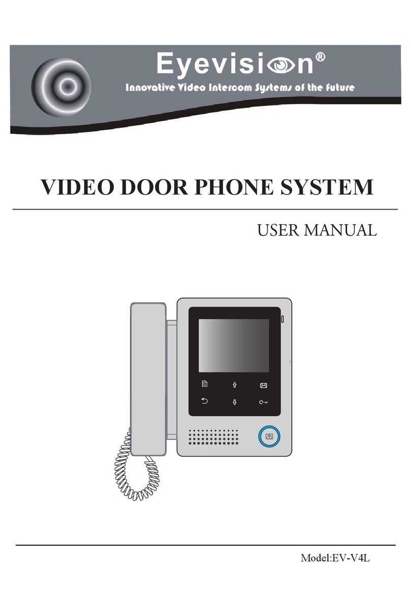
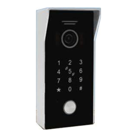
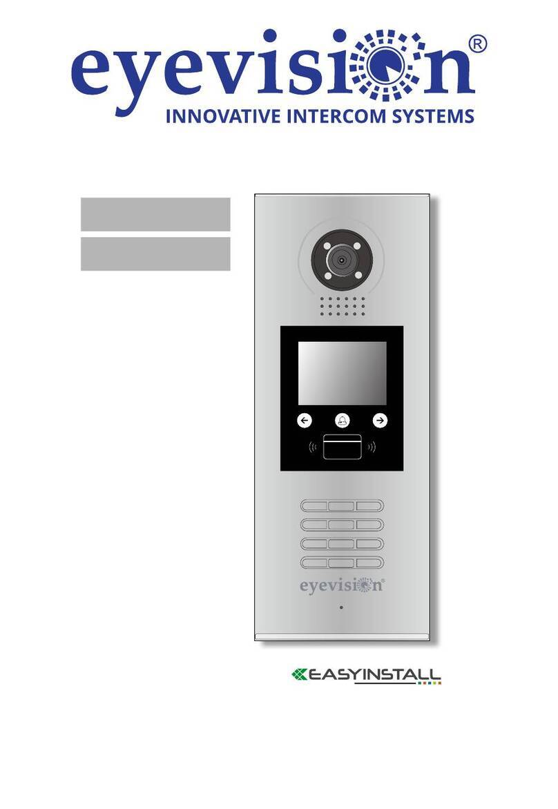
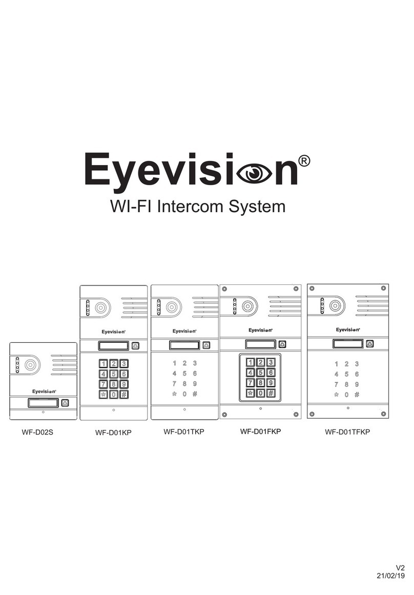
Eyevision EV-H298 User manual

V2.1
21/08/19
Eyevisi n
Eyevisi n
Eyevisi n
Hybrid 4 Wire Video Intercom System
with Net-link
EV-H7
EV-H298KP EV-H298FKP EV-H304KP EV-H304-4B
EV-H304FKP EV-H304F-4B
EV-H298
Eyevisi n
Net Link
Eyevisi n
Eyevisi nEyevisi n
Eyevisi nEyevisi n
Eyevisi nEyevisi n Eyevisi nEyevisi n
Eyevisi nEyevisi n

Table of Contents
Page 1
Installation Hints
Precautions
Page 2
Indoor Monitor and Netlink Overview
Jumper settings for Indoor Monitor and Netlink
Page 3
Outdoor station Installation Height
Power adapter and Power supply limitations
Page 4
EV-H298 (non keypad) outdoor station installation and wiring
Page 5
EV-H298KP outdoor station installation and wiring
Page 6
EV-H304 outdoor station installation and wiring
Page 7
EV-H304-4B Apartment outdoor station installation and wiring
Page 8
Apartment System Wiring Diagram
Page 9
Home System Wiring
One indoor to one outdoor unit (with/without netlink)
One indoor to two outdoor units with netlink
Two indoor to one unit with netlink
Page 10
Home System Wiring cont.
Two indoor to two outdoor units with netlink
Four indoor to two outdoor units without netlink
Page 11
Home System Wiring cont.
Four indoor to two outdoor units with netlink
Page 12
Operating the indoor monitor
Page 13
H298KP and H304KP Keypad Programming including unlock time setting
Page 14
H298 Unlock time setting
Setting the indoor monitor to Home/Apartment mode
Page 15
Controlcam2 Installation
Overview of Controlcam 2
Page 16
Preliminary setup of Netlink using an Android Device
Page 17
Preliminary setup of Netlink using an iOS device
Page 18
Changing the device and unlock password for controlcam 2
Setting the unlock time for controlcam 2
One key unlock via APP
Page 19
Adding a device already on the WiFi network to additional phones/tablets
Adding a device connected by ethernet cable
Troubleshooting

Due to our constant developments, your purchased model functions may vary slightly to the instruction manual provided.
We always endeavor to try to update our manuals regularly in accordance with the level of new development.
Connect this unit ONLY to other compatible units, Do not connect it to any other type of alarm or auxiliary device.
Connecting anything else to this unit may damage it or prevent it from operating correctly.
Do not place the power cords from the AC/DC adapters, camera or monitor where they can be pinched or cut.
Keep cords away from children’s, pets and routine household traffic.
Do not place heavy objects on power cords or cover cords with rugs or carpet.
When the system is not in use, please unplug the AC/DC adapters from the wall outlet.
Slots or openings in the back of the monitor are provided for ventilation and to ensure reliable operation of the video monitor or equipment and to protect it from overheating.
These openings must not be blocked or covered.
The monitor should never be placed near a heater and should not be placed in a built in installation such as a bookcase unless proper ventilation is provided.
All parts of the system should be protected from shocks and vibrations.
For cleaning the Lens & Screen please do the cleaning with a soft cotton cloth, do not use organic or chemical impregnate cloths. If necessary please use a damp soft cloth to clean
dust.
Image distortion may occur if the video door phone is mounted too close to magnetic field e. g. Microwaves, TV, computer etc.
Please keep the video door monitor away from wet areas, high temperature, dust, caustic and oxidation gas in order to avoid any unpredictable damage.
Every installation may vary slightly according to the user’s requirements. The recommended height for installing the monitor and the door station should be decided by the end user
based on their requirements.
The monitor’s height should be chosen according to the users height. A good rule to follow is that the center of the monitor screen should be around nose height.
The door station camera lens should also be around nose height.
1- Carefully choose and decide on a location to install the monitor, and then make a hole in the wall so the cable can come through the hole.
2- Fix the monitor’s bracket on the wall with screws please see mounting and installation.
3- Carefully choose and decide on a location to install the outdoor door station and then make a hole in the wall according to the door station’s instructions.
4- Lay the cable for connecting the monitor to the door station then feed the cable through.
5- Connect one end of the 4-core cable to the monitors; be sure to connect the correct colours. If you are not sure then purchase the ready made shielded cables with pre terminated
end plugs and simply plug in.
6- Plug in the power cable to the back of the monitor and into the back of the door station.
7- Slip the monitor onto the installed wall bracket.
8- Connect the other end of the cable to the door station and be sure to connect the correct colours the correct terminals or purchase the ready made cable.
9- Fix the door station on the wall.
10- Plug in the power supplies into a power point.
11- Allow 30 seconds for the power to settle.
12- Now the video intercom system can be used.
13- Please see operating instructions.
Precautions
Installation Hints
Page 1
CN 2 (2nd Outdoor station)
CN 1 (1st Outdoor station)
V(+12V)
GND (Negative)
J1 Jumper
J2 Jumper
EV-H7 Indoor Monitor
Front View Rear View
Page 2
Wiring and Distances for Intercom line
Net Link and WIFI Operational Distance
Yellow (Video)
Red (B+)
Black (GND) Black (GND) is also connected with the shield at each end of the system
Blue (Audio)
The operational distance of the Net Link WIFI system greatly depends on the router in use, walls in between the two systems and other factors such as
electrical interference. This can be judged quite easily by using your mobile phones WIFI indicator and ensuring you have STRONG signal Strength. The
average distance is around 20m+ but this will vary between installations and sites.
12V DC
RJ 45/CAT5/CAT6 Ethernet Cable
Door Station 1
Door Station 2
- Maximum of FOUR indoor monitors
- Maximum of TWO outdoor units
Recommended Cable Type:
4 Core Shielded .030mm up to 100m distance.
RG 59 Coaxial Cable with 1.5mm Pair up to 200m
Eyevisi n
System jumper settings
Remove the RING jumper (J1) from the NETLINK only to eliminate a dual ringing tone on the outdoor unit. There is no need to remove the ring jumper off any
of the indoor monitors.
If the video displayed on the phone/tablet is dark also remove the COAX jumper (J2) from the netlink.
If the video displayed on the indoor monitor is dark also remove the COAX jumper (J2) from the specific indoor monitor that the problem is occurring on.
If the video displayed on the indoor monitor is dark remove the COAX jumper (J2) from the specific indoor monitor that the problem is occurring on.
Systems with a NETLINK
Systems without a NETLINK
J1 Jumper
J2 Jumper
Rear Of Indoor Monitor Rear Of Netlink
Jumpers
Jumpers
Led Indicators:
Red LED: Power ON
Green LED Flashing: Outgoing Call
Green LED ON: Connected to Network
Green LED OFF: Not connected to the network
Important !
Note that the door station that is connected to INPUT 1 is the only
door station the can be manually monitored via the APP however
both door stations can be viewed with full communications when the
doorbell is pressed.

Outdoor Station installation height
Power Supply Limitations
Please install the door station at a height no less than 145cm to the center of the door stations
camera. Recommended height is between 145cm-160cm.
If the door station is mounted to low the camera may fail in seeing the guests face and will also
present issues for communication.
Page 3
DC
AC
+
-
OUT
OUT
Standard 12V Power Adapter
* Max distance is 3m
* Recommended cable to extend length is 14/020
pair
* Only one unit per power supply
12V DC 1.5A Power Supply
* Max distance is 10m
* Recommended cable to is 14/020 pair or greater
* Max two units per power supply

1
2
3
4
5
6
1
2
3
4
5
6
To Automatic Gate
Open/Close input
Electric Striker 12V 250mA Maximum
- Fail Secure Type/Power ON to unlock
Green
Green
Red
White
White (+12V)
(Black)
Negative
Automatic Gate System Connection
Electric Striker Connection (Fail Secure) Power on to unlock
Intercom Line 1. Blue (Audio)
Intercom Line 2. Black (GND)
Intercom Line 3. Red (B+)
Intercom Line 4. Yellow (Video)
Unlock Line 5. Green (Relay N/O)
Unlock Line 6. White (Relay COM)
Intercom Line 1. Blue (Audio)
Intercom Line 2. Black (GND)
Intercom Line 3. Red (B+)
Intercom Line 4. Yellow (Video)
Unlock Line 5. Green (Relay N/O)
Unlock Line 6. White (Relay COM)
H298 Front & Rear View
LED Light
Camera
Name Plate
Speaker
Call Button
Microphone
Screws
System
Wiring
Rain Cover
Screws Plastic wall plug
Rain Cover
H298 Installation into the rain cover
Intercom Connection
Unlock
connection
H298 Standard Outdoor Station
Page 4

CN 3
CN 3
CN 3
CN 2
CN 2
CN 2
1
2
3
4
5
1
2
3
4
5
1
2
3
4
5
1
2
3
4
1
2
3
4
1
2
3
4
CN 3
1. Exit Button (First Wire- N/O)
2. Exit Button (Second Wire-
COM)
3. Relay N/O
4. Relay Common
5. Relay N/C
CN 3
1. Exit Button (First Wire- N/O)
2. Exit Button (Second Wire-
COM)
3. Relay N/O
4. Relay Common
5. Relay N/C
CN 3
1. Exit Button (First Wire- N/O)
2. Exit Button (Second Wire-
COM)
3. Relay N/O
4. Relay Common
5. Relay N/C
+
-
+
-
+
-
To Automatic Gate
Open/Close input
Electric Striker 12V 250mA Maximum
- Fail Secure Type/Power ON to unlock
Electric Striker 12V 250mA Maximum
- Fail Safe Type/Power OFF to unlock
Green
Green
Blue
Blue
Blue (+12V)
Brown (+12V)
Negative
Negative
Automatic Gate Connection
Electric Striker Connection (Fail Secure) Power on to unlock
Electric Striker Connection (Fail Safe) Power off to unlock
Page 5
H298KP Front & Rear View
H298FKP Front & Rear View
LED Light
LED Light
Camera
Camera
Name Plate
Name Plate
Keypad
Keypad
Speaker
Speaker
Call Button
Call Button
Microphone
Microphone
Screws
System
Wiring
Rain Cover
Screws Plastic wall plug
Rain Cover
H298KP Installation into the rain cover
Screws
Screws
System
Wiring
Recess Box Plastic wall plug
H298FKP Installation into the rain cover
Eyevisi nEyevisi n
Intercom
Intercom
Exit Button
Exit Button
Power Supply
Power Supply
Connection
Connection
Connection
Connection
Unlock
Unlock
connection
connection
H298 Keypad Outdoor Station
Black/White
(+12V)
Black/White
(+12V)
Black/White
(+12V)
Black
(GND / -)
Black
(GND / -)
Black
(GND / -)
Standard
Power
Adapter
Standard
Power
Adapter
Standard
Power
Adapter

H304KP Front & Rear View
H304FKP Front & Rear View
LED Light
LED Light
Camera
Camera
Keypad
Keypad
Speaker
Speaker
Call Button
Call Button
Microphone
Microphone
Screw
System
Wiring
Rain Cover
Screws Plastic wall plug
Rain Cover
H304KP Installation into the rain cover
Screws
Screws
System
Wiring
Recess Box Plastic wall plug
H304FKP Installation into the rain cover
Intercom
Intercom
Power Supply
Power Supply
Connection
Connection
Connection
Connection
Unlock
Unlock
connection
connection
Eyevisi nEyevisi n
Eyevisi nEyevisi n
Eyevisi nEyevisi n
Eyevisi nEyevisi n
H304 Keypad Outdoor Station
Black/White
(+12V)
Black/White
(+12V)
Black/White
(+12V)
Black
(GND / -)
Black
(GND / -)
Black
(GND / -)
Standard
Power
Adapter
Standard
Power
Adapter
Standard
Power
Adapter
1
2
3
1
2
3
1
2
3
1
2
3
4
1
2
3
4
1
2
3
4
CN 3
1. +12V
2. Negative/GND
CN 2
1. NO Exit Button
2. Button Common
CN 4
3. Relay N/C
4. Relay Common
5. Relay N/O
CN 3
1. Exit Button (First Wire- N/O)
2. Exit Button (Second Wire-
COM)
3. Relay N/O
4. Relay Common
5. Relay N/C
CN 3
1. Exit Button (First Wire- N/O)
2. Exit Button (Second Wire-
COM)
3. Relay N/O
4. Relay Common
5. Relay N/C
+
-
+
-
+
-
To Automatic Gate
Open/Close input
Electric Striker 12V 250mA Maximum
- Fail Secure Type/Power ON to unlock
Electric Striker 12V 250mA Maximum
- Fail Safe Type/Power OFF to unlock
COM
COM
(COM)
NO
(NO)
NC
+12V
+12V
Negative
Negative
Automatic Gate Connection
Electric Striker Connection (Fail Secure) Power on to unlock
Electric Striker Connection (Fail Safe) Power off to unlock
Page 6
B
T
N
B
T
N
B
T
N

To Automatic Gate
Open/Close input
Electric Striker
Electric Striker
Automatic Gate System Connection
Electric Striker Connection (Fail Secure) Power on to unlock
Electric Striker Connection (Fail Safe) Power off to unlock
Intercom Monitor Lines (CN 1 to CN 4)
Yellow (Video)
Red (B+)
Black (GND)
Blue (Audio)
CN6
Blue (NC)
Black (Com)
Red (NO)
Intercom Monitor Lines (CN 1 to CN 4)
Yellow (Video)
Red (B+)
Black (GND)
Blue (Audio)
CN6
Blue (NC)
Black (Com)
Red (NO)
Intercom Monitor Lines (CN 1 to CN 4)
Yellow (Video)
Red (B+)
Black (GND)
Blue (Audio)
CN6
Blue (NC)
Black (Com)
Red (NO)
H304-4B Front & Rear View
H304F-4B Front & Rear View
LED Light
LED Light
Camera
Camera
Speaker
Speaker
Call Buttons
Call Buttons
Microphone
Microphone
Screw
System
Wiring
Rain Cover
Screws Plastic wall plug
Rain Cover
H304-4B Installation into the rain cover
Screws
Screws
System
Wiring
Recess Box Plastic wall plug
H304F-4B Installation into the rain cover
Intercom
Intercom
Exit Button
Exit Button
Power Supply
Power Supply
Connection
Connection
Connection
Connection
Unlock
Unlock
connection
connection
Eyevisi nEyevisi n
Eyevisi nEyevisi n
Eyevisi nEyevisi n
Eyevisi nEyevisi n
H304-4B Apartment Outdoor Station
Standard
Power
Adapter
Standard
Power
Adapter
Standard
Power
Adapter
Black
(-)
Black
(-)
Black
(-)
Black/White
(+)
Black/White
(+)
Black/White
(+)
+
+
-
-
Page 7

12V
Adapter
12V
Adapter
12V
Adapter
12V
Adapter
12V
Adapter
12V
Adapter
2C
2C
2C
2C 2C
2C
CN 1
CN 1
CN 1
CN 1
CN 1
Input
on
each monitor
CN 2
Input
on
each monitor
CN 1
CN 1
12V
Adapter
2C
Netlink
CN 1
CN 3 CN 2
12V
Adapter
12V
Adapter
12V
Adapter
Door Striker
or Auto Gate
Door Striker
or Auto Gate
Door Striker
or Auto Gate
2C
2C 2C
2C
2C
2C
Apartment 1
12V
Adapter
2C
Apartment 1
Apartment 2
12V
Adapter
2C
Apartment 2
Apartment 3
12V
Adapter
2C
Apartment 3
Apartment 4
12V
Adapter 2C
Apartment 4
Additional monitor
Apartment 4
for apartment 2
Additional monitor
Apartment 4
System Expansion
System Expansion
Netlink Expansion
Each apartment that has its own internet
connection can have its own netlink
installed so that they can receive calls on
iOS and Android devices. The 4 wire
connection is performed directly off that
apartments intercom line in parallel with
the indoor monitor.
Note: Only apartments requiring this
feature require a netlink.
Monitor Expansion
Each apartment requiring additional
monitor(s) has the ability to do so with an
expandability of up to FOUR monitors per
apartment . The 4 wire connection is
performed directly off that apartments
intercom line in parallel with the first indoor
monitor.
12V
Adapter
2C
Netlink
CN 1
CN 3 CN 2
Netlink Expansion
Each apartment that has its own internet
connection can have its own netlink installed so
that they can receive calls on iOS and Android
devices. The 4 wire connection is performed
directly off that apartments intercom line in
parallel with the indoor monitor.
Note: Only apartments requiring this feature
require a netlink.
Monitor Expansion
Each apartment requiring additional monitor(s)
has the ability to do so with an expandability of
up to FOUR monitors per apartment . The 4 wire
connection is performed directly off that
apartments intercom line in parallel with the first
indoor monitor.
Wiring Layout One Outdoor Station
Wiring Layout Two Outdoor Station
Apartment System Wiring
for apartment 4
Page 8

12V
Adapter
12V
Adapter
2C2C
CN 1CN 1 CN 2CN 2
12V
Adapter
12V
Adapter
2C2C
NetlinkNetlink
CN 1CN 1
CN 3CN 3 CN 2CN 2
12V
Adapter
12V
Adapter
12V
Adapter
12V
Adapter
Door Striker
or Auto Gate
Door Striker
or Auto Gate
Door Striker
or Auto Gate
Door Striker
or Auto Gate
Keypad Door
Stations Only
Keypad Door
Stations Only
Keypad Door
Stations Only
Keypad Door
Stations Only
2C2C
2C2C
2C2C 2C2C
12V
Adapter
12V
Adapter
12V
Adapter
12V
Adapter
2C2C
2C2C
CN 1 CN 1
12V
Adapter
12V
Adapter
2C2C
NetlinkNetlink
CN 1CN 1
CN 3CN 3 CN 2CN 2
12V
Adapter
12V
Adapter
Door Striker
or Auto Gate
Door Striker
or Auto Gate
Keypad Door
Stations Only
Keypad Door
Stations Only
2C2C
2C2C
12V
Adapter
12V
Adapter
2C
2C
CN 1
CN 1
12V
Adapter
2C
Netlink
CN 1
CN 3 CN 2
12V
Adapter
12V
Adapter
Door Striker
or Auto Gate
Door Striker
or Auto Gate
Keypad Door
Stations Only
Keypad Door
Stations Only
2C
2C
2C
2C
Wiring Layout One Outdoor Station and One Monitor (With Netlink)
Wiring Layout One Outdoor Station and One Monitor (Without Netlink)
Wiring Layout Two Outdoor
Station and One Monitor
Wiring Layout One Outdoor
Station and Two Monitors
Home System Wiring
Page 9

12V
Adapter
12V
Adapter
12V
Adapter 12V
Adapter
12V
Adapter
12V
Adapter
Door Striker
or Auto Gate
Door Striker
or Auto Gate
2C
2C
2C
2C 2C
2C
2C
2C
CN 1 CN 1
CN 1 CN 1
CN 2 CN 2
CN 2 CN 2
Keypad Door
Stations Only
Keypad Door
Stations Only
Wiring Layout Two Outdoor Station and Four Monitors (Without Netlink)
12V
Adapter
12V
Adapter
12V
Adapter
12V
Adapter
2C2C
2C2C
CN 1CN 1 CN 1CN 1 CN 1CN 1
CN 2CN 2 CN 2CN 2
12V
Adapter
12V
Adapter
2C2C
NetlinkNetlink
CN 1CN 1
CN 3CN 3 CN 2CN 2
12V
Adapter
12V
Adapter
12V
Adapter
12V
Adapter
Door Striker
or Auto Gate
Door Striker
or Auto Gate
Door Striker
or Auto Gate
Door Striker
or Auto Gate
Keypad Door
Stations Only
Keypad Door
Stations Only
Keypad Door
Stations Only
Keypad Door
Stations Only
2C2C
2C2C
2C2C 2C2C
Wiring Layout Two Outdoor Station and Two Monitors (With Netlink)
Home System Wiring continued
Page 10

12V
Adapter
12V
Adapter
12V
Adapter 12V
Adapter
2C
2C
2C
2C
CN 1 CN 1
CN 1 CN 1
CN 2 CN 2
CN 2 CN 2
12V
Adapter
2C
Netlink
CN 1
CN 3 CN 2
12V
Adapter
12V
Adapter
Door Striker
or Auto Gate
Door Striker
or Auto Gate
Keypad Door
Stations Only
Keypad Door
Stations Only
2C
2C
2C 2C
Wiring Layout Two Outdoor Station and Four Monitors (With Netlink)
Home System Wiring continued
Page 11

Answering Visitor Calls
Monitoring
Transferring the Call
Page 12

1. Information
*The factory default programming password
is *1234, this is NOT the PIN number.
*In the programming mode you can set up to 40 groups of 4-digit PIN numbers to unlock.
* 30 Groups have adjustable unlock time and 10 are fixed on a momentary pulse.
2. Modify the programming password
1) Switch off the power then press and hold the * button, switch on the power. After a continuous alarm is heard then release the button.
2) The continuous alarm will now stop. Now enter a new 4 digit programming password.
3) Another long Di sound will be heard, it indicates modifying is successful.
3) Press * to exit the programming mode.
3. Enter the programming mode
From standby press * a Di sound will be heard now enter the 4 digit programming password (Default is *1234).
A long Di sound will be heard to indicate that the keypad has entered programming successfully.
The keypad will timeout of the programming mode after 30 seconds of idle state or you can press * to exit to standby.
4. Setting the unlock time
Factory default unlock time is 1 second.
1) Enter the programming mode (Default is *1234) .
2) Press 00 then a long Di sound will be heard,
3) Enter the unlock time in seconds (from 01-99) then another long Di sound can be heard. This indicates setting successfully.
3) Press * to exit the programming mode.
5. Add user PIN codes
1) Enter the programming mode (Default is *1234) .
2) Enter a 2 digit user number from 01-40 a long Di sound will be heard.
3) Press 4 digits (can be 2-6 digits) password then another long Di sound will be heard this indicates adding was successful.
4) Press * to exit the programming mode.
Position 01-30 are for a latching time or a momentary pulse.NOTE:
Position 31-40 are for a momentary pulse only.
6. Delete user PIN codes by user number
1) Enter the programming mode (Default is *1234).
2) Enter the 2 digit user number (from 01-40) a long Di sound will be heard
3) Press * to confirm, another long Di sound can be heard this indicates the deleting is successful.
3) Press * to exit the programming mode
.7. Delete user PIN codes by PIN
1) Enter the programming mode (Default is *1234).
2) Press # then you will hear a DiDi sound enter the PIN you wish to delete, a long Di sound can be heard to indicate a successful delete.
3) Press * to exit the programming mode.
8. Factory Default Settings (Partial)
1). Enter the programming mode (Default is *1234).
2). Press #, when a DiDi sound is heard, press # again a long Di
Sound can be heard
3) Press # for 7 times after 3 seconds another long Di sound will be heard it indicates deleting successful.
4) Press * to exit the programming mode.
- Unlock time will be restored to 1 second.
- User PIN numbers will be deleted
- Programming password and digit length will remain the same.
9. Factory Default Settings (button type keypad) (Full)
1) Switch off the power then press and hold #.
2) Whilst holding # switch on the power.
3) A continuous alarm will be heard, now release # and after 3 seconds a long Di sound will be heard.
- Unlock time will be restored to 1 second.
- User PIN numbers will be deleted
- Programming password will revert to 1234
- Password and PIN number length will return to the 4 digit default.
10. Factory Default Settings (touch type keypad) (Full)
1) Switch off the power.
2) Switch on the power.
3) Hold down the # key within 2 seconds of powering on.
4) A continuous alarm will be heard, now release # and after 3 seconds a long Di sound will be heard.
- Unlock time will be restored to 1 second.
- User PIN numbers will be deleted
- Programming password will revert to 1234
- Password and PIN number length will return to the 4 digit default.
Page 13
Keypad Setup Guide

Setting the unlock time for H298 (Non Keypad) and H304 Apartment outdoor station
Setting the system to apartment mode (Disable intercom call feature)
Setting the system to home mode (Enable intercom call feature)
This procedure is performed from the standby state and will need to be set on all monitors in the
installation.
The default setting is one second (pulse).
1. Press and hold the talk key on the monitor til a ding dong is heard.
2. Press the unlock key the number of times you would like to set the unlock time too.
example: 5 presses would equal 5 second or 10 presses would equal 10 seconds.
3. Press the talk key once to confirm and save the new setting
This procedure is performed from the standby state and will need to be set on all monitors in the
installation.
The default setting is intercom enabled (home mode) which is not suitable for apartments.
Press and hold the unlock key on the monitor til a long beep is heard this confirms the unit is in
apartment mode.
After completing this procedure on all indoor monitors wait for 30 seconds after final monitor is
completed the turn off the power to the system and then back on to restart.
This is the default setting of any monitor and does not require adjustment for a home system.
This procedure is performed from the standby state and will need to be set on all monitors in the
installation.
The default setting is intercom enabled (home mode) which is not suitable for apartments.
Press and hold the unlock key on the monitor til a Di Di is heard this confirms the unit is in home
mode.
After completing this procedure on all indoor monitors wait for 30 seconds after final monitor is
completed the turn off the power to the system and then back on to restart.
Page 14

Android users can download ControlCam 2 App from Google Play while iOS users can download it from iOS App Store.
Complete the installation on your smart phone(or tablet) before proceeding.
Net Link Setup Guide
Page 15
1
2
3
4
5
6
7
8
9
Capture an image
Start a video recording
Enable/Disable the sound from the guest
Enable/Disable Mute
Full Screen
Unlock Button
Notifications
Exit
Push to talk
1
2
6
6
43
5
7
8
Setup and Log in with a New User Account
Using the App
1. Ensure your smart device is connected to your local Wi-Fi network (and on the internet). This network must be a 2.4GHZ network.
2. Open the ControlCam2 app.
3. Click the button.Sign Up
4. Enter a new user name.
5. Enter a new password.
6. Confirm your new password.
7. Select to confirm you have read the terms and conditions.
8. Press the Submit button and a registration success message will appear.
9. You will then see the login screen.
10. Press the Login button to log into the app.
IMPORTANT NOTES:
• You can concurrently connect iOS and Android devices to the same Outdoor station unit.
• You can add an unlimited number of the Outdoor station to your app.
• Each Outdoor station will support up to 4 concurrent connections.
• Each connection should use a unique account - you cannot connect from different smart devices with the same
user name and password.
Accepting or Declining Calls:
1. When the ring notification appears, click the green icon to accept the call and
to talk to the visitor. To decline the call, press the red icon.
2. To speak to the visitor, press and hold the microphone icon.
3. To listen to the visitor, release the microphone icon.
4. To exit the door station communication you must press the icon.

Page 16
Android Device Preliminary Setup
NOTE: This is the absolute FIRST step which is critical and must be
performed to allow the unit to be configured to your settings
Press and hold the “RESET” button on the backside of the Net Link
for 5 seconds WHILST the unit is powered ON and release
the button after hearing the beep.
Reset Button
7. Enter the WiFi password correctly and accurately.
Note: If the password is entered incorrectly it will present a connection issue and
the process must be performed again including the initial hard reset.
eyevision
********
6. Then the name of your local Wi-Fi network should then appear as shown, If not select from
the drop down list.
Note: The network must be a 2.4ghz connection.
eyevision
eyevision
LIDAWxxxxx
1. After performing the preliminary hard reset (see above)
GOTO the WiFi settings on your phone/tablet and connect to the network named
“LIDAW.....” ,you will be prompted there is no internet connection available on
this network which is correct.
2. Enter the ControlCam2 APP 3. Press the “+” button to add a device
5. Press the button.Hotspot Connection
On the following screen press .Next
4. Choose the Doorbell 1/Type 1 option.
Do not change the GID number
Username is admin
Password is 1234
Name is the display name within the
APP such as “Home”
8. Then you will see the below details screen,
enter the default password (1234)
and the name of the device.
Then press . Save
.
9. Wait for approx 1 minute for the device to complete its automatic restart and
connect to the WiFi network.
10. Press the thumbnail image to view live video.
NOTE:
once the outdoor station is added to the app you will be able to connect to it over the internet either via Wi-Fi or mobile(3G/4G) data.

iOS Device Preliminary Setup
NOTE: This is the absolute FIRST step which is critical and must be
performed to allow the unit to be configured to your settings
Press and hold the “RESET” button on the backside of the Net Link
for 5 seconds WHILST the unit is powered ON and release
the button after hearing the beep.
Reset Button
7. Minimize the controlcam2 APP and GOTO the WiFi settings on your
phone/tablet and connect to the network named“LIDAW.....”
6. Then the name of your local Wi-Fi network should then appear as shown.
Do not enter the password yet.
eyevision
1. After performing the preliminary hard reset (see above)
ensure your device is connected to the home WiFi network.
2. Enter the ControlCam2 APP 3. Press the “+” button to add a device
5. Press the button.Hotspot Connection
On the following screen press .Next
4. Choose the Doorbell 1/Type 1 option.
Do not change the GID number
Username is admin
Password is 1234
Name is the display name within the
APP such as “Home”
8. Then you will see the below details screen,
enter the default password (1234)
and the name of the device.
Then press . Save
.
9. Wait for approx 1 minute for the device to complete its automatic restart and
connect to the WiFi network.
10. Press the thumbnail image to view live video.
NOTE:
once the outdoor station is added to the app you will be able to connect to it over the internet either via Wi-Fi or mobile(3G/4G) data.
eyevision
7. Return to the controlcam2 APP, enter the WiFi password correctly and accurately then
press . Next
Note: If the password is entered incorrectly it will present a connection issue and
the process must be performed again including the initial hard reset.
eyevision
********
Page 17

2. Set the Unlock Time
The unlock time is configurable from 1 to 100 seconds. The Outdoor station’s unlock time by default, is set to 1 second.
1. 1. From the home screen within the APP press the icon.
2. Locate the unlock time setting then touch the current time.
3. Enter a new door unlock time of between 2 and 100 seconds.
4. Press .OK
5. Press Save.
NOTE:
The unlock time is user/app-specific. Therefore if you have multiple users connections to the same outdoor station then each
device can have its own unlock time. (example: client #1 can use an unlock time of 5 seconds and a second client can
use an unlock time of 10 seconds).
3. Enable One-Key Unlock
The One-Key Unlock feature gives you the slightly less-secure option of unlocking the door immediately following a single press of the
unlock icon. By default you are required to enter an unlock password (default is 1234).
1. From the home screen within the APP press the icon.
2. Locate the One-Key Unlock option and press the highlighted icon to enable it. The icon will turn green.
3. Enter the unlock password (default is 1234).
4. Press .Save
1. Change Device and Unlock Password
The default password for the outdoor station is 1234 so you should change the default password as soon
as possible (after adding the outdoor station to your app).
1. From the home screen within the APP press the icon.
2. Press .Advanced Settings
3. Select .Modify Device Password
4. Enter the existing password (default is 1234).
5. Enter a new password.
6. Confirm entry of the new password.
7. Press .Save
NOTE:
If the device password is changed this will effect other clients connected to that same device, you will need to change the
password in the settings of there device.
1. In the other devices app press the icon on the home screen.
2. Enter the new password in the field you see highlighted below:
3. Thenpress Save
Configuring the Netlink via Controlcam 2
Page 18
This manual suits for next models
7
Table of contents
Other Eyevision Intercom System manuals

Eyevision
Eyevision EV-IP-KP22 User manual

Eyevision
Eyevision EV-D298F Series User manual

Eyevision
Eyevision WF-D02S User manual

Eyevision
Eyevision EV-V4L User manual

Eyevision
Eyevision EV-DMR18S User manual

Eyevision
Eyevision Intelli Series User manual

Eyevision
Eyevision EV-D301 User manual

Eyevision
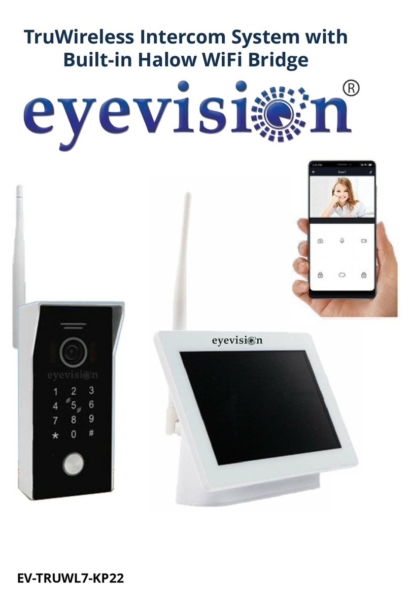
Eyevision EV-TRUWL7-KP22 User manual
Popular Intercom System manuals by other brands

Bticino
Bticino Axolute 349311 user manual

Videx
Videx CVR4KV owner's manual

Trigon Electronics
Trigon Electronics MiniGuard IID Programming guide

Federal Signal Corporation
Federal Signal Corporation E1 Nstallation and service instructions

NETPHONE
NETPHONE BT INTERPHONE V8 user manual

Aristel
Aristel AN1603-01 operating manual