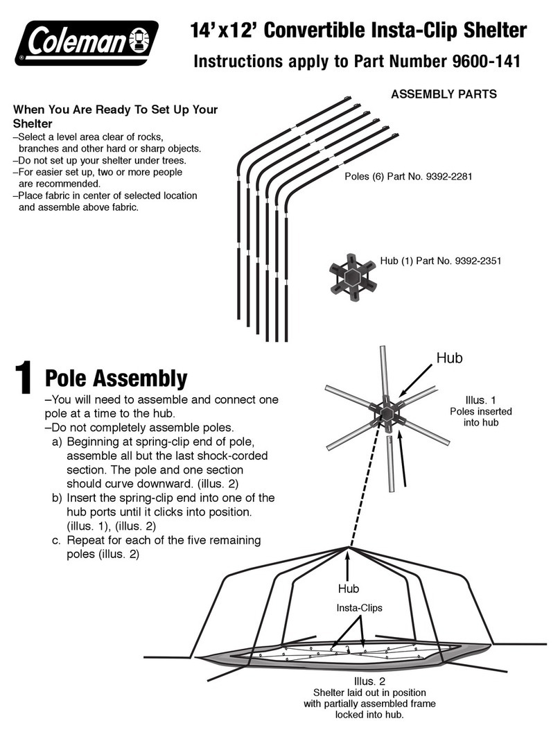
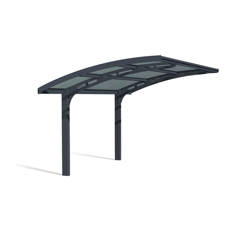
Elite Greenhouses KENSINGTON 6 x 6 User manual


6 X 6 8 X 6 10 X 6 12 X 6
1 50’Glazing beading 1 1 0 0
2 100’Glazing beading 2 2 3 3
3 Eave gusset plate 2 2 2 2
4 Black draught excluder 2 2 2 2
5 Top door panel Taped together and
marked door 1 1 1 1
6 Bottom door panel 1 1 1 1
7 Door infill panels 3 3 3 3
8 Door track support 1 1 1 1
9 Ridge Taped together in
extension box 1 1 1 1
10 Gutter / Eave 1 1 1 1
11 Front Cill 1 1 1 1
12 Heavy angle brace 1 1 1 1
13 Rear end cill Taped together and
marked end 1 1 1 1
14 Rear end glazing bar 2 2 2 2
15 Rear end horizontal bracing angle 1 1 1 1
16 Rear end wall bar 1 1 1 1
17 Door end cill Taped together and
marked en 1 1 1 1
18 Door end glazing bar 2 2 2 2
19 Door end horizontal bracing angle 1 1 1 1
20 Door end wall bar 1 1 1 1
21 Door glazing bars—marked door 2 2 2 2
22 Front glazing bars—marked front 2 3 4 5
23 Corner bars—taped in two packs
1 = left end, 1 = right end 4 4 4 4
24 Short bracing angles marked door end 3 3 3 3
25 6’shelf 1 1 1 1
26 Vent (in packs) 1 1 1 1
27 Louvre (in packs) 1 1 1 1
28 Door track 1 1 1 1
29 Roof glazing bars Taped
together and marked
roof
2 3 4 5
30 Roof strengthening bars 2 3 4 5
31 Roof flat bars 3 4 5 6
32 The following items can be found in the bag of fittings or additional packages.
Skeleton gun, tube of silicon, rolls of foam seal, anchor brackets, stainless steel screws, plastic plugs, M10
nuts and bolts, stainless steel clips, wire clips, overlap clips, casement stays, stay pins, M4 pins, nuts and
bolts, door catch, short and long self tapping screws, spring washers, door skids, door wheels and fittings.
PARTS LIST

Glass
For both toughened glass and horticultural glass, please refer to the relevant glass plans towards the
rear of this booklet.
* If your building is longer than 6’5’’, the extra bar for the roof and front are in the longer box
which contains the gutter, ridge and cills e.g. a 10 x 6 would have an extra 2 front bars, roof bars,
angles and flat bars in the longer box
.
HELPFUL HINTS
Please do take your time during construction and follow the safety code.
·
Read all instructions carefully.
·
Ensure that your base is level and square and built to the precise measurements indicated on
the base section of this booklet.
·
Base must be 90º to the wall it leans against.
·
Do not alter the dimensions or shape of any component unless indicated to do so.
·
This plan covers the entire range of 6’wide lean-to models and their options including door
positions (front, gable end or double front), louvre location, shelf construction and vent
construction.
·
It is therefore possible that you may have remaining components on the completion of
construction. The reason for this would be because one option has been chosen in preference
to another.
·
This detailed assembly instruction booklet will explain the construction procedures you
require to correctly install your particular structure.
·
For the purpose of coloured models:
1. There may be some jig holes in some bars, these holes play no part in the
assembly but assist in the painting process.
2. Extra care must be taken in assembly of all coloured models so as not to scratch the
paint and hence affect the appearance of the structure.
SAFETY
·
When using electrical equipment outside always use a circuit breaker.
·
Do not attempt to construct frame or glazing of lean-to in high winds.
·
Glass is fragile, so safety gloves and eye protection should be worn when glazing any part
of the structure.
·
Please remember that if lean-to is to be situated over an entrance to a house or dwelling,
4mm safety glass must be used to eave level. Horticultural glass is unacceptable in this
situation.
·
Do not place structure in vulnerable situation. Children should not play near glass
greenhouses.
·
Failure to observe these rules could result in personal injury or property damage.
BEWARE
M10 Spanner Masonry bit
Heavy duty flat screwdriver Hacksaw
Pair of pliers Sharp cutting tool
Electric drill/circuit breaker Metal file
REQUIRED TOOLS

CONSTRUCTION OF FRAMEWORK AND WORK
PROCEDURE
The structure should be completed from start to finish in the following order
1. Base preparation
2. Construction of frame assemblies
3. Joining of sub-assemblies to make full size frame
4. Securing structure to the base and wall
5. Glazing
6. Finishing off
Each of the above procedures are detailed at the appropriate stages of this booklet.
BASE SIZE AND PREPARATION
(for brick/concrete bases only)
Kensington
6’model Length
(Dimension B) Width
(Dimension A) √
Square External ridge
height
6 x 6 model 1.960m 1.915m 2.7402m 2.387m
8 x 6 model 2.578m 1.915m 3.2114m 2.387m
10 x 6 model 3.196m 1.915m 3.7258m 2.387m
12 x 6 model 3.814m 1.915m 4.2678m 2.387m
14 x 6 model 4.432m 1.915m 4.828m 2.387m
16 x 6 model 5.050m 1.915m 5.401m 2.387m
18 x 6 model 5.668m 1.915m 5.983m 2.387m
20 x 6 model 6.286m 1.915m 6.571m 2.387m
CONSTRUCTION OF THE FRAMEWORK ASSEMBLIES
The building is divided into a number of different frame assemblies.
1. Right hand gable end frame
2. Shelf installation
3. Left hand gable end frame
4. Front frame assembly
5. Roof frame assembly
6. Double door assembly
7. Roof vent assembly
8. General assembly of greenhouse unit.
9. Construction and installation of louvre
NB. If you have a corner location, i.e. one end missing (R-type)–all base lengths reduced by
40mm.
All bases of any material must be level and square and built to exact outside measurements.

The installation procedure should follow the above format and it is recommended that you complete
each one fully before moving onto the next frame.
For the purpose of this booklet, we have used an 8 x 6 lean–to as the basis for construction. If you
have purchased another size, the principles of the job are identical.
All bases, of any material must be level and square and built of the exact outside
measurements
If you are putting a concrete footing down it is wise to dig a trench around the perimeter removing
all top soil, insert some hard-core (broken brick etc) into the trench and back fill with concrete.
You can now begin to lay the required course of brick, remembering to insert a damp-proof strip
one or two courses above ground level.
ELITE GREENHOUSES BASE DIMENSIONS
For brick, Block, Concrete or Timber
The dimensions given on the previous page must be used to locate the position of your lean-to
greenhouse brick base.
If a brick, concrete or timber base is to be laid, construct it as shown ensuring that dimensions A &
B are not exceeded as these are the precise outside measurements enabling the cill to overhang the
edges.
ENSURE that the base is square by measuring across the corners, only when equal is it square.
Check the level using a builders spirit level.
If you have a patio floor you can lay the bricks directly on top of the flags provided they have a
proper foundation. If you don’t have hard standing underneath you may need to lift the outer flags
and insert some firmer material such as aggregate before laying the bricks.
Please proceed along the following format.
Before commencing the detailed frame assemblies, you must decide which gable is going to be the
door end, and which is to be fixed end. (Key point). For the purposes of this plan, we have made
the left hand gable the door end, but it can just as easily be the right hand end, so please read the
instructions with the alternative in mind (Key point).

If you have bought an alloy base to go with the house, start with this
1. Lay the three base sections on level ground in a rectangle with the bolt channels facing inward
and the flanges facing outwards, remembering to put the wider of the two flanges towards
the floor. (Key point).
2. Slide a bolt into each end of the bolt channels in each section (i.e four bolts to each).
IMPORTANT: If you plan to erect the greenhouse on a patio or flagged area, you need
to insert some extra bolts in the lower channels. See 13 below.
3. Attach an angle stake to the first corner by pushing the bolts through the holes in the stake and
securing with a nut. You do not need to fasten them tightly at this stage.
4. Repeat this with the other corner.
5. Ensure that the frame is square by measuring from corner to corner. Only when the diagonals
are equal is the frame square. Tighten all the nuts (Key point).
6. Get someone to help you carry the base frame to place where you want the greenhouse to be
situated.
7. a) If you are erecting on soil, mark where the corners will be and follow points 8 to 10
below.
b) If you are putting on a patio or flagged area, jump to point 11*
8. Lift the base frame clear of the site and dig a hole at each corner, sufficient in depth to take
the angle stakes.
9. Re-position the base in the desired position, ensure that it is still square by checking the
diagonals again and then that it is level using a spirit level. When you are sure that both are
correct give the nuts a final tightening
10. Skip the next points and go to greenhouse assembly
N.B. It is advisable to concrete the corner stakes after you have erected the greenhouse. If
you do it before and are slightly out of square you cannot make any adjustments (Key point).
11. You must ensure that your patio is level. If it is not, you must level it up first or the green
house will not be level and will not glaze properly.
12. Cut off the surplus portions of the angle stakes, and then cut them into two inch sections.
Drill a quarter inch hole in each side of each one. The holes must be drilled so that when
placed on the flagged area channel of each side and end, as mentioned in point 2 above.
13. These surplus pieces are going to be used to anchor the base to the flagged area. You should
have enough for four pieces to each side. These are the number of extra bolts you need to
insert into the bottom channel of each side and end, as mentioned in point 2 above.
14. Check that the base is still square by measuring the diagonals again, and level by using a spirit
level.
15. Space the bolts in the sides and ends at equal distance and place the brackets on them,
securing them with a nut.
16. Do not anchor down at this stage (Key point)
BEWARE OF SHARP EDGES
ON THE CORNERS
DO NOT OVER TIGHTEN NUTS AS THE
BOLTS COULD SNAP.

ALLOY BASE ASSEMBLY
Alloy base (when fitted to concrete or patio floor)
N.B. The holes in the top flange of the base are drilled when the greenhouse has been erected
and put onto the base

RIGHT HAND GABLE END FRAME
Please note that for the purpose of this plan, we have made the right hand gable end rear end (i.e.
not the door end), but it could just as easily be the left hand gable end. So please read this section
and the left hand gable end section with the alternative in mind.
From the main box you require:
1. Set of corner bars marked RIGHT END CORNER BARS
2. Set of glazing bars, angle and
cill marked END
This contains
* Wall bar
* Bottom cill
* Glazing bars
* Horizontal bracing
angle
From the bag of assorted fittings
and fitting within the box, you will
require
* One eave gusset plate
* Nuts and bolts
* Coil of glazing bead
1. Split the tape holding the corner bars together and also the tape holding the glazing bar, angle
and cill. Slide glazing beading along the beading channel of the two outer grooves of the
corner bars.
(as seen in diagram)
N.B. See front of booklet for
component diagram key.
Procedure

The use of pliers is recommended for the beading process.
When threading the glazing beading along the bars, there is a tendency for it to stretch and later
contract. It is therefore advisable to have the beading protruding approx. 25mm at each end of each
bar which can then be pushed back at either end if necessary. Before assembly, you must ensure
that the beading is flush with the ends of the bar. It may be necessary to trim the beading to size.
2. The longer of the other bars is the wall bar and has only one groove for glazing bead,
while the glazing bar has two grooves for glazing bead. Slide glazing bead in to these
channels in the same way as for the corner bars.
3. The corner bars now need to be distinguished between a roof corner bar and a side corner
bar.
* The roof corner bar is 1944mm long and has 4 holes in the flange, and is mitred at
both ends.
* The side corner bar is 1795mm long and has 1 hole in the flange, and is mitred at
one end only.
Having determined which corner bar is the roof and side, you must now establish which way round
they go for assembly purposes.
* Side corner bar
The end that is mitred and with only one hole in the flange near to the mitre is the
top of the bar. The bolt slots are to be on the inside for assembly purposes.
* Roof corner bar
There is a mitre at both ends and 4 holes in the flange. The smallest of the two
mitres is to be the top of the bar i.e. it is to be placed nearest to the ridge. The
other end with the most severe mitre will go to the eave to marry up with the side
corner bar.
4. Lay out the component parts on the ground with the bolt slots uppermost in the positions
shown below. Ensure that the wall bar is laid on the ground in a way so that the beaded
section of the bar is on the inside for glazing purposes.
Now you must add the nuts and bolts to the bars. The diagram below illustrates the bolt configura-
tion for the rear end gable. Where a Dot appears below, a bolt with a finger tip tightened nut should
be slid along the bolt slot of the bar. In the case of the corner bars, the bolt should be slid along the
lower bolt slot which faces up, and not the bolt slot facing sideways. In to the bolt slot facing side-
ways on each corner bar, slide 2 bolts –1 top and 1 bottom, put a nut on and finger tip tighten, these
will be used later in the general assembly.

6. Starting with the side corner bar, put the eave gusset plate over the top bolt in the bolt slot uti-
lising the bottom hole in the plate. Slide the plate left or right until the next hole i.e. 2nd from the
bottom in the gusset plate lines up with the hole in the flange of the side corner bar. Put nuts on and
finger tip tighten.
7. Next using the bolt previously inserted in to the bottom of the roof corner bar in the lower bolt
slot, place the gusset plate over utilising the top hole in the plate. Do not put a nut on at this stage.
8. Slide the gusset plate left or right until the last hole not used (i.e. 2nd hole from top) lines up
with the hole in the flange of the roof corner bar. Put a nut on the bolt and finger tip tighten.
The diagram of the gusset plate will assist in the construction.
9. Attach the bottom cill to the side corner bar using the previously inserted bolt in the bolt slot
of the side corner bar. Slide the bolt downwards and into the slot on the cill. Put the nut back on
and finger tip tighten (see diagram for more detailed description of this assembly).
10. Next attach the wall bar and glazing bar and glazing bar to the cill (having first threaded the
glazing bead in to the channels of both bars). Starting with the wall bar, using the bottom bolt
previously inserted into the wall bar, offer the wall bar to the slotted hole in the bottom left side of
the cill. Move the bolt downwards and into the slotted hole. Put the nut back on and finger tip
tighten.
11. The glazing bar can now be attached to the cill in the same way as the wall bar.
12. Both the glazing bar and wall bar can now be fitted to the flange in the roof corner bars. In-
sert the bolt at the top of the wall bar and glazing bar in to the holes in the flange of the roof corner
bar. Put a nut on both bolts and finger tip tight-
en.
13. Next the horizontal bracing angle can be
fitted.
The angle can be fitted either upwards or
downwards. Place one end to the top bolt of the
gusset plate (the one unoccupied by a nut). Put
a nut on and finger tip tighten. Now utilising
the highest bolts previously inserted into the
wall bar and glazing bar, slide these bolts up or
down so that they are in line with the horizontal
bracing angle and insert them through the holes
in the horizontal bracing angle. Put nuts back
on and finger tip tighten.
14.This gable end is almost complete. Before tightening all nuts, you must ensure the following.
A) The corner joint behind the eave gusset plate is tight, i.e. Corner bars are touching be-
hind the gusset plate.
B) The glazing bar is pushed right up to the roof corner bar
C) The glazing bar is pushed right down to the angle of the cill
D) The horizontal bracing angle is on the top bolt of the eave gusset plate and that it is
parallel to the cill.
15. Tighten all the nuts. Take care not to over tighten
16. You can now fit the shelf
17. The louvre is an independent frame and is better fitted to this gable when the house is
assembled, prior to glazing
N.B. The extra hole in the middle of the horizontal bracing angle simply means that the
bar is not handed, ie. it can go at either end of the structure.

The next addition to the rear end (non-door end)
is the aluminium shelf. The following diagram
and text give the details of its installation. The
shelf is to be fitted to the rear end of the unit.
1.
Attach the fixing braces on to all 3 bars using
the lower of the unoccupied nuts and bolts at
the desired height. (Ensure that all braces are
fixed at the same height).
2. The shelf rests on the upper of the unoc-
cupied bolts (nuts now not required) which is
held in place using the fixing clamps as seen in
the diagram. Again,
ensure that the fixing clamps are fixed at the
same height.
3. The shelf is further supported by
the insertion of the fixing brace in to the pro-
truding lip of the underside of the shelf as seen
on the diagram.
4. Ensure that all nuts are tight. Do not over
tighten.
LEFT HAND GABLE END FRAME
Please note that for the purpose of this plan, we have made the left hand gable, the door end, but it
could just as easily be the right hand gable end. So please read this section and the preceding one
with the alternative in mind.
From the main box you will require:
1. Set of corner bars marked LEFT HAND END CORNER BARS.
2. Set of glazing bars, angle and cill marked END.
This contains:
1. Wall bar
2. Door cill
3. Glazing bars
4. 1 Horizontal bracing angle
3. Set of angles marked DOOR END.
From the bag of assorted fittings and fittings within the box, you will require:
1 One eave gusset plate
2 Nuts and bolts
3 Coil of glazing bead
SHELF INSTALLATION

1. The initial construction of
this gable is identical to the right
hand gable except for the changes
listed below. Door end does not
consist of louvre or shelf. The dia-
gram below shows the bolt config-
uration for the door end (Again a Dot indicates a bolt)
N.B. If your door is on the front, see the bolt configuration drawing below.
On the door end there are 3 short bracing angles to be fitted. These can be found in the main box
marked DOOR END.
2. These three bars are identical and like the horizontal bracing angle, can be fixed either
upwards or downwards (for aesthetic reasons we suggest that you attach it the same way as
horizontal bracing angle). Using the previously inserted bolts, attach the short bracing angle to the
unit as shown (exact distances are not required). Put nuts back on and finger tip tighten all three
bars.
3. The door track support (taped together with components marked DOOR) looks similar to a ‘Z’
bar (see component diagram at beginning of booklet). The door track support is fitted on to the
middle two glazing bars utilising the two remaining unoccupied nuts and bolts. This bar is to be
fitted approx 3”below the horizontal bracing angle. The end slotted holes must face upward like a
letter ‘U’(see diagram).
4. Tighten all nuts remembering not to over tighten. The door track support may need altering
slightly in the construction, so finger tip tight will be sufficient at this stage.
Procedure
N.B. Do not fit the door track at this stage—this will be done later in general assembly

FOR THE PURPOSE OF SINGLE DOOR BEING ON THE FRONT
If the position of your door is to be front (ie. Not on either gable end), then the bolt configuration on
the gable will be different than previously stated. In that case follow the procedure below for the
initial construction of gable ends. If the right hand gable end is to house the shelf and louvre, than
the bolt configuration is the same as indicated for the right and end in this booklet. The bolt config-
uration of the left hand end will now be as shown below.
If you choose the left hand end to house the shelf and louvre then the bolt configurations indicated
above are simply swapped.
FRONT FRAME ASSEMBLY
From the main box and subsidiary extension packages you will require:
Eave/gutter bar
1- Cill –Taped together in one bundle marked
FRONT (the ridge is also in this pack)
1- Heavy angle brace
1- Pack of glazing bars marked FRONT
2- Bracing angles (taped together with glazing bars above)
if unit is:
6’long = 2 bars
8’long = 3 bars
10’long = 4 bars
12’long = 5 bars

Procedure:
1. Insert the glazing head in to the gutter/eave bar and glazing bars as shown below (in the
manner previously outlined)
2. Lay out the component parts on the floor with the bolt slots uppermost. The gutter and cill
are facing the ground.
3. Insert 3 bolts into each glazing bar (1 –top, 1 –middle, 1 –bottom). If you are fitting a front
door (either single or double), insert an extra bolt into the top of each glazing bar. These will
be used later in the installation of the door.
4. Attach the gutter/eave bar to the top of each glazing bar utilising the top bolt in each glazing
bar as illustrated below.
5
.
The cill will bolt to the bottom of the glazing bars in a similar manner. Before securing the
nut on to the bottom bolt of the outer glazing bars, place the diagonal brace angles over the bolt.
The bracing angles must be arranged so that the inside of the angles are facing each other.
6. Attach the horizontal angle brace utilising the previously inserted bolts and position the bar
around the middle of each glazing bar. Ensure that the horizontal angle brace is parallel to the gut-
ter/eave bar and cill.
7. Ensure all points are tight and frame is square before tightening nuts.

DOOR FRAME

DOOR FRAME ASSEMBLY
1.Place the two side door glazing bars on a level surface two feet apart with the bolt slots facing
downwards. The top of each side piece has two screw holes in it, the bottom has three. Insert the
glazing beading into the inside of both bars. (Key point).
2. Place the top, bottom and two infill panels in position as shown by the position of the screw
holes in the side pieces of the panels. The top panel has the greenhouse name on it. The bottom
panel has the edge for the door skid to fit on. The lower infill panel locks on to the bottom panel.
3. Fix the door together by screwing through the door side pieces into the screw eyes in the door
with the No.8 half-inch self–tapping screws. DO NOT fix the top left hand side screw yet. The
screws will go in more easily and without danger of trying to go crooked if you can put a small
amount of grease on the panel before assembling the doors. Alternatively, you could insert the
screws into the screw eyes of the door
panels before assembling the doors, this would have the effect of pre-self tapping the panels prior to
assembly making assembly easier.
4. Fix the top left hand side with the one-and-a-half inch screw provided (if the door is on the right
hand gable, it is the top right hand that has the 1 ½”). Put the screw through the door catch so that
the serrated part is facing outwards and upwards. Next slip two spring washers on to the screw, and
then fix the screw through the side of the door and into the top panel (Key point).
5. Make sure all the angles are square and tighten all screws.
6. Fix each door wheel into position by pushing the bolt provided through the centre of the wheel
and then through the hole in the top door panel from underneath (i.e. from the inside of the door).
Put the washer over the bolt and secure with the nut provided, tightening until there is no movement
on the bolt. The nuts are lock-nuts and are harder to put on than normal nuts in general assembly.
The wheel will revolve freely because it has ball bearings in it. (Key point).
7. Slip the nylon door skid on the bottom panel.
8. Turn the door over and insert the black rubber draught excluders in the groove (bolt slot) in each
side piece of the door. Push up to the top of the door and trim off surplus at the bottom. To prevent
the draught excluder from slipping down, insert a nut and bolt at the bottom of the door post and
tighten.
9. Do not fit the door at this
stage, see later page for this
detail.
From the main bag of fittings you require
2 door wheels
1 Nylon door skid (this may have been fitted prior to delivery)
2 lengths of black brush draught excluder
Door catch, self tapping screws and spring washers.
Components consist of:
2 door glazing bars
3 infill panels
2 top and bottom door panels

DOUBLE DOOR FRAME ASSEMBLY
Procedure for assembly of one of the doors, 2nd door procedure is the same except handed/unhanded
door position is reversed.
Each door component consists of:
2 door glazing bars 1 = handed, 1 = unhanded
3 infill panels
2 top and bottom door panels
From the main bag of fittings you require:
2 door wheels
1 Nylon door skid (this may have been fitted prior to delivery)
1 length of black draught excluder
Double Door catch, self tapping screws and spring washers.
1. Place the two side bars on a level surface roughly 24”apart with the bolt slots facing down-
wards. The top of each side piece has two screw holes in it, the bottom has three (Key point).
2. Looking at the handed door posts in profile with the 2 holes at the top (3 holes at the bottom) the
open box part of the section goes to the outside i.e. on right hand door –right hand upright, on left
hand door –left hand upright.
3. Place the top, bottom and 3 infill panels in position as shown by the position of the screw holes
in the side pieces and the panels. The top panel has the greenhouse name on it. The bottom panel
has the edge for the door skids to fit on. The lower infill panel locks on to the bottom panel.
4. Fix the door together by screwing through the door side pieces into the holes provided in the
edge of the panels with the No.8 half-inch self–tapping screws. The screws will go in more easily
and without danger of trying to go crooked if you put a small amount of grease on the screw before
assembling the doors.
Alternatively, you could insert the screws into the screw eyes of the door panels before assembling
the door, this would have the effect of pre self-tapping the panels prior to assembly, making assem-
bly easier.
5. Make sure all the angles are square and tighten all screws.
6. Fix each door wheel into position by pushing the bolt provided through the centre of the wheel
and then through the hole in the top door panel from underneath (i.e. from the inside of the door).
Put the washer over the bolt and secure with the nut provided, tightening until there is no movement
on the bolt. The nuts are lock-nuts and are harder to put on than the normal nuts in general assem-
bly. The wheel will revolve freely because it has ball bearings on it.
7. Slip the nylon door skid on the bottom panel. (this may already be done prior to delivery)
8. Turn the door over and insert the black rubber draught excluders in the groove (bolt slot) in each
side piece of the door. Push up to the top of the door and trim off surplus at the bottom. To prevent
the draught excluder from slipping down, insert a nut and bolt at the bottom of the door post and
tighten.
9. Do exactly the same with the right hand door remembering that the draught excluder is inserted
into the right hand bar i.e. unhanded one.
10. Do not fit the doors to the front at this stage, wait until the structure is fully assembled prior to
glazing.

11. The double door catch is fitted to the door panels as illustrated. You will need to drill four
5mm holes in the relevant door panels and attach the catch and keep, utilising the small nuts and
bolts provided. Position the keep so that the catch fits snugly and the doors close tightly.
12. Having assembled both doors you need to attach a piece of alloy to the rear of right hand door.
Insert bolts into bolt slot of the left hand upright of the right hand door, attach the angle as shown
below, utilising the pre-fabricated holes and tighten the nuts. See illustration.
This manual suits for next models
7
Table of contents