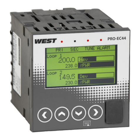
Eliwell EWTQ 905 User manual

GENERAL DESCRIPTION
EWTQ 905 is a “single loop” digital microproces-
sor-based controller, with ON/OFF, Neutral Zone
ON/OFF, PID single action, PID dual action
(direct and reverse) control and with AUTO-
TUNING FAST function and SELF-TUNING
function for PID control.
The process value is visualized on 4 red displays,
while the output status is indicated by 2 LED
displays.
The instrument is equipped with a 3 LED pro-
grammable shift indexes.
The instrument can have up to 2 outputs: relay
type or can drive solid state relays type (SSR).
Depending on the model required the input
accept:
• C: Thermocouples temperature probes (J,K),
mV signals (0..50/60 mV, 12..60 mV),
Thermoresistances PT100.
• E : Thermocouples temperature probes (J,K),
mV signals (0..50/60 mV, 12..60 mV),
Thermistors PTC and NTC.
• I : normalized analogue signals 0/4..20 mA
• V : normalized analogue signals
0..1 V, 0/1..5V, 0/2..10 V
PROGRAMMING
FAST PROGRAMMING OF THE SET POINT
This procedure permits rapid programming of
the Set Point (SP1) and possibly the alarm
thresholds (AL1).
• Push key set, then release it and the display
will visualise “SP1” alternatively to the pro-
grammed value.
To modify the value, press “UP” key to increase
it or the “DOWN” key to decrease it.
PLEASE NOTE: These keys change the value one
digit at a time but if they are pressed for more
than one second, the value increases or
decreases rapidly and, after two seconds in the
same condition, the changing speed increases in
order to allow the desired value to be reached
rapidly.
• Once the desired value has been reached, by
pushing key set it is possible to exit by the fast
programming mode or it is possible to visualise
the alarm thresholds.
• To exit the fast Set programming it is neces-
sary to push key set, after the visualisation of
the last Set Point, or alternatively, if no key is
pressed for approx. 15 seconds, the display will
return to normal functioning automatically.
PARAMETER PROGRAMMING
By pushing key set and holding it down for
approx. 2 sec. it is possible to enter into the
main selection menu.
Using the "UP" or DOWN” keys, it is then possi-
ble to roll over the selections:
• "OPEr" to enter into the operating parame-
ters menu;
• "ConF" to enter into the configuration para-
meters menu;
Once the desired item has been selected, push
key set to confirm.
Selecting "OPEr" and "ConF" gives the possibili-
ty of accessing other menus containing addi-
tional parameters and more precisely :
• "OPEr" - Operating parameters Menu: this
normally contains the Set Point parameters but
it can contain all the desired parameters.
• "ConF" - Configuration parameters Menu: this
contains all the operating parameters and the
functioning configuration parameters.
To enter the menu “OPEr”, select the option
“OPEr” and press the key set and the display
will now show “0”.
By pressing the “UP” and “DOWN” keys please
set number (password) 381 (see last page) and
press “set” key.
If the password is not correct the instrument
will return in previous regulation status.
If the password is correct the display will show
the parameter’s code (“ ]SP “) (first parameters’
group). Again using the “UP” and “DOWN” keys,
it is possible to select the desired group of
parameters.
USER INTERFACE
1 - Key set : This is used to access the pro-
gramming parameters and to confirm selec-
tion.
2 - Key DOWN : This is used to decrease the
values to be set and to select the parameters.
If the key is held down, the user returns to
the previous programming level until he exits
the programming mode.
3 - Key UP : This is used to increase the val-
ues to be set and to select the parameters. If
the key is held down, the user returns to the
previous programming level until he exits the
programming mode.
Outside the programming mode it permits
visualisation of the output control power.
4 - Key F : This is a key that can be set to :
Activate Auto-tuning and Self-tuning func-
tions;In “ConF” mode can be used to change
parameters’ visibility
5 - Led OUT1 : indicates the state of output
OUT1
6 - Led OUT2 : indicates the state of output
OUT2
7 - Led SET : when flashing, it indicates
access to the programming mode.
8 - Led AT/ST : indicates that the Self-tuning
function is activated (light on) or that Auto-
tuning (flashing ) is in progress.
9 - Led – Shift index: indicates that the
process value is lower than the one pro-
grammed on par. “AdE”.
10 - Led = Shift index: indicates that the
process value is within the range [SP+AdE ...
SP-AdE]
11 - Led + Shift index: indicates that the
process value is higher than the one set on
par. “AdE”.
EWTQ 905
digital temperature regulator 48x48
cod. 9IS23045
rel. 1/04
I
10
3
4
AT
9
5
ST
8
2
1
EWTQ 905
OUT2OUT1 -=+
6
SET
7
11
Fset

Once the desired value has been programmed,
push key set once more: the new value will be
memorised and the display will show only the
code of the selected parameter.
By using the “UP” or “DOWN” keys, it is then
possible to select a new parameter (if present)
and modify it as described above.
To select another group of parameters, keep the
“UP” or “DOWN” key setressed for approx. 2
sec., afterwards the display will return to visu-
alise the code of the group of parameters.
Release the key and by using the “UP” and
“DOWN” keys, it will be possible to select a new
group (if present).
To exit the programming mode, no key should
be pressed for approx. 20 seconds, or keep the
“UP” or “DOWN” pressed until exit from the
programming mode is obtained.
To enter the menu "ConF" a PASSWORD is
required.
At this request, enter, using keys “UP” and
“DOWN”, the number reported on the last page
of this manual and push key set.
If an incorrect password is entered, the instru-
ment returns to the previous control state.
If the password is correct, the display will visu-
alise the code identifying the first group of
parameters (“ ]SP “) and with keys “UP” and
“DOWN” it will be possible to select the desired
group of parameters
The programming and exit modes for the
“ConF” menu are the same as those described
for menu “OPEr”.
PARAMETERS PROGRAMMING LEVELS
The menu “OPEr” normally contains the para-
meters used to program the Set Point; however
it is possible to make all desired parameters
appear or disappear on this level, by following
this procedure:
Enter the menu “ConF” and select the parame-
ter to be made programmable or not program-
mable in the menu “OPEr”.
Once the parameter has been selected, if the
LED SET is switched off, this means that the
parameter is programmable only in the menu
“ConF”, if instead the LED is on, this means that
the parameter is also programmable in the
menu “OPEr”.
FUNCTIONS
MEASURING AND VISUALIZATION
All the parameters referring measurements are
contained in the group “]InP”.
Depending on the model required the input
accept:
• C: Thermocouples temperature probes (J,K),
mV signals (0..50/60 mV, 12..60 mV),
Thermoresistances PT100.
• E : Thermocouples temperature probes (J,K),
mV signals (0..50/60 mV, 12..60 mV),
Thermistors PTC and NTC.
• I : normalized analogue signals 0/4..20 mA
• V : normalized analogue signals
0..1 V, 0/1..5 V, 0/2..10 V
Depending on the model, using par. “SEnS”, it’s
possible to select the type of input probe,
which can be :
• for thermocouples J (J), K (CrAL)
• for thermoresistances Pt100 IEC (Pt1)
• for thermistors PTC KTY81-121 (Ptc) or NTC
103AT-2 (ntc)
• for normalised signals in current 0..20 mA
(0.20) or 4..20 mA (4.20)
• for normalised signals in tension 0..1 V (0.1),
0..5 V (0.5), 1..5 V (1.5), 0..10 V (0.10) or 2..10 V
(2.10).
- for normalised signals in tension 0..50 mV
(0.50), 0..60 mV (0.60), 12..60 mV (12.60).
We recommend to switch on and off the instru-
ment when these parameters are modified, in
order to obtain a correct measuring.
For the instruments with input for temperature
probes (tc, rtd) it’s possible to select, through
par. “Unit”, the unit of measurement (°C, °F)
and, through par. “dP” (Pt100, PTC and NTC
only) the desired resolution (0=1°; 1=0,1°).
Instead, with regards to the instruments with
normalised analogue input signals, it is first nec-
essary to program the desired resolution on par.
“dP” (0=1; 1=0,1; 2=0,01; 3=0,001) and then,
on par. "SSC", the value that the instrument
must visualise at the beginning of the scale (0/4
mA, 0/12 mV, 0/1 V o 0/2 V) and, on par. "FSC",
the value that the instrument must visualise at
the end of the scale (20 mA, 50 mV, 60 mV, 5 V
or 10 V).
The instrument allows for measuring calibration,
which may be used to recalibrate the instru-
ment according to application needs, by using
par. “OFSt” and “rot”.
Programming par. “rot”=1,000, in par. “OFSt” it
is possible to set a positive or negative offset
that is simply added to the value read by the
probe before visualisation, which remains con-
stant for all the measurements.
If instead, it is desired that the offset set should
not be constant for all the measurements, it is
possible to operate the calibration on any two
points.
In this case, in order to decide which values to
program on par. “OFSt” and “rot”, the following
formulae must be applied :
“rot” = (D2-D1) / (M2-M1)
“OFSt” = D2 - (“rot” x M2)
where:
M1 =measured value 1
D1 = visualisation value when the instrument
measures M1
M2 =measured value 2
D2 = visualisation value when the instrument
measures M2
It then follows that the instrument will visualise
: DV = MV x “rot” + “OFSt”
where: DV = visualised value MV= measured
value
Example 1: It is desired that the instrument visu-
alises the value effectively measured at 20° but
that, at 200°, it visualises a value lower than 10°
(190°).
Therefore : M1=20 ; D1=20 ; M2=200 ;
D2=190
“rot” = (190 - 20) / (200 - 20) = 0,944
“OFSt” = 190 - (0,944 x 200) = 1,2
Example 2: It is desired that the instrument visu-
alises 10° whilst the value actually measured is
0°, but, at 500° it visualises a 50° higher value
(550°).
Therefore : M1=0 ; D1=10 ; M2=500 ;
D2=550
“rot” = (550 - 10) / (500 - 0) = 1,08
“OFSt” = 550 - (1,08 x 500) = 10
By using par. “FiL” it is possible to program time
constant of the software filter for the input
value measured, in order to reduce noise sensi-
tivity (increasing the time of reading).
In case of measurement error, the instrument
supplies the power as programmed on par.
“OPE”.
This power will be calculated according to cycle
time programmed for the PID controller, while
for the ON/OFF controllers the cycle time is
automatically considered to be equal to 20 sec.
(e.g. In the event of probe error with ON/OFF
control and “OPE”=50, the control output will
be activated for 10 sec., then it will be deacti-
vated for 10 sec. and so on until the measure-
ment error remains.).
Again in the group “]PAn” the par. “AdE” is pre-
sent that defines the 3 led shift index function-
ing.
The lighting up of the green led = indicates that
the process value is within the range [SP+AdE
... SP-AdE], the lighting up of the led – indicates
that the process value is lower than [SP-AdE]
and the lighting up of the led + indicates that
the process value is higher than [SP+AdE].
EWTQ 905 2/8
PASSWORD
2 sec.
Hold for
SET/imposta
menu
" OPEr "
" ConF "
menu
Tenere premuto
per 2 sec.
EXIT /
USCITA
men˘
"ConF"
"OPEr"
or/oppure
Longer
Hold
2 sec.
Hold for
O
2 sec.
Hold for Next
Group
Previous
Group
PARAMETER GROUPS
Next
Parameter
Previous
Parameter
PARAMETERS
Value
Decrease
Value
Increase
SET PARAMETER
RO
R
GRUPPI PARAMETRI PARAMETRI IMPOSTA PARAMETRO
gruppo precedente
parametro
precedente
incrementa
valore
parametro
seguente
decrementa
valore
gruppo seguente
premere per 2sec
+ a lungo
premere

OUTPUTS CONFIGURATION
The instrument’s outputs can be programmed
by entering the group of parameters “]Out,
where the relative parameters “O1F” and “O2F”
(depending on the number of outputs available
on the instrument) are located.
The outputs can be set for the following func-
tions :
• Main control output (1.rEG)
• Secondary control output (2.rEG)
• Alarm output normally open (ALno)
• Alarm output normally closed (ALnc)
• Alarm output normally closed with led reverse
indication (ALni)
• Output deactivated (OFF)
The coupling outputs number outputs – number
alarms can be made in the group referring to
the alarm to the alarm (“]AL1”).
ON/OFF CONTROL (1REG)
All the parameters referring to the ON/OFF
control are contained in the group “]rEG”.
This type of control can be obtained by pro-
gramming par."Cont" = On.FS or = On.FA and
works on the output programmed as 1.rEG,
depending on the measure, on the active Set
Point “SP”, on the functioning mode "Func” and
on the hysteresis "HSEt".
The instrument carries out an ON/OFF control
with symmetric hysteresis if “Cont" = On.FS or
with asymmetrical hysteresis if “Cont” = On.Fa.
The control works in the following way : in the
case of reverse action, or heating
(“FunC”=HEAt), it deactivates the output, when
the process value reaches [SP + HSEt] in case of
symmetrical hysteresis, or [SP] in case of asym-
metrical hysteresis and is then activated again
when the process value goes below value [SP -
HSEt].
Vice versa, in case of direct action or cooling
("Func”=CooL), it deactivates the output, when
the process value reaches [SP - HSEt] in case of
symmetrical hysteresis, or [SP] in case of asym-
metrical hysteresis and is activated again when
the process value goes above value [SP + HSEt].
NEUTRAL ZONE ON/OFF CONTROL (1REG -
2REG)
All the parameters referring to Neutral Zone
ON/OFF control are contained in the group
“]rEG”.
This type of control can be obtained when 2
outputs are programmed respectively as 1rEG
and 2rEG and the par. “Cont” = nr .
The Neutral Zone control is used to control
plants in which there is an element which caus-
es a positive increase (ex. Heater, humidifier,
etc.) and an element which causes a negative
increase (ex. Cooler, de-humidifier, etc).
The control functions works on the pro-
grammed outputs depending on the measure-
ment, on the active Set Point “SP” and on the
hysteresis "HSEt".
The control works in the following way : it deac-
tivates the outputs when the process value
reaches the Set Point and it activates the output
1rEG when the process value goes below value
[SP - HSEt], or it activates the output 2rEG when
the process value goes above [SP + HSEt].
Consequently, the element causing a positive
increase has to be connected to the output pro-
grammed as 1rEG while the element causing a
negative increase has to be connected to the
output programmed as 2rEG.
If 2rEG output is used to control compressor is
possible to use the “Compressor Protection”
function that has the meaning to avoid com-
pressor “short cycles”.
This function allows a control by time on the
output 2rEG activation, independently by the
temperature control request.
The protection is a “delayed after deactivation”
type.
This protection permits to avoid the output
activation for a time programmable on par.
“CPdt” (expressed in sec.); the output activation
will occurs only after the elapsing of time
“CPdt”.
The time programmed on parameter “CPdt” is
counted starting from the last output deactiva-
tion.
Obviously, whether during the time delay
caused by the compressor protection function,
the regulator request should stop, the output
activation foreseen after time “CPdt” would be
erased.
The function is not active programming “CPdt”
=OFF.
The led relative to 2rEG output blinks during
the phases of output activation delay, caused by
“Compressor Protection” function.
SINGLE ACTION PID CONTROL (1REG)
All the parameters referring to PID control are
contained in the group “]rEG”.
The Single Action PID control can be obtained
by programming par."Cont" = Pid and works on
the output 1rEG depending on the active Set
Point “SP”, on the functioning mode "Func” and
on the instrument’s PID algorithm with two
degree of freedom.
In order to obtain good stability of the process
variable, in the event of fast processes, the cycle
time “tcr1” has to have a low value with a very
frequent intervention of the control output.
In this case use of a solid state relay (SSR) is
recommended for driving the actuator.
EWTQ 905 3/8
OUT
SP1
PV
off
ON
HEAt - On.FA
OUT
time
HSEt
SP1
PV
HSEt
time
CooL - On.FA
ON ON ON ON ON
off off off
CooL - On.FSHEAt - On.FS
ONON
OUT
SP1
off
PV
off
ON
HSEt
time
OUT ON
SP1
PV
ON
off off
ON
time
HSEt
HSEt HSEt
1.rEG 1.rEG
1.rEG1.rEG
0N
OUT 2.rEG
(cooling)
OUT 1.rEG
(heating)
SP1
PV
off
0N
off
off
off
0N time
HSEt
HSEt
,,
,,,,
,,,,,
,,,,,
,,,,
,,,
,
,,,
,,
,
,
,,
,
,,
,,
,
,,
,,,,
,,
,,
,,,,
,,
,
,,
,,
,
,,
,,
,
,,
,,,,
,,

The Single Action PID control algorithm fore-
sees the setting of the following parameters :
"Pb" – Proportional Band
"tcr1" – Cycle time of the output 1rEG
"Int" – Integral Time
"rS" – Manual Reset (if “Int =0 only)
"dEr" – Derivative Time
“FuOC” - Fuzzy Overshoot Control
This last parameter allows the variable over-
shoots at the start up of the process or at the
changing of the Set Point to be avoided.
Please remember that a low value on this para-
meter reduces the overshoot while a high value
increase it.
1: Value “FuOC” OK
2: Value “FuOC” too high
3: Value “FuOC” too low
DOUBLE ACTION PID CONTROL (1REG -
2REG)
All the parameters referring to PID control are
contained in the group “]rEG”.
The Double Action PID control is used to con-
trol plants where there is an element which
causes a positive increase (ex. Heating) and an
element which causes a negative increase (ex.
Cooling).
This type of control can be obtained when 2
outputs are programmed respectively as 1rEG
and 2rEG and the par. “Cont” = Pid.
The element causing a positive increase has to
be connected to the output programmed as
1rEG while the element causing a negative
increase has to be connected to the output pro-
grammed as 2rEG.
The Double Action PID control works on the
outputs 1rEG and 2rEG depending on the active
Set Point “SP” and on the instrument’s PID algo-
rithm with two degrees of freedom.
In order to obtain good stability of the process
variable, in case of fast processes, the cycle
times “tcr1” and “tcr2” have to have a low value
with a very frequent intervention of the control
outputs.
In this case use of solid state relays (SSR) to
drive the actuators is recommended.
The Double Action PID control algorithm needs
the programming of the following parameters :
• "Pb" – Proportional Band
• "tcr1" – Cycle time of the output 1rEG
• “tcr 2” – Cycle time of the output 2rEG
• "Int" – Integral Time
• "rS" – Manual Reset (if “Int =0 only)
• "dEr" – Derivative Time
• “FuOC” - Fuzzy Overshoot Control
• "Prat" - Power Ratio or relation between
power of the element controlled by output
2rEG and power of the element controlled by
output 1rEG.
AUTOTUNING AND SELFTUNING FUNCTIONS
All the parameters referring to the AUTO-TUN-
ING and SELF-TUNING functions are contained
in the group “]rEG”.
The AUTO-TUNING and SELF-TUNING functions
permit the automatic tuning of the PID con-
troller.
The AUTO-TUNING function permits the calcula-
tion of thePID parameters by means of a FAST
type tuning cycle and, at the end of this opera-
tion, the parameters are stored into the instru-
ment’s memory and remain constant during
control.
The SELF-TUNING function (rule based "TUNE-
IN") instead allows control monitoring and the
continuous calculation of the parameters during
control.
Both functions automatically calculate the fol-
lowing parameters :
"Pb" – Proportional Band
"tcr1" – Cycle time of the output 1rEG
"Int" – Integral Time
"dEr" – Derivative Time
“FuOC” - Fuzzy Overshoot Control
and, for the Double Action PID control, also :
“tcr 2” – Cycle time of the output 2rEG
"Prat" - Ratio P 2rEG/ P 1rEG
To activate the AUTO-TUNING function proceed
as follows :
1) Program and activate the desired Set Point.
2) Program par. "Cont" =Pid.
3) Program par. "Func" according to the process
to be controlled through output 1rEG.
4) Program an output as 2rEG if the instrument
controls a plant with double action
5) Program par. "Auto" as:
- "1” – if auto-tuning is desired automatically,
each time the instrument is switched on, on the
condition that the process value is lower (with
“Func” =HEAt) than [SP- |SP/2|] or higher (with
“Func” =CooL) than [SP+ |SP/2|].
- "2" – if auto-tuning is desired automatically,
the next time the instrument is switched on, on
the condition that the process value is lower
(with “Func” =HEAt) than [SP- |SP/2|] or higher
(with “Func” =CooL) than [SP+ |SP/2|], and
once the tuning is finished, the par. “Auto” is
automatically swapped to the OFF state
- "3" - if manual auto-tuning is desired, by
selecting par. “tunE” in the main menu or by
correctly programming key F as “USrb” = tunE.
In this case the auto-tuning starts without any
control on the process value condition. It is rec-
ommended to use this option, starting the auto-
tuning when the process value is as far as possi-
ble from the Set Point because, in order to fea-
ture the Auto-tuning FAST with its best perfor-
mances , it is preferable to respect this condi-
tion.
- "4" - if it’s desired to activate the autotuning
automatically at the end of programmed Soft-
Start cycle. The Autotuning will start at the con-
dition that the process value is lower (with
“Func” =HEAt) than [SP- |SP/2|] or higher (with
“Func” =CooL) than [SP+ |SP/2|].
6) Exit from the parameter programming.
7) Connect the instrument to the controlled
plant.
8) Activate the Auto-tuning by selecting par.
“tunE” in the main menu (or by correctly pro-
gramming key F ).
At this point the Auto-tuning function is activat-
ed and is indicated by the flashing led AT/ST.
The regulator carries out several operations on
the connected plant in order to calculate the
most suitable PID parameters.
If “Auto” = 1 or “Auto” = 2, and if, at the Auto-
tuning start, the condition for the lower process
value is not found (with “Func” =HEAt) than
[SP- |SP/2|] or higher (with “Func” =CooL) than
[SP+ |SP/2|], the display will show “ErAt” and
the instrument will be swapped to normal con-
trol conditions according to the previously pro-
grammed parameters.
The Auto-tuning cycle duration has been limited
to 12 hours maximum.
If Auto-tuning is not completed within 12 hours,
the instrument will show "noAt" on the display.
In case of probe error, the instrument automati-
EWTQ 905 4/8
0N
tcr1
1.rEG
(HEat)
SP1
PV
tcr1
off
tcr1tcr1tcr1 tcr1
0N
off off
0N
offoff
0N 0N
tcr1
off
0N 0N
time
OUT
2
1
3
SP1
PV
time

cally stops the cycle in progress.
The values calculated by Auto-tuning are auto-
matically stored in the instrument’s memory at
the end of the correct PID parameters tuning.
To activate the SELF-TUNING function proceed
as follows
1) Program and activate the desired Set Point.
2) Program par. "Cont" =Pid.
3) Program par. "Func" according to the process
to be controlled through output 1rEG.
4) Program an output as 2rEG if the instrument
controls a dual-action plant
5) Program par. "SELF" = yES
6) Exit from the parameter programming.
7) Connect the instrument to the controlled
plant.
8) Activate Self-tuning selecting par. “tunE” in
the main menu (or by correctly programming
key F).
When the Self-tuning function is active, the led
AT/ST is permanently lit up and all the PID para-
meters ("Pb", "Int", "dEr", etc.) are no longer
visualized.
To stop the Auto-tuning cycle or deactivate the
Self-tuning function select one of the control
types : "rEG", "OPLO" or "OFF" from the menu
“SEL”. If the instrument is switched off during
Auto-tuning or with the Self-tuning function
activated, these functions will remain activated
the next time it is switched on.
DYNAMIC SET POINT (RISE RAMP)
All the parameters referring to the ramps func-
tioning are contained in the group “]rEG”.
It is possible to reach the set point in a prede-
termined time (in any case longer than the time
the plant would naturally need). This could be
useful in those processes (heating or chemical
treatments, etc.) where the set point has to be
reached gradually, in a predetermined time.
Once the instrument has reached the first Set
Point (SP1) it is possible to have automatic
switching to the second Set Point (SP2) after a
set time, thus obtaining a simple automatic
thermic cycle.
These functions are available for all the pro-
grammable controls (PID single and double
action, ON/OFF and Neutral Zone ON/OFF).
The function is determined by the following
parameter:
"SLor" - Gradient of rise ramp (Process value <
Set point) expressed in unit/minute.
Note: In case of PID control, if Auto-tuning is
desired whilst the ramp function is active, this
will not be carried out until the tuning cycle has
been completed.
It is therefore recommended that Auto-tuning
be started avoiding activating the ramp function
and, once the tuning is finished, deactivate
Auto-tuning (“Auto” = OFF), program the
desired ramps and, if it automatic tuning is
desired, enable the Self-tuning function.
Examples with starts from values lower than
SP and with decreasing of SP.
EWTQ 905 5/8
LoAb
off
ON
AL1
AL1
PV
HiAb
HAL1
time
off
ON
AL1
PV
time
HAL1
off off
ON
OUT
off off
ON
OUT
AL1
SP1
[Unit]
PV
SP1 Value
change
SP1
time [min.]
SLor SLor
LoAb = ABSOLUTE LOW ALARM: The alarm is
activated when the process value goes below
the alarm threshold set on parameter "AL1”.
With this mode is possible to program the mini-
mum and the maximum set of “AL1” by “AL1L”
and “AL1H” parameters.
HiAb = ABSOLUTE HIGH ALARM: The alarm is
activated when the process value goes higher
than the alarm threshold set on parameter
"AL1". With this mode is possible to program
the minimum and the maximum set of “AL1”
by “AL1L” and “AL1H” parameters.
LodE
ON
off
PV
SP1
-AL1
HAL1
time
off
ON
SP1
AL1
PV
HidE
time
HAL1
ON
off off off off
ON
OUT
AL1 OUT
AL1
LHAb = ABSOLUTE BAND ALARM: The alarm
is activated when the process value goes under
the alarm threshold set on parameter "AL1L" or
goes higher than the alarm threshold set on
parameter "AL1H".
LodE = DEVIATION LOW ALARM: The alarm is
activated when the process value goes below
the value [SP + AL1]. With this mode is possible
to program the minimum and the maximum set
of “AL1” by “AL1L” and “AL1H” parameters.
LHAb
ON
off
AL1H
AL1L
PV
ON
time
off
HAL1
HAL1
SP1
AL1L
AL1H
PV
time
LHdE
HAL1
HAL1
off off
ON ON
off off
OUT
AL1 OUT
AL1
HidE = DEVIATION HIGH ALARM: The alarm is
activated when the process value goes above
the value [SP + AL1]. With this mode is possible
to program the minimum and the maximum set
of “AL1” by “AL1L” and “AL1H” parameters.
LHdE = DEVIATION BAND ALARM: The alarm
is activated when the process value goes below
the value [SP + AL1L] or goes above than the
value [SP + AL1H]
ALARM FUNCTIONING (AL1)
The alarm is depending on the process value
(AL1) and before to set his functioning it’s nec-
essary to establish to which output the alarm
has to correspond to.
First of all it’s necessary to configure, in the
parameters group “]Out”, the parameters rela-
tive to the outputs required as alarm (“O1F” ,
“O2F”) programming the parameter relative to
the desired output as follows :
= ALno if the alarm output has to be ON when
the alarm is active, while it’s OFF when the
alarm is not active
= ALnc if the alarm output has to be ON when
the alarm is not active, while it’s OFF when the
alarm is active
= ALni if the alarm output has to be ON when
the alarm is not active, while it is OFF when the
alarm is active but with reverse led indication
(led ON= alarm OFF).
Have now access at the group “]AL1”, and pro-
gram on par. “OAL1” , to which output the
alarm signal has to be sent.
The alarm functioning is instead defined by
parameters (see Group “]AL1” (parameters
relative to alarm AL1):
"AL1t" – ALARM TYPE : the alarm output can behave in six different ways.

USE CONDITIONS
The instrument CANNOT be used in dangerous
environments (flammable or explosive) without
adequate protection.
The installer must ensure that EMC rules are
respected, also after the instrument installation,
if necessary using proper filters.
Whenever a failure or a malfunction of the
device may cause dangerous situations for per-
sons, thing or animals, please remember that
the plant has to be equipped with additional
devices which will guarantee safety.
MECHANICAL MOUNTING
The instrument, in DIN case 48 x 48 mm, is
designed for flush-in panel mounting.
Make a hole 45 x 45 mm and insert the instru-
ment, fixing it with the provided special bracket.
We recommend that the gasket is mounted in
order to obtain the front protection degree as
declared. Avoid placing the instrument in envi-
ronments with very high humidity levels or dirt
that may create condensation or introduction of
conductive substances into the instrument.
Ensure adequate ventilation to the instrument
and avoid installation in containers that house
devices which may overheat or which may cause
the instrument to function at a higher tempera-
ture than the one permitted and declared.
Connect the instrument as far away as possible
from sources of electromagnetic disturbances
such as motors, power relays, relays, solenoid
valves, etc.
The instrument can be removed from its hous-
ing from the front side : it is recommended that
the instrument be disconnected from the
power supply when it is necessary to carry out
this operation.
ELECTRICAL CONNECTIONS
Warning! Never work on electrical connections
when the machine is switched on.
The instrument is equipped with screw terminal
boards for connection of electrical cables (one
conductor only per terminal for power connec-
tions): for the capacity of the terminals, see the
label on the instrument. The relay contacts are
voltage free.
Do not exceed the maximum current allowed;
in case of higher loads, use an appropriate con-
tactor. Make sure that power supply voltage
meets the instrument voltage.
It is also recommended that all the electrical
circuits connected to the instrument must be
protect properly, using devices (ex. fuses) pro-
portionate to the circulating currents.
It is strongly recommended that cables with
proper insulation, according to the working
voltages and temperatures, be used.
Furthermore, the input cable of the probe has
to be kept separate from line voltage wiring. If
the input cable of the probe is screened, it has
to be connected to the ground with only one
side.
TECHNICAL DATA - ELECTRICAL DATA
Power supply: 24, 115, 230 VAC, 24 VAC/VDC,
100... 240 VAC +/- 10%
Frequency AC: 50/60 Hz
Power consumption: 5 VA approx.
Input/s: 1 input for temperature probes: tc J,K;
RTD Pt 100 IEC; PTC KTY 81-121 (990 W @ 25
°C); NTC 103AT-2 (10KW @ 25 °C) or mV sig-
nals 0...50 mV, 0...60 mV, 12 ...60 mV or normal-
ized signals 0/4...20 mA, 0..1 V, 0/1...5 V ,
0/2...10 V.
Normalized signals input impedance: 0/4..20
mA: 51 W; mV and V: 1 MW
Output/s: Up to 2 outputs. Relay SPST-NO (8 A-
AC1, 3 A-AC3 / 250 VAC) ; or in tension to drive
SSR (8mA/ 8VDC).
Auxiliary supply output: 10 VDC / 20 mA Max.
Electrical life for relay outputs: 100000 operat.
Installation category: II
Measurement category: I
Protection class against electric shock: Class II
for Front panel
Insulation: Reinforced insulation between the
low voltage section (supply and relay outputs)
and the front panel; Reinforced insulation
between the low voltage section (supply and
relay outputs) and the extra low voltage section
(inputs, SSR outputs); No insulation between
input and SSR outputs.
MECHANICAL DATA
Housing: Self-extinguishing plastic, UL 94 V0
Dimensions: 48 x 48 mm DIN, depth 98 mm
Weight: 225 g approx.
Mounting: Flush in panel in 45 x 45 mm hole
Connections: 2 x 1 mm2 screw terminals block
Degree of front panel protection : IP 54 mount-
ed in panel with gasket
Pollution situation: 2
Operating temperature: 0 ... 50 °C
Operating humidity: 30 ... 95 RH% without con-
densation
Storage temperature: -10 ... +60 °C
FUNCTIONAL FEATURES
Control: ON/OFF, single and double action PID
Measurement range: according to the used
probe (see range table)
Display resolution: according to the probe used
1/0,1/0,01/0,001
Overall accuracy: +/- 0,5 % fs
Sampling rate: 130 ms.
Display: 4 Digit Red h 12 mm
PANEL CUT-OUT
EWTQ 905 6/8
PLEASE NOTE: The technical data included in this
document, related to measurement (range, accu-
racy, resolution, etc.) refer to the instrument
itself, and not to its equipment such as, for exam-
ple, sensors.
This means, for example, that sensor(s) error(s)
shall be added to the instrument’s one.
LIABILITY AND RESIDUAL RISKS
Eliwell & Controlli srl shall not be liable for
any damages deriving from:
- installation/use other than that prescribed
and, in particular, that which does not com-
ply with safety standards anticipated by regu-
lations and/or those given herein;
- use on boards which do not guarantee ade-
quate protection against electric shock, water
or dust under the conditions of assembly
applied;
- use on boards which allow access to dan-
gerous parts without the use of tools;
- tampering with and/or alteration of the
products;
DISCLAIMER
This manual and its contents remain the sole
property of Eliwell & Controlli s.r.l., and shall
not be reproduced or distributed without
authorization. Although great care has been
exercised in the preparation of this docu-
ment, Eliwell & Controlli s.r.l., its employees
or its vendors, cannot accept any liability
whatsoever connected with its use. Eliwell &
Controlli s.r.l. reserves the right to make any
changes or improvements without prior
notice.
45
min. 15 mm
PANEL CUTOUTS
RECOMMENDED
45
min. 15 mm

EWTQ 905 7/8
PARAMETERS TABLE
Par. Description Range Def.
Group “]SP” (parameters relative to the Set Point)
1 SP1 Set Point SPLL ÷ SPHL 0
2 SPLL Low Set Point -1999 ÷ SPHL -1999
3 SPHL High Set Point SPLL ÷ 9999 9999
Group “]InP” (parameters relative to the measure input)
4 SEnS Probe type input C :
J / CrAL / S / Ir.J / Ir.CA / Pt1 / 0.50 / 0.60 / 12.60 J
input E :
J / CrAL / S /Ir.J / Ir.CA / Ptc/ ntc / 0.50 / 0.60 / 12.60 Ptc
input I :
0.20 / 4.20 4.20
input V :
0.1 /0.5 / 1.5 / 0.10 / 2.10 0.10
5 SSC Low scale limit in case of input with V / I signals -1999 ÷ FSC 0
6 FSC High scale limit in case of input with V / I signals SSC ÷ 9999 0
7 dP Number of decimal figures Pt1 / Ptc / ntc: 0 / 1
norm sig.: 0 ÷ 3 0
8 Unit Temperature unit of measurement °C / °F °C
9 FiL Input digital filter 0FF÷ 20.0 sec. 0.1
10 OFSt Measuring Offset -1999 ÷ 9999 0
11 rot Rotation of the measuring straight line 0.000 ÷ 2.000 1.000
12 OPE Output power in case of measuring error -100 ÷ 100% 0
Group “]Out” (parameters relative to the outputs)
13 O1F Functioning of output 1
1.rEG / 2.rEG ALno / ALnc ALni / OFF 1.rEG
14 O2F Functioning of output 2 1.rEG / 2.rEG ALno / ALnc ALni / OFF ALno
Group “]AL1” (parameters relative to alarm AL1)
15 OAL1 Output where alarm AL1 is addressed Out1 / Out2 /OFF Out2
16 AL1t Alarm AL1 type LoAb / HiAb LHAb / LodE HidE / LHdE LoAb
17 AL1 Alarm AL1 threshold AL1L÷ AL1H 0
18 AL1L Low threshold band alarm AL1 or
Minimum set alarm AL1 for high or low alarm -1999 ÷ AL1H -1999
19 AL1H High threshold band alarm AL1 or
Maximum set alarm AL1 for high or low alarm AL1L ÷ 9999 9999
20 HAL1 Alarm AL1 hysteresis OFF ÷ 9999 1
21 AL1d Activation delay of alarm AL1 OFF ÷ 9999 sec. OFF
22 AL1i Alarm AL1 activation in case of measuring error no / yES no
Group “]rEG” (parameters relative to the control)
23 Cont Control type Pid / On.FA On.FS / nr Pid
24 Func Functioning mode output 1rEg HEAt / CooL HEAt
25 HSEt Hysteresis of ON/OFF control 0 ÷ 9999 1
26 CPdt Compressor Protection time for 2.rEG OFF÷ 9999sec. 0
27 Auto Autotuning Fast enable OFF / 1 / 2 / 3 / 4 1
28 SELF Selftuning enable no / yES no
29 Pb Proportional band 0 ÷ 9999 50
30 Int Integral time OFF ÷ 9999 sec. 200
31 dEr Derivative time OFF÷ 9999 sec. 50
32 FuOc Fuzzy overshoot control 0.00 ÷ 2.00 0,5
33 tcr1 Cycle time of output 1rEg 0.1 ÷ 130.0 sec. 20,0
34 Prat Power ratio 2rEg / 1rEg 0.01 ÷ 99.99 1.00
35 tcr2 Cycle time of 2rEg 0.1 ÷ 130.0 sec. 10.0
36 rS Manual reset -100.0÷100.0 % 0.0
37 SLor Gradient of rise ramp 0.00 ÷ 99.99 / InFunit/min. InF
Group “]PAn” (parameters relative to the user interface)
38 AdE Shift value for the shift index functioning OFF...9999 2
EWTQ 905 WIRING DIAGRAM
EWTQ 905
6
5
4
3
2
PtC/NtC
Pt100 / Ni100
TcJ / TcK
+–
1 2 3
12
11
10
9
81 2 3 12
17
1 2 3 4
V
+
I
0...1V
0/2...10V
0/1...5V
4…20 mA
SUPPLY
OUT1
OUT2
TcJ / TcK
+–
12
active
1 2 3 4
V
-
I
+10V
0...1V
0/2...10V
0/1...5V
4…20 mA passive
with ext gen.
TERMINALS
INPUTS
1 - 2 TCJ/TCK 1 +; 2 -
2 - 3 Pt100/Ni100
1 - 2 TCJ/TCK 1 +; 2 -
1 - 2 - 3 PtC/NtC
1 - 2 0…1V; 0/1…5V; 0/2…10V 1 +;
1 - 2 0/4…20mA active 1 +;
1 - 4 4…20mA passive 4+ (+10Vdc)
OUTPUTS
7 - 8 SUPPLY
9 - 10 OUT2 9 COMMON; 10 N.O.
11 - 12 OUT1 11 COMMON; 12 N.O.

EWTQ 905 8/8
Error
- - - -
uuuu
oooo
ErAt
noAt
ErEP
Reason
Probe interrupted
The measured variable is under the probe’s limits (under-range)
The measured variable is over the probe’s limits (over-range)
Auto-tuning not possible because the process value is higher (with “Func” =HEAt)
than [SP- |SP/2|] or lower (with “Func” =CooL) than [SP+ |SP/2|].
Auto-tuning not finished within 12 hours
Possible anomaly of the EEPROM memory
ERROR SIGNALLING
Action
Verify the correct connection
between probe and instrument
and then verify the correct func-
tioning of the probe
Restart Auto-tuning when the
process value conditions allow it
Check the working of probe and
actuator and try again to start
Auto-tuning
Push key set
ALARMS
Eliwell & Controlli s.r.l.
via dell'Industria, 15 Zona Industriale Paludi
32010 Pieve d'Alpago (BL) ITALY
Telephone +39 0437 986111
Facsimile +39 0437 989066
Internet http:/www.eliwell.it
1/2004 eng
cod. 9IS23045
In error conditions, the instrument provides an output power as
programmed on par “OPE” and activates the desired alarms, if
the relative parameters “ALni” have been programmed = yES.
44.5
98
48
OUT2
48
ST
AT
OUT1 -+
=
9.5
SET
EWTQ 905
Fset
MAX 9 mm
PANEL + GASKET BRACKET TYPE 1 BRACKET TYPE 2
,,,
,,,,
,,,,,
,,,,
,,,
MECHANICAL DIMENSIONS,
PANEL CUT-OUT AND
MOUNTING [MM]
INPUT
tc J
tc K
Pt100 (IEC)
PTC (KTY81-121)
NTC (103-AT2)
0..20 mA
4..20 mA
0 ... 50 mV
0 ... 60 mV
12 ... 60 mV
0 ... 1 V
0 ... 5 V
1 ... 5 V
0 ... 10 V
2 ... 10 V
available on
models:
C,E
C,E
C,E
E
E
I
I
C,E
C,E
C,E
V
V
V
V
V
MEASURING RANGE TABLE
input
“dP”= 1, 2, 3
- - - -
- - - -
-199.9 ... 850.0 °C
-199.9 ... 999.9 °F
-55.0 ... 150.0 °C
-67.0 ...302.0 °F
-50.0 ... 110.0 °C
-58.0 ... 230.0 °F
-199.9 ... 999.9
-19.99 ... 99.99
-1.999 ... 9.999
-199.9 ... 999.9
-19.99 ... 99.99
-1.999 ... 9.999
-199.9 ... 999.9
-19.99 ... 99.99
-1.999 ... 9.999
-199.9 ... 999.9
-19.99 ... 99.99
-1.999 ... 9.999
-199.9 ... 999.9
-19.99 ... 99.99
-1.999 ... 9.999
-199.9 ... 999.9
-19.99 ... 99.99
-1.999 ... 9.999
-199.9 ... 999.9
-19.99 ... 99.99
-1.999 ... 9.999
-199.9 ... 999.9
-19.99 ... 99.99
-1.999 ... 9.999
-199.9 ... 999.9
-19.99 ... 99.99
-1.999 ... 9.999
-199.9 ... 999.9
-19.99 ... 99.99
-1.999 ... 9.999
MEASURING RANGE
input
“dP” = 0
0 ... 1000 °C
32 ... 1832 °F
0 ... 1370 °C
32 ... 2498 °F
-200 ... 850 °C
-328 ... 1562 °F
-55 ... 150 °C
-67 ... 302 °F
-50 ... 110 °C
-58 ... 230 °F
-1999 ... 9999
-1999 ... 9999
-1999 ... 9999
-1999 ... 9999
-1999 ... 9999
-1999 ... 9999
-1999 ... 9999
-1999 ... 9999
-1999 ... 9999
-1999 ... 9999
parameter
SenS=
J
CrAl
Pt1
Ptc
ntc
0.20
4.20
0.50
0.60
12.60
0.1
0.5
1.5
0.10
2.10
EWTQ 905 PASSWORD = 381
Table of contents
Other Eliwell Temperature Controllers manuals
