Eljen GSF User manual


2016 British Columbia Design & Installation Manual 2 www.eljen.com
Table of Contents
Note: Please make sure you are using the most current version of this manual by going to www.eljen.com
SUBJECT PAGE
Introduction 3
GSF System Description 4
Glossary of Terms 5
1.0 GSF System Sizing 7
2.0 Design Guidelines 8
2.1 Basic System Design 8
2.2 Level Site Systems 10
2.3 Sloped Site Systems 10
2.4 Pumped Systems 10
2.5 System Venting 11
2.6 Commercial Systems 13
2.7 GSF Design Considerations for Replacing Failed Systems 15
2.8 Required Notes on Design Plans 16
3.0 System Installation Guidelines 17
3.1 General System Installation Guidelines 17
3.2 Trench and In-Ground Bed System Installation Instructions 18
3.3 Raised or Fill System Installation Instructions 19
3.4 Serial Distribution on Sloped System Installation Instructions 20
4.0 Treated Effluent Sampling Port Installation 21
Drawings and Tables
Figure 1 GSF System Operation 4
Figure 2 Vent Details for Gravity, Demand, Pressure Distribution Systems 12
Figure 3 Air By-Pass Line Detail for Venting of Pumped Systems 12
Figure 4-5 System Sampling Port Installation Drawings 21-22
Figure 6 Vertical Separation to Limiting Conditions 23
Figure 7 A42 Trench Cross Section 23
Figure 8 A42 Butterfly Trench Configuration 24
Figure 9 A42 Module End-to-End Separation 24
Figure 10 A42 Bed Cross Section 25
Figure 11 Example Level Bed Plan View 25
Figure 12 A42 Raised Bed (Sand Mound) Cross Section 26
Figure 13 Example Raised Bed on Slope 26
Figure 14 Example Sequential Loading Outlet Setup in a Drop Box 27
Figure 15 Pressure Distribution Lateral Layout 27
Table 1 Eljen GSF Specified Sand 6
Table 2 Standard GSF Sizing Table – All Applications 7

2016 British Columbia Design & Installation Manual 3 www.eljen.com
Introduction
This manual provides design and installation information for the Eljen GSF (Geotextile Sand Filter) System
using the GSF A42 module within the design criteria as required in the BC Sewerage System Regulation
and the BC Sewerage System Standard Practice Manual (SPM) - Version 3. All design suggestions
contained herein are compliant with the BC SPM-V3.
More commonly known as an “In-Ground Treatment System”, the Eljen GSF in BC is referred to as a
“CTDS” or Combined Treatment and Dispersal System as detailed in the SPM-V3. The Eljen GSF is the
only CTDS that meets the requirements of the SPM-V3 demands for both gravity and pressure distribution.
The Eljen GSF system technology is derived from research conducted by nationally recognized engineering
scientists from the University of Connecticut. Eljen Corporation has over 30 years of success in the onsite
wastewater industry, with tens of thousands of systems currently in use worldwide. The GSF is recognized
and approved by regulatory officials and experts in the industry as one of the most reliable secondary
treatment technologies in the marketplace today. The system specifications in this manual are founded on
this research and proven long term performance history.
The GSF technology is based on scientific principles which state that improved effluent quality provides
increased soil absorption rates. GSF’s proprietary two-stage Bio-Matt™ pre-filtration process improves
effluent quality while increasing reliability and ease of operation.
The Eljen GSF has been tested and certified by NSF to NSF/ANSI Standard 40. Third-party independent
testing data has shown that the Eljen GSF provides advanced treatment of septic tank effluent to less than
10 mg/l BOD and 10 mg/l TSS.
The Eljen GSF Geotextile Sand Filter

2016 British Columbia Design & Installation Manual 4 www.eljen.com
GSF System Description
The Eljen GSF Geotextile Sand Filter system is a cost-effective improvement over other septic treatment
technologies. Comprised of a proprietary two-stage Bio-Matt™ treatment process, the geotextile modules apply
a better-than-secondary treated effluent to the soil, increasing the soil’s absorption rate. The result is superior
treatment in a smaller soil absorption area.
In British Columbia under the Sewerage System Regulation the Eljen GSF is a Type 2 Secondary Treatment
System with the added benefit of reduced fecal coliform and nitrogen. In the Standard Practice Manual –
Version 3, the GSF is categorized as a Combined Treatment and Dispersal System.
How the GSF System Works
Primary Treatment Zone
Perforated pipe is centered above the GSF module to distribute septic effluent over and into
corrugations created by the cuspated core of the geotextile module. For pressurized systems a
pressure line is added inside the perforated pipe.
Septic effluent is filtered through the Bio-Matt fabric. The module’s unique design provides
increased surface area for biological treatment that greatly exceeds the module’s footprint.
Open-air channels within the module support aerobic bacterial growth on the modules geotextile
fabric interface, surpassing the surface area required for traditional absorption systems.
An anti-siltation geotextile fabric covers the top and sides of the GSF module and protects the
Specified Sand and soil from clogging, while maintaining effluent storage within the module.
Secondary Treatment Zone
Effluent drips into the Specified Sand layer and supports unsaturated flow into the native soil. This
Specified Sand/soil interface maintains soil structure, thereby maximizing the available absorption
interface in the native soil. The Specified Sand supports nitrification of the effluent, which reduces
oxygen demand in the soil, thus minimizing soil clogging from anaerobic bacteria.
The Specified Sand layer also protects the soil from compaction and helps maintain cracks
and crevices in the soil. This preserves the soil’s natural infiltration capacity, which is
especially important in finer textured soils, where these large channels are critical for long-
term performance.
The native soil then provides final treatment and filtration prior to groundwater recharge.
Figure 1: GSF System Operation

2016 British Columbia Design & Installation Manual 5 www.eljen.com
Glossary of Terms
Note: The words and terms below, where used in this manual, have the following meanings:
A42 GSF Module Dimensions – (L x W x H) - 122 cm x 61 cm x 18 cm (48” x 24” x 7”) The
individual module of a GSF system. The module is comprised of a cuspated
plastic core and corrugated geotextile fabric.
Biofabric Special filter fabric within the Geotextile Sand Filter Modules upon which the
primary biomat layer forms.
Cover Fabric The geotextile cover fabric (provided by manufacturer) that is placed over the
GSF modules.
Cuspated Core The rigid plastic core of the GSF module. It separates the geotextile Biofabric
and creates downward infiltration channels and upward aeration channels where
primary filtration and biological treatment of the septic effluent occurs. The
curvilinear shape of the cuspations offers increased treatment surface area and
greater effluent storage.
*CTDS Combined Treatment and Dispersal System
*Daily Design Flow (DDF) As defined in the SPM – V3, is the flow rate used for sizing a wastewater
system taking into account mass loading and peak flows. The estimated peak
flow per A-42 unit that is used to size a GSF system using residential strength
waste is 72 liters per day per module.
Distribution Box (Or D-Box) A plastic or concrete box that receives effluent from a septic tank or
pump tank and splits the flow to pipes placed above the GSF modules.
Drop Box (Spill-Over) A plastic or concrete box that receives effluent and delivers flow to
pipes placed above the GSF modules before spilling over to further down-slope
Drop Boxes. See also Serial Distribution.
Flow Equalizer Also known as speed-levelers - Special insert placed in the end of distribution
pipes at the distribution box to minimize effects of settling and out of level
installation of the D-Box.
GAC Filter Granular Activated Carbon (Charcoal) Filter used on vents to remove septic
odors.
GSF Geotextile Sand Filter - Includes the Eljen Geotextile Filter modules, a 15 cm
sand layer along the base and sides of the modules and the cover fabric. The
GSF is a Type 2 Secondary CTDS as defined in the SPM – V3.
LTAR Long Term Acceptance Rate - LTAR is the average equilibrium absorption rate
for effluent in a system, usually expressed in liters per day per square meter.
*Mound Sand A sand specification as detailed in the SPM-V3 along with Clean Course Sand
and Sand Filter Course Sand.
NSF/ANSI Standard A standard for residential wastewater treatment systems. Visit www.nsf.org for
40 more information.
*Point of Application The Point of Application is the interface surface(s) where the secondary treated
effluent passes from the Eljen GSF System to the native (or tertiary engineered
media) receiving soils. See also: Infiltrative Surface as defined in the SPM-V3.

2016 British Columbia Design & Installation Manual 6 www.eljen.com
Glossary of Terms
Serial Distribution Also known as Sequential Distribution, are designs common to sloping sites
where GSF lines that are laid on contour receive effluent from a series of “spill-
overs” at different elevations. Effluent floods up-slope lines and then spills
excess effluent to down-slope lines. See also Drop Box.
*SHWT Seasonal High Water Table
SPM-V3 The Sewerage System “Standard Practice Manual” Version 3 as published
by the Ministry of Health Services – BC dated September 2014. As referenced in
the Sewerage System Regulation (SSR) Section 8 (3).
SSR Sewerage System Regulation – The BC Provincial Regulation that applies to
the construction and maintenance of all septic systems under 22,700 L/d DDF.
For more detail see actual BC Reg. 326/2004 including amendments to BC Reg.
Specified Sand
The sand specification used for the testing of the GSF system, as such, to
ensure proper system operation, the system must be installed using the
following; ASTM C33 sand with less than 10% passing #100 sieve and less than
5% passing #200 sieve. Listed below is a chart outlining the sieve requirements
for the Specified Sand.
TABLE 1: Eljen GSF Specified Sand
Eljen GSF
Specified Sand Requirements
Sieve Size
Sieve
Square Opening
Size
Specification
Percent Passing
0.375”
9.5 mm
100.0
#4
4.75 mm
95.0 –100.0
#8
2.36 mm
80.0 –100.0
#16
1.18 mm
50.0 –85.0
#30
600 µm
25.0 –60.0
#50
300 µm
5.0 –30.0
#100
150 µm
0 –10.0
#200
75 µm
0 –5.0
Note: Request a sieve analysis from your material supplier to ensure that
the system sand meets the specification requirements listed above.
Width & Length The system width is the Specified Sand dimension perpendicular to the GSF
module rows. The system length is measured parallel to the rows of GSF
modules.
Wire Clamps Wire Clamps are used to secure perforated pipe above the GSF modules.
*See also SPM-V3 section 1-1.1 Glossary

2016 British Columbia Design & Installation Manual 7 www.eljen.com
1.0 GSF System Sizing
TABLE 2: Standard GSF Sizing Table - All Applications
Table 1 shows the minimum number of A42 modules required for residential systems up to 6 bedrooms.
For other flow rates and number of bedrooms not shown in the table above, divide the DDF by
72L/d/module and round up to the next whole number. For residential homes a minimum of 6 modules
per bedroom is required. If the DDF divided by 72 L/d/module equals less than 6 modules per bedroom,
round up to the minimum number of A42 modules required per bedroom.
To cover the larger basal areas required by slower soils, in beds and mounds increase the edge to edge
separation between runs to a maximum of 91 cm. For all systems, the Eljen GSF modules can be
separated by up to 91 cm end-to-end to increased effective basal area without additional modules. All
perforated holes not discharging at least 15 cm onto a GSF module must be sealed. See Figure 9 for a
suggested method of sealing holes. For assistance with very large basal area requirements please
contact the Eljen Technical Representative, BWD Engineering Inc.
In a single row, the width can be increased by 91 cm for a total width of 182 cm. Modules in a single row
can also be separated end-to-end by up to 91 cm to further increase basal area coverage.
For non-residential applications, see Section 2.6 Commercial Systems.
Bedrooms
1
2
3
4
5
6
Standard Daily Design Flow liters/day
700
1000
1300
1600
1900
2200
Recommended Number of Modules
12
16
20
24
30
36

2016 British Columbia Design & Installation Manual 8 www.eljen.com
2.0 Design Guidelines
2.1 Basic System Design
2.1.1 DISPOSAL FIELD SIZE: The total basal area required is site specific and determined by the
Daily Design Flow (DDF) and soils analysis as specified in the SPM or by a professional.
The GSF system is a Type 2 - Combined Treatment and Dispersal System thus requiring about ½ the
field size of a standard Type 1 stone and pipe system or chamber system.
The number of GSF modules required (See 2.1.10) typically fits the required basal area and can be
configured to properly cover any shape required and is the same for trench, bed or mound systems.
In beds and mounds, a minimum of 30 cm separation is required between parallel rows of a GSF to
utilize sidewall infiltration area.
Maximum edge-to-edge and end-to-end separation for Modules in all applications is 91 cm.
2.1.2 Vertical Separation: As required by the BC Sewerage System SPM- V3 or as specified by a
professional.
Note in Version 3 of the SPM, an additional 15 cm of Vertical Separation has been added, in some soil
categories, for Type 2 systems that reduce or remove the Type 1 bio-mat. In the case of the Eljen GSF, the
bio-mat is retained allowing for the required Vertical Separation to remain the same as Type 1 designs.
2.1.3 SPECIFIED SAND SPECIFICATION FOR ALL SYSTEMS: The first 15 cm of Specified Sand
immediately under, between rows and around the perimeter of the GSF system must be ASTM C33
WASHED CONCRETE SAND WITH LESS THAN 10% PASSING A #100 SIEVE AND LESS THAN 5%
PASSING A #200 SIEVE. Please place a prominent note to this effect on each design drawing. See page 6
of this manual for more information on the Specified Sand specification.
2.1.4 FILL FOR RAISED SYSTEMS: Fill material below the Specified Sand in Section 2.1.3 for raised bed
systems must be ASTM C-33 or fill per the latest BC Regulations. Fill must be consolidated in lifts to
prevent differential settling. Refer to SPM Version 3 for detailed fill specification.
2.1.5 PLACING GSF MODULES: Each row of modules are laid level and end to end on the above
Specified Sand bed with a minimum spacing of 30 cm between parallel rows. No mechanical connection is
required between units. Alternatively, in all applications modules may be spaced up to 91 cm end-to-end
and edge-to-edge to increase effective basal area. See Figures 9 and 10 for an example.
2.1.6 DISTRIBUTION PIPE: Place the approved perforated pipe on top of GSF modules with holes at 4 and
8 o’clock. Complete system piping with solid pipe and fittings. Refer to Sections 2.2 and 2.3 for level and
serial piping information respectively. Secure pipe to GSF modules with provided wire clamps, one clamp
per Eljen module. In all applications, any pipe distribution holes not discharging onto the GSF module must
be sealed. See Figure 9 for suggested method of sealing holes. See Figure 15 for a pressure distribution
illustration.
2.1.7 DISTRIBUTION BOX: Set gravity system D-box outlet invert a minimum of 1 cm per meter (1/8” per
foot) above invert of distribution pipe over modules (5 cm minimum for pumped D-Box systems). The fill
below the D-Box and piping must be compacted to avoid settling. Flow Equalizers (speed levelers) are
recommended for gravity systems.
2.1.8 COVER FABRIC: Geotextile fabric, provided with the system, is placed over the top and sides of the
module rows to prevent long-term siltation. Cover fabric substitution is not allowed. Fabric should drape
vertically over the pipe and must neither block holes nor be stretched from the top of the pipe to the outside
edge of the modules. “Tenting” will cause undue stress on fabric and pipe. Note: If modules are spaced
end-to-end in trench applications, fabric must be cut and allowed to drape over and protect the ends of each
spaced module. A continuous run of geotextile fabric is not allowed for these applications.

2016 British Columbia Design & Installation Manual 9 www.eljen.com
2.1 Basic System Design – Cont.
2.1.9 BACKFILL & FINISH GRADING: Carefully place backfill over the modules, followed by top soil to
complete a total minimum depth of 30 cm as measured from the top of the module. Systems with total cover
that exceeds 46 cm as measured from the top of the module shall be vented at the far end of the system.
Backfill material should be a well-graded sandy loam fill; clean, porous, and devoid of rocks larger than 5
cm. Divert surface runoff from the effluent disposal area. Finish grade to prevent surface ponding. Seed
loam to protect from erosion.
2.1.10 NUMBER OF GSF MODULES REQUIRED: Each Eljen GSF A42 is designed to a standard
loading for residential strength effluent of 72 liters per day per module for trenches and beds and mound
systems.
Table 2 on page 7 indicates the minimum number of GSF A42 modules required for standard homes as
listed in the SPM where trench, bed and mound systems are applicable. For all systems with unlisted
Daily Design Flows (DDF) of residential effluent, the number of GSF A42 modules is calculated by
dividing the DDF in Liters/day by 72 L/day/module.
For trench, bed and mound configuration drawings see pages 23-27 of this manual.
For information on commercial systems see Section 2.6.
2.1.11 ADDITIONAL FACTORS EFFECTING RESIDENTIAL SYSTEM SIZE: Homes with an expected
higher than normal water use should increase septic tank capacity and/or utilize multiple compartment
tanks. Increasing the minimum effluent disposal area should also be considered.
Factors that may affect system size:
Luxury homes, homes with a Jacuzzi style tubs, and other high use fixtures.
Homes with known higher than normal occupancy.
Homes with water conditioner backwash (Diversion from septic tank required).
Designers should use discretion when there are multiple additional factors involved. Increase size in
proportion to excess flow.
2.1.12 SYSTEM GEOMETRY: Design systems as long and narrow as practical along site contours to
minimize ground water mounding especially in poorly drained low permeability soils. If possible, design
level systems with equal number of modules per row.
2.1.13 GARBAGE DISPOSALS: Garbage Disposal units (garburators) increase the organic loading to
the system by 50%. If the owner wishes to use a garburator then the Daily Design Flow must be
increased by 50% which subsequently increases the size of all components of the system including the
number of Eljen GSF modules and the overall field size. Design Drawings and Owners O&M manual must
include a note that clearly indicates “Garbage Disposals ARE (or ARE NOT) allowed to be used with
this system.”
2.1.14 WATER CONDITIONERS: Water conditioners can adversely affect septic tank treatment and add
to hydraulic load of the GSF system. Discharge residential conditioner backwash from these devices
shall be into a separate alternative disposal system.
2.1.15 SYSTEM VENTING: All systems require sufficient oxygen supply to the effluent disposal area to
maintain proper long-term effluent treatment. Therefore, the following situations require venting at the far
end of the system:
Any system with more than 46 cm of total cover as measured from the top of the module.
Areas subject to compaction.

2016 British Columbia Design & Installation Manual 10 www.eljen.com
2.1 Basic System Design – Cont.
2.1.16 VEHICULAR TRAFFIC: All vehicular traffic is prohibited over the GSF system. This is due to the
compaction of material required to support traffic loading. This compaction greatly diminishes absorption
below the GSF system, and diminishes the void spaces that naturally exist in soils which provide oxygen
transfer to the GSF system.
2.1.17 SEPTIC TANKS: The BC SPM requires 2 septic tanks in series or dual compartment tanks for all
their systems. Eljen supports this practice as it helps to assure long system life by reducing suspended
solids and BOD to the effluent disposal area.
2.1.18 SEPTIC TANK FILTERS AND RISERS: Wastewater filters are required as a means of preventing
solids from leaving the septic tank. Access risers are recommended with septic tanks.
2.1.19 POINT OF APPLICATION: The Point of Application is the interface surface(s) where the
secondary treated effluent passes from the Eljen GSF System to the native (or tertiary engineered media)
receiving soils. See Figures 6 and 10.
2.2 Level Site Systems
2.2.1 SYSTEM CONFIGURATIONS: Design level in-ground or raised systems with 30 cm minimum and
a 91 cm maximum spacing between module rows and 0-91 cm spacing end to end. The system sand,
GSF modules, and distribution pipes are installed level at their design elevations.
2.2.2 DISTRIBUTION PIPE LAYOUT: Approved perforated pipe runs along the center of the modules.
Ends are connected with approved solid pipe at the far end of the system. See Figure 11. Solid pipe is
used to connect perforated lines to the distribution box.
2.3 Sloped Site Systems
2.3.1 SYSTEM CONFIGURATIONS: Sequential and serial dosed GSF systems may be used on sloped
sites where applicable.
2.3.2 ROW SPACING: Systems with up to 15 cm elevation drop between adjacent module rows use 30
cm minimum spacing. If over 15 cm drop, use 2 times the elevation drop as minimum spacing between
module rows.
2.3.3 DISTRIBUTION BOX: Provide a distribution box at the beginning of the first row of modules for
effluent velocity reduction and a system inspection port. Lower rows can utilize drop boxes, or distribution
boxes with flow equalizer to ensure effluent is loaded to the upslope trench before continuing to lower
trenches within the system.
2.4 Pumped Systems
2.4.1 PUMP TO DISTRIBUTION BOX: Specify an oversized distribution box for pumped systems. Provide
velocity reduction in the D-box with a tee or baffle. Set D-box invert a minimum of 5 cm higher than invert of
perforated pipe over GSF modules. Do not use flow equalizers or other restricting devices in the outlet lines
of the D-box. Pump chamber shall be vented.
2.4.2 PRESSURE DISTRIBUTION: Pressure distribution piping is configured as shown in Figures 2 and 15.
A smaller pressure pipe is inside the larger perforated pipe. One small diameter pressurized hole is drilled
for each GSF Module. The first and last holes in a single run are drilled at 5 o’clock and the remaining are
drilled at 12 o’clock. Hole size is determined by dividing the selected pump flow rate by the number of holes,
then looking up the diameter required for that flow per hole at the squirt height resulting from the residual
head of the pump.

2016 British Columbia Design & Installation Manual 11 www.eljen.com
2.4 Pumped Systems – Cont.
2.4.3 DOSING DESIGN CRITERIA: For all pump systems; use a maximum of 10 liters per dose per GSF
Module in the system. Adjust pump flow and run time to achieve the above maximum dose or less.
Longevity of currently available effluent pumps is not affected by shorter run times. Choose force main
diameter to minimize percentage of dose drain back.
Effluent velocity in force main should fall between approximately 0.9 and 1.5 m/sec. In all cases design for a
minimum of 7 doses per day. For commercial systems refer to Section 2.6.
Note: When pumping to D-box do not exceed D-box manufacturer’s maximum flow rate
2.5 System Venting
2.5.1 VENTED SYSTEM: Air vents are only required on absorption systems when located under impervious
surfaces or systems with more than 46 cm of cover material as measured from the top of the GSF module to
finished grade. This will ensure proper aeration of the modules and sand filter. The GSF has aeration channels
between the rows of GSF modules connecting to cuspations within the GSF modules. Under normal operating
conditions, only a fraction of the filter is in use. The unused channels remain open for intermittent peak flows
and the transfer of air. The extension of the distribution pipe to the vent provides adequate delivery of air into the
GSF system, as shown in Figure 2.
Home plumbing operates under negative pressure due to hot water heating the pipes and reducing the
density of air in the house vent. As hot air rises and exits the home, it must be replaced by air from the
GSF. To maintain this airflow and fully aerate the GSF system, it is important that air vents are located
only on the distal end of the GSF pipe network. If a dosed (Pump to D-box) system is specified with
greater than 46 cm of cover, an additional 5 cm (2 in.) diameter air-line must be extended from the GSF
D-box back to the septic tank or the riser on the pump tank as shown in Figure 3. This maintains the
continuity of airflow from the field into the house plumbing.
In the gravity fed GSF system, the vent is usually a 10 cm (4 in.) diameter pipe extended to a convenient
location behind shrubs, as shown in Figure 2. Corrugated pipe can be used with the placement and grade
such that any condensation that may accumulate in the pipe does not fill and thus close off this line. If the
vent is extended, the pipe must not drain effluent and must have an invert higher than the system.
Elevated systems requiring venting must elevate the first meter of vent line above the top of the GSF with
fittings to prevent effluent from migrating down the vent. The vent can then be pitched away from the
system to a discrete area. A drain hole must be installed at the lowest point to drain any condensation.

2016 British Columbia Design & Installation Manual 12 www.eljen.com
2.5 System Venting – Cont.
Figure 2: Vent Details for Gravity / Demand Dosed and Pressure Distribution Systems (when required)
EDGE OF LAST MODULE
NON PERFORATED 10.2 cm
DIAMETER PIPE
SPECIFIED SAND AT END
OF BED OR TRENCH
NON PERFORATED LOOP TO
OTHER ROWS IN A BED DESIGN
EDGE OF LAST MODULE
NON PERFORATED 3.18 cm
DIAMETER PIPE WITH
REMOVABLE PRESSURE
CAP
SPECIFIED SAND AT END
OF BED OR TRENCH
THREADED CAP
TIE WRAP
PIPES CAN BE DISCRETELY HIDDEN
BEHIND SHRUBS OR BUSHES
Figure 3: Air By-Pass Line Detail for Venting of Pumped Systems (when required)
SEPTIC TANK
PUMP
CHAMBER DISTRIBUTION
BOX
GSF MODULES
VENT
BY-PASS LINE

2016 British Columbia Design & Installation Manual 13 www.eljen.com
2.6 Commercial Systems
2.6.1 DESIGN CONSIDERATIONS: Commercial systems differ from residential systems relative to
wastewater characteristics, effluent distribution strategies, peak flows, system size and geometry. As
these systems are normally larger, the designer must also consider the collection systems and their
integrity, groundwater hydrology, drainage above and below the GSF system and design accordingly.
Designers should carefully review and document with their client effluent BOD5 and TSS concentrations
and water use numbers. The designer should document that the system installation meets the technology
supplier’s specifications to ensure long-term performance. In addition, designers must be attentive to
special details of the system, conduct follow-through startup and document technical capabilities for
personnel required for Operation and Maintenance of the system.
Owners can expect operational issues when occupants are not educated in the operation of the system,
the discharge of excessive wastewater flows due to leaks, use of excessive water, installation of illegal
items such as garbage grinders, and not performing routine maintenance on grease traps and septic
tanks. Since the system owners and users may not know the costs associated with these types of
problems they will not be motivated to limit effluent problems and should be educated in these types of
systems. Regulators must provide permitting for site-specific items and require inspection and evaluation
of the overall operating plan. In some cases, local management programs are needed. Designers must
provide oversight of system installation and associated system equipment.
2.6.2 DAILY DESIGN FLOW: To determine DDF for commercial systems, please refer to the entire
Section III-5 of the SPM-V3. The systems in this section generally have organic loading that exceeds
standard residential strength waste. Additional sizing factors are recommended. Please contact BWD
Engineering, Inc. at 604-789-2204 or Eljen Corporation’s Technical Services at 800-444-1359 for
recommendations on sizing prior to design and submission of plans to local authority.
2.6.3 EFFLUENT APPLICATION: Dispersion of effluent across a bed system or down a row of modules
in a serially loaded system must be specifically addressed in the design plans. A variety of wastewater
delivery options exists and includes pressure distribution, pressure dosing, and gravity dispersed type
systems. Wastewater volume and strength, systems size, and site conditions often dictate which type of
system is designed. Designers should confer with the local permitting authority as many jurisdictions
mandate pressure distribution or pressure dosing when daily wastewater flow exceeds certain levels.
Designers must also consider how the distribution of the effluent onto the GSF modules may affect the
linear loading rates and allow for the means to adjust the linear loading should the soils fail to move the
effluent as predicted. Longer systems are naturally preferred as this geometry reduces the linear loading
and the risk of hydraulic overload with surfacing of treated effluent down slope in serial type systems.
Extremely large systems should be designed as several smaller systems allowing for independent
management of the wastewater treatment system. Designs typically include valves to rotate zones into
service with access to flow diversion boxes. Management plans are frequently implemented for
monitoring the fluid levels and adjusting the effluent application onto the geotextile filter modules.

2016 British Columbia Design & Installation Manual 14 www.eljen.com
2.6 Commercial Systems – Cont.
2.6.4 SITE DRAINAGE AND STORMWATER: Larger flow onsite absorption systems can be impacted by
site drainage from above the systems area. The additional effluent can also increase the groundwater
mound down slope. Recharge systems such as the GSF must be designed and located so that they can
accept precipitation and the specified wastewater volume. Control and diversion of up-slope storm water
is normally included in the design. Understanding the storm water flows onto and out of the system is
essential to successful management of these systems.
Landscape position and slope impact the drainage because the gradient frequently changes with the
slope of the land, especially if placed above a restrictive layer. The depth and permeability of each soil
layer above the restrictive horizon impacts the groundwater mound. For example, upper horizons may be
fairly permeable and accept precipitation easily. If these layers are above a more restrictive horizon, a
perched water table will develop whenever it rains. Movement of this perched groundwater can influence
the disposal system and if not recognized will result in surfacing effluent. Interception and diversion of the
groundwater is therefore necessary with larger systems especially over restrictive soils to insure
acceptance of the treated effluent under wet conditions.
Down slope hydraulic capacity is also an important consideration with larger systems. For example, a
system may be located on a free draining slope but down slope conditions show a perched water table
due to a reduced hydraulic gradient. Design limits and linear loading must be considered and these limits
should be based on the limitations of these down slope soils and gradient. Ideally systems are located
with diverging topography that reduces the linear loading and results in the effluent moving down slope.
2.6.5 MULTI-FAMILY DWELLINGS: Condominiums, apartments, trailer parks, RV campgrounds and other
systems with domestic type wastewater, designers must have reference to 2.6.2 above and the maximum
loading specified in Section 2.1.10. Make sure that garbage disposals are not being installed or specified.
Appropriate sized septic tank effluent filters are required for all commercial systems.
2.6.6 RESTAURANTS: Restaurant systems, designers must have reference to 2.6.2 above for system
sizing Designs shall use 1 more appropriately sized grease filters at the outlet of the grease trap as required
by BC Regulation. Specify grease traps whose outlets are compatible with the filter designed or allow for
external filter between grease trap and septic tank. Combine kitchen flow with black water flow in 1 or more
septic tanks. Multiple tanks are preferred. Install 1 or more appropriately sized septic tank effluent filter(s) at
the outlet of the final septic tank.
2.6.7 LAUNDROMATS: Laundromat systems, designers must have reference to 2.6.2 above for system
sizing. Designs shall use 1 or more appropriately sized filter(s) to help remove suspended lint.
2.6.8 OTHER COMMERCIAL SYSTEMS: Other non-residential systems, e.g. schools, butcher shops, milk
or ice cream facilities etc. may require more conservative sizing. The designer is advised to contact BWD
Engineering Inc. (604-789-2204) for recommendations on sizing prior to design and submission of plans to
the local authority.
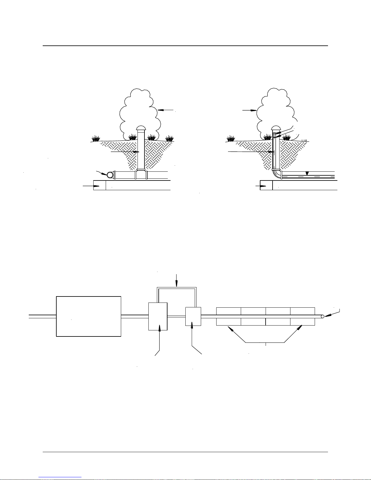
2.6.9 SYSTEM VENTING: It is recommended that all commercial systems be designed with vents.
Systems with high waste strength and systems with more than 46 cm of cover material as measured from
the top of the GSF modules to finished grade require venting. Designers that include vents in their
designs often specify the use of Granular Activated Carbon or Charcoal (GAC) filters to ensure that septic
odors do not become a nuisance. Designers should verify with the GAC filter manufacturer or supplier to
ensure that the filter will allow airflow from both directions of the filter. Otherwise the filter will block airflow
and the vent will not be effective in supplying enough oxygen that the system demands for long term
performance.
2.6.10 COMMERICAL SYSTEM PLANS REVIEW: BWD Engineering Inc. (604-789-2204), Eljen
Corporation’s Canadian Technical Representative, is available for a no cost review of any commercial
GSF plan prior to submission for approval from the local approving authority. Overall responsibility for
system design remains with the licensed designer and/or professional.

2016 British Columbia Design & Installation Manual 15 www.eljen.com
2.7 GSF Design Considerations for Replacing Failed Systems
Before designing a GSF system to replace a failed system, IDENTIFY THE CAUSE OF FAILURE and adjust
new system design accordingly. Listed below are some of the most common reasons why septic systems fail:
Leaky plumbing fixtures.
Pump settings incorrect or not working properly.
More occupants or bedrooms than system were designed for.
Unusually high water usage.
Garbage disposal.
Water softener backwash.
Detrimental chemicals being used.
Excessive grease in system.
Failed or missing septic tank outlet baffle.
Infiltration of ground water into a leaky septic tank or pump chamber.
Infiltration of surface water into the system.
Specified Sand that does not meet the requirements as outlined in this manual.
Poor quality fills material used below the system.
Poor quality backfill over system (no oxygen flow to system).
System too close to water table.
Mounding due to poor drainage or soil permeability.
Part or system not used because of blockage or excessive settling.
System is undersized.
Excessive backfill over system (more than 18” requires venting).
Crushed distribution pipe(s).
Distribution pipes not level.
Loam not removed prior to construction.
No vent installed or improper venting.
Clogged septic tank effluent filter.
No outlet baffle or tee in septic tank.
Septic Tank needs to be pumped.
Wiring or electrical problems with bump systems.
Supply line to septic tank or D-box needs repair.

2016 British Columbia Design & Installation Manual 16 www.eljen.com
2.8 Required Notes on Design Plans
1. This system (IS/IS NOT) designed for the use of a garbage disposal.
2. This system is NOT designed for backwash from a water softener.
3. This system IS design for __________ wastewater only.
4. Organic Loam Layer must be removed from bed and slope extension areas prior to fill placement.
Scarify subsoil prior to fill placement.
5. All fill material shall meet SPM requirements. The 15 cm of Specified System Sand underneath and
surrounding the GSF modules shall be washed concrete sand meeting the requirements of ASTM
C33 with less than 10% passing a #100 sieve and less than 5% passing a #200 sieve.
6. Backfill material can be native soil with no stones larger than 5 cm in any dimension to a maximum
depth of 30 cm over the GSF modules and covered with 10 cm to 15 cm of clean loam.
7. Any system that is more than 46 cm below finish grade as measured from the top of the module shall
be vented.
8. This design complies with and must be installed in accordance with the February 2016 Eljen GSF
Design and Installation Manual for British Columbia.
With the following exceptions: (List any exceptions here)

2016 British Columbia Design & Installation Manual 17 www.eljen.com
3.0 System Installation Guidelines
3.1 General System Installation Guidelines
Note: An installation video is available for viewing at www.eljen.com
1. Place the 18 cm tall Geotextile Filter Modules on top of a 15 cm minimum level surface of ASTM C33
Specified Sand with less than 10% passing #100 sieve and less than 5% passing #200 sieve. You must
use the Specified Sand as listed on page 6 of this manual to ensure proper system operation.
2. Specified Sand placed along both sides and across the top of the GSF module ensures aeration of the
modules. Additional sand placed above the module is recommended.
3. Use the provided clamps to secure the approved perforated 10 cm diameter distribution pipe to the top of
each GSF module.
4. In applications where modules are spaced out end-to-end to increase effective basal area all perforated
holes not discharging at least 15 cm onto a GSF module must be sealed. See Figure 9 for an example.
5. Cover the tops and sides of the modules along the entire length of each row with Eljen geotextile cover
fabric.
6. If modules are spaced end-to-end, fabric must be cut and allowed to drape over and protect the ends of
each spaced module. A continuous run of geotextile fabric is not allowed for these applications.
7. Where the percolation rate exceeds 30 minutes-per-inch or the soil texture is finer, the system should be
built from one end to the other to avoid any compaction of the soil by the excavator.
8. When backfilling the installation with native soil, stones 5 cm or larger must be removed.
9. Finish by grading the area to divert storm water runoff away from the system.
10. Do not drive backhoe wheels over GSF modules. Light-weight track rigs may cross system area
sparingly with a minimum of 30 cm of cover over the distribution pipe. System area should only be
crossed perpendicularly.
11. Do not drive over mound or elevated systems.
12. It is also permissible to back-blade the soil to set final minimum cover. Perimeter landscape timbers are
also recommended to locate the shallow beds, thereby keeping vehicles off the system.
13. Seeding and stabilizing the soil cover is required to protect the system from soil erosion.
14. Where the elevation of the surface exceeds the natural grade, a block or landscape timber frame or
sloping soil toe at a 3:1 grade can be used to help eliminate soil erosion and support maintenance of the
stabilizing grass cover adjacent to the GSF.
15. For pumped systems, provide a well-anchored D-box with a velocity reduction tee or baffle. Vent system
at far end of the trench or bed when more than 46 cm of cover material as measured from the top of the
GSF modules to finished grade is used.

2016 British Columbia Design & Installation Manual 18 www.eljen.com
3.2 Trench and In-Ground Bed System Installation Instructions
1. Carefully lay out the system components and boundaries. Define the location and elevation of the
trench or bed and distribution box based on the septic tank outlet elevation and pipe grades required
to maintain flow to each component.
2. Prepare the site according to BC regulations. Do not install a system on saturated ground or wet soils
that are smeared during excavation. Keep heavy machinery off clay soils used for the GSF system as
well as down-slope from the system where soil structure is critical for absorption and drainage of the
treated effluent.
3. Plan all drainage requirements above (up-slope) of the system as to not adversely affect systems
area. Set soil grades to ensure that storm water drainage and ground water is diverted away from the
absorption area once the system is complete.
4. Excavate the trench or bed. Scarify the receiving layer to maximize the interface between the native
soil and Specified Sand.
5. Minimize walking in the trench or bed prior to placement of the Specified Sand to avoid soil
compaction.
6. Place 15 cm layer of Specified Sand to 2.5 cm above the sand fill grade. Gently hand compact, level
and rake the Specified Sand on grade. A hand tamper is sufficient to stabilize the Specified Sand
below the GSF modules. The finished height below the GSF module must be 15 cm minimum. Check
the zero grades with a laser level before placing the GSF modules.
7. Place GSF modules with PAINTED STRIPE FACING UP, end to end on top of the Specified Sand.
8. Provide D-box(s) installed in accordance with the current Standard Practice Manual.
9. Use approved 10 cm non-perforated pipe from the distribution box to the GSF modules.
10. Center approved 10 cm perforated distribution pipe lengthwise over modules with orifices at 4:00 and
8:00.
11. In applications where modules are spaced end-to-end to increase effective basal area all perforated
holes not discharging at least 15 cm onto a GSF module must be sealed. See Figure 9 for an
example.
12. Secure pipe to GSF modules using one Eljen hoop per module. Push hoop ends straight down into
up-facing core, through the fabric and into the underlying sand.
13. Spread Eljen cover fabric lengthwise over the pipe and drape over the sides of the GFS module rows.
Secure in place with Specified Sand between and along the sides of the modules. Avoid blocking
holes in perforated pipe by placing the cover fabric over the pipe prior to placing fill over the modules.
Note: If modules are spaced end-to-end, fabric must be cut and allowed to drape over and protect the ends of
each spaced module. A continuous run of geotextile fabric is not allowed for these applications.
14. Place 15 cm minimum of Specified Sand along the sides of the modules and at the ends of each
module row.
15. Complete backfill with Sandy Loam to 20 cm minimum of the GSF modules. Backfill exceeding 46
cm requires venting at the far end of the trench. Fill should be clean, porous and devoid of large
rocks. Use well graded sandy loam fill. Do not use wheeled equipment over the system. A light track
machine may be used with caution, avoiding crushing or shifting of pipe assembly. Backfill in direction
of perforated pipe.
16. Divert surface runoff. Finish grade to prevent surface ponding. Seed loam, and protect from erosion.

2016 British Columbia Design & Installation Manual 19 www.eljen.com
3.3 Raised or Fill System Installation Instructions
Note: Refer to Figure 12 for Design Illustration.
1. Carefully lay out the system components and boundaries. Define the location and elevation of the
raised bed or fill system and distribution box based on the septic tank outlet elevation and pipe
grades required to maintain flow to each component.
2. Prepare the site according to BC regulations. Do not install a system on saturated ground or wet soils
that are smeared during excavation. Keep heavy machinery off clay soils used for the GSF system as
well as down-slope from the system where soil structure is critical for absorption and drainage of the
treated effluent.
3. Plan all drainage requirements above (up-slope) of the system as to not adversely affect systems
area. Set soil grades to ensure that storm water drainage and ground water is diverted away from the
absorption area once the system is complete.
4. Remove the Organic Layer. Scarify the receiving layer to maximize the interface between the native
soil and Specified Sand.
5. Minimize walking in the basal area prior to placement of the specified fill material to avoid soil
compaction.
6. Place fill material meeting SPM requirements onto the soil interface as you move down the excavated
area. If this is done in two steps, bring in the fill material from the up-slope side of the excavation.
Place 15 cm layer of Specified Sand to 2.5 cm above the sand fill grade. Gently hand compact, level
and rake the sand on grade.
7. A hand tamper is sufficient to stabilize the Specified Sand below the GSF modules. Check the zero
grade of the top of the Specified Sand using a 2 x 4 and carpenter’s level or a laser before placing the
modules.
8. Place GSF modules with PAINTED STRIPE FACING UP, end to end on top of the Specified Sand.
9. Use approved 10 cm non-perforated pipe from the distribution box to the GFS modules.
10. Center approved 10 cm perforated distribution pipe lengthwise over modules with orifices at 4:00 and
8:00.
11. Secure pipe to GSF modules using one Eljen hoop per module. Push hoop ends straight down into
up-facing core, through the fabric and into the underlying sand layer.
12. Spread Eljen cover fabric lengthwise over the pipe and drape over the sides of the GFS module rows.
Secure in place with Specified Sand between and along the sides of the modules. Avoid blocking
holes in perforated pipe by placing the cover fabric over the pipe prior to placing fill over the modules.
Note: If modules are spaced end-to-end, fabric must be cut and allowed to drape over and protect the ends of
each spaced module. A continuous run of geotextile fabric is not allowed for these applications.
13. Place 15 cm minimum of Specified Sand along the sides of the modules and at the ends of each
module row.
14. Complete backfill with Sandy loam to 20 cm minimum of the GSF modules. Backfill exceeding 46 cm
requires venting at the far end of the trench. Fill should be clean, porous and devoid of large rocks.
Use well graded sandy loam fill. Do not use wheeled equipment over the system. A light track
machine may be used with caution, avoiding crushing or shifting of pipe assembly. Backfill in direction
of perforated pipe. Divert surface runoff. Finish grade to prevent surface ponding. Seed loam, and
protect from erosion.

2016 British Columbia Design & Installation Manual 20 www.eljen.com
3.4 Serial Distribution on Sloped System Installation Instructions
1. Carefully lay out the system components and boundaries. Define the location and elevation of the serial
distribution system and distribution box based on the septic tank outlet elevation and pipe grades required
to maintain flow to each component.
2. Prepare the site according to BC regulations. Do not install a system on saturated ground or wet soils that
are smeared during excavation. Keep heavy machinery off clay soils used for the GSF system as well as
down-slope from the system where soil structure is critical for absorption and drainage of the treated
effluent.
3. Plan all drainage requirements above (up-slope) of the system as to not adversely affect systems area. Set
soil grades to ensure that storm water drainage and ground water is diverted away from the absorption
area once the system is complete.
4. Excavate the Trenches. Scarify receiving layer by raking or contour plowing at a right angle to slope before
placing the specified fill material or Specified Sand. Scarify the receiving layer to maximize the interface
between the native soil and Specified Sand.
5. Minimize walking in the excavated area prior to placement of the specified fill material to avoid soil
compaction.
6. Place fill material meeting SPM requirements onto the soil interface as you move down the excavated
area. If this is done in two steps, bring in the fill material from the up-slope side of the excavation. Place 15
cm layer of Specified Sand to 2.5 cm above the sand fill grade. Gently hand compact, level and rake the
sand on grade.
7. A hand tamper is sufficient to stabilize the Specified Sand below the GSF modules. Check the zero grade
of the top of the Specified Sand using a 2 x 4 and carpenter’s level or a laser before placing the modules.
8. Place GSF modules with PAINTED STRIPE FACING UP, end to end on top of the Specified Sand.
9. Drop Boxes are placed at the beginning of each row along the slope. Non-perforated pipe is plumbed to
the next lower trench. Flow Equalizer fittings may be used to further manage wastewater flow if specified
by the system designer.
10. Use approved 10 cm non-perforated pipe from the drop box to the GSF modules.
11. Install a line of approved 10 cm perforated distribution pipe lengthwise on the first row over the GSF
modules with orifices at 4:00 and 8:00. Cap at the far end.
12. In applications where modules are spaced end-to-end to increase effective basal area all perforated holes
not discharging at least 15 cm onto a GSF module must be sealed. See Figure 9 for an example.
13. Secure pipe to GSF modules using one Eljen hoop per module. Push hoop ends straight down into up-
facing core, through the fabric and into the underlying sand layer.
14. Spread Eljen cover fabric lengthwise over the pipe and drape over the sides of the GFS module rows.
Secure in place with Specified Sand between and along the sides of the modules. Avoid blocking holes in
perforated pipe by placing the cover fabric over the pipe prior to placing fill over the modules. Note: If
modules are spaced end-to-end, fabric must be cut and allowed to drape over and protect the ends of each
spaced module. A continuous run of geotextile fabric is not allowed for these applications.
15. Place 15 cm minimum of Specified Sand along the sides of the modules and at the ends of each module
row.
16. Complete backfill with sandy loam to 20 cm minimum of the GSF modules. Backfill exceeding 46 cm
requires venting at the far end of the trench. Fill should be clean, porous and devoid of large rocks. Use
well graded sandy loam fill. Do not use wheeled equipment over the system. A light track machine may be
used with caution, avoiding crushing or shifting of pipe assembly. Backfill in direction of perforated pipe.
17. Divert surface runoff. Finish grade to prevent surface ponding. Seed loam, and protect from erosion.
Other manuals for GSF
3
Table of contents
Other Eljen Water Filtration System manuals