Eljen GSF User manual

Geotextile Sand Filter
CORPORATION
Innovative Environmental Products & Solutions Since 1970

2013 Virginia Design & Installation Manual 2 www.eljen.com
Table of Contents
SUBJECT PAGE
Glossary of Terms 4
GSF System Description 6
1.0 Basic System Design 8
2.0 Systems for Level Sites 10
3.0 Systems for Sloped Sites 10
4.0 Pumped & Pressure Systems 10
5.0 General System Installation Guidelines 12
6.0 Required Notes on Design Plans 13
7.0 System Ventilation 14
8.0 Commercial Systems 15
9.0 Modified Trench Installations 16
10.0 Modified Trench Installations for Shallow Placement Systems 19
11.0 PAD Installations for Subsurface Installations 21
12.0 PAD Installations for Raised or Fill Systems 22
13.0 Slope System Installations for Modified Trenches & PADS 25
14.0 Modified Trench Design Guidance 27
15.0 Modified PAD Design Guidance 32
16.0 Troubleshooting GSF Systems 36
17.0 Design for Failed Systems 37
GSF DRAWINGS AND TABLES PAGE
Drawings
Fig. 1 Typical GSF Module Trench Cross Section 6
Fig. 2 GSF System Operation 7
Fig. 3 Example Pressure Distribution –Upward Facing Orifice Layout 11
Fig. 4 Example Pressure Pipe Design Layout 11
Fig. 5 Vent for Gravity and Pump Dosed PAD Systems 14
Fig. 6 GSF with Vent Extended to Location Behind Tree or Shrub 15
Fig. 7 Air By-Pass Line Plan View for Venting of Pumped Systems 15
Fig. 8 Air By-Pass Line Cross Section for Venting of Pumped Systems 16
Fig. 9 Multiple Trench Cross Section 18
Fig. 10 Multiple Trench Plan View 18
Fig. 11 Multiple Trench Pump Dosed Plan View 18
Fig. 12 Level Shallow Placement Trench System 20
Fig. 13 Sloping Shallow Placement Trench System 20
Fig. 14 In-Ground PAD System Cross Section 23
Fig. 15 Raised or Fill PAD System Cross Section 23
Fig. 16 Gravity PAD System Plan View 24
Fig. 17 Pump Dosed PAD System Plan View 24
Fig. 18 Sloped Modified Trench Cross Section 26
Fig. 19 Sloped PAD System Cross Section 26
Fig. 20 Modified Trench Option Cross Section 27

2013 Virginia Design & Installation Manual 3 www.eljen.com
Table of Contents
System Sampling Port Installation Drawings PAGE
Drawings
Fig. 21 - 33 40 - 46
System Sampling Procedure Drawings
Drawings
Fig. 34 - 36 47 - 48
Tables
Table 1 Specified Sand Sieve Requirements 5
Table 2 B43 Modified Gravity Trench Sizing 28
Table 3 B43 Modified Pressure System Trench Sizing 30
Table 4 B43 Gravity PAD Sizing 32
Table 5 B43 Pressure System PAD Sizing 34

2013 Virginia Design & Installation Manual 4 www.eljen.com
Glossary of Terms
B43 Module (L x W x H) 48” x 36” x 7”
Biofabric Special filter fabric within the Geotextile Sand Filter Modules upon which the primary biomat
layer forms.
Cover Fabric The geotextile cover fabric (provided by manufacturer) that is placed over the GSF modules.
Cuspated Core The rigid plastic core of the GSF module. It separates the geotextile fabric and creates
downward infiltration channels and upward aeration channels to provide primary filtration
and biological treatment of the septic effluent. The curvilinear shape of the cuspations
offers increased treatment surface area and greater effluent storage.
Design Flow The estimated peak flow that is used to size a GSF system is 150 gallons per day per
Bedroom.
Distribution Box Also known as a D-Box –is a plastic or concrete box that receives effluent from a septic
tank and splits the flow to pipes placed above the GSF modules. For equal distribution, the
outlet pipe orifices are typically set at the same elevation to equalize the flow to each line.
The distribution box method is only used when the receiving GSF modules are at the same
elevation.
Flow Dial Special insert placed in the end of distribution pipes within the distribution box to
compensate for possible unleveled installations and promote favorable flow to the
distribution pipes.
GSF The Eljen Geotextile Sand Filter modules and the Specified Sand layer along the base and
sides of the modules.
GSF Module The individual module of a GSF system. The module is comprised of a cuspated plastic core
and corrugated geotextile fabric.

2013 Virginia Design & Installation Manual 5 www.eljen.com
Glossary of Terms
Specified Sand To ensure proper system operation, the system must be installed using ASTM C33 sand
with less than 10% passing a #100 sieve and less than 5% passing a #200 sieve. Listed
below is a chart outlining the sieve requirements for the Specified Sand. Ask your material
supplier for a sieve analysis to verify that your material meets the required specifications.
Table 1: SPECIFIED SAND SIEVE REQUIREMENTS
STA Soil Treatment Area
STE Septic Tank Effluent (STE) is anaerobically digested effluent that is discharged to a
Geotextile Sand Filter module for further treatment.
Width & Length The system width is the sand dimension perpendicular to the GSF module rows. The
system length is measured parallel to the rows of GSF modules.
Wire Clamp Wire Clamps are used to secure perforated distribution pipe above the GSF modules.
ASTM C33
Sand Specification
Sieve Size
Sieve Square
Opening Size
Specification
Percent Passing
(Wet Sieve)
0.375"
9.5 mm
100.0 -100.0
#4
4.75 mm
95.0 - 100.0
#8
2.36 mm
80.0 - 100.0
#16
1.18 mm
50.0 - 85.0
#30
600 µm
25.0 - 60.0
#50
300 µm
5.0 - 30.0
#100
150 µm
< 10.0
#200
75 µm
< 5.0

2013 Virginia Design & Installation Manual 6 www.eljen.com
GSF System Description
This manual provides design and installation information for the Eljen GSF Geotextile Sand Filter system
utilizing the GSF B43 Module.
FIGURE 1: TYPICAL GSF B43 MODULE TRENCH CROSS SECTION
48" -72"
36"
6"-18" 6"-18"
SPECIFIEDSAND
GEOTEXTILEFABRIC
12" -18"OF
CLEANFILL
7"
12"
19"
< 18" - 12"
(Minimum 6" of Naturally Occuring Soil)
TL-2, TL-3
Minimum Vertical Separation
Requirements to Limiting Features
Vertical Seperation
from Bottom of Sand
Effluent Description
Septic, TL-2
≥ 18"
(Must Be Naturally Occurring Soil)
*Note: The minimum vertical separation distance to a limiting feature
must be maintained across the entire modified trench/pad area.
The GSF B43 module contains 7 Square feet of geotextile filter fabric per square foot, which equates to 86 square feet per
module.
Design layouts and installation instructions for sequential, equal or dosed distribution systems are included. Details on
unique design and construction procedures are also provided. To receive design standards for speciallyengineered dosing
systems or commercial systems, contact Eljen’s Technical Resource Department at 1-800-444-1359. GSF systems must
be designed and constructed according to this Design & Installation Manual and the State of Virginia Sewage Handling and
Disposal Regulations, including Chapter 613, Regulations for Alternative Onsite Sewage Systems (hereinafter the
Regulations).
The Eljen GSF system technology is based on research conducted by nationally recognized engineering scientists from the
University of Connecticut. Eljen Corporation has over 30 years of success in the onsite wastewater industry, with tens of
thousands of systems currently in use. The GSF is recognized by regulatory officials and experts in the industry as one of
the mostreliable wastewater treatment technologies in the marketplace today. The system specifications in this manual are
founded on this research and history.
The GSF technology is based on scientific principles which state that improved effluent quality provides increased soil
absorption rates. GSF’s proprietary two-stage Bio-Matt™ pre-filtration process improves effluent quality while increasing
reliability and ease of operation.
Third-party independent testing data based on NSF/ANSI Standard 40 Protocol has shown that the Eljen GSF
provides advanced treatment of septic tank effluent to better than secondary levels.

2013 Virginia Design & Installation Manual 7 www.eljen.com
GSF System Description
The Eljen GSF Geotextile Sand Filter system is a cost-effective upgrade from other septic technologies. Comprised of a
proprietary two-stage Bio-Matt™ pre-treatment process, the geotextile modules apply a better-than-secondary septic tank
effluent to the soil, increasing the soil’s ability to accept the effluent. The result is superior treatment in a smaller soil
absorption area.
How the GSF System Works
Primary Treatment Zone
▪Perforated pipe is centered above the GSF module to distribute septic effluent over and into corrugations
created bythe cuspated core of the geotextile module.
▪Septic effluent is filtered through the Bio-Matt fabric. The module’s unique design provides increased surface
area for biological treatment that greatly exceeds the module’s footprint.
▪Open air channels within the module support aerobic bacterial growth on the modules geotextile fabric
interface, surpassing the surface area required for traditional absorption systems.
▪An anti-siltation geotextile fabric covers the top and sides of the GSF module and protects the Specified
Sand and soil from clogging while maintaining effluent storage within the module.
Secondary Treatment Zone
▪Effluent slowly drips into the Specified Sand layer and supports unsaturated flow into the native soil. This
Specified Sand/soil interface maintains soil structure, thereby maximizing the available absorption interface in
the native soil. The Specified Sand supports nitrification of the effluent, which reduces oxygen demand in the
soil, thus minimizing soil clogging from anaerobic bacteria.
▪The Specified Sand layer also protects the soil from compaction and helps maintain cracks and crevices
in the soil. This preserves the soil’s natural infiltration capacity, which is especially important in finer
textured soils, where these large channels are critical for long-term performance.
▪Native soil provides final filtration and allows for groundwater recharge.
FIGURE 2: GSF SYSTEM OPERATION

2013 Virginia Design & Installation Manual 8 www.eljen.com
1.0 Basic System Design
1.1 TREATMENT FIELD SIZE: The sizing tables on pages 28 –34 apply to residential systems only. A minimum of
12 inches of separation is required between parallel rows of a GSF PAD system to utilize sidewall infiltration area.
Please contact Eljen’s Technical Resource Department at 1-800-444-1359 for design information on commercial
systems.
1.2 DEPTH TO GROUND WATER OR RESTRICTIVE LAYER: As required by state regulations; the bottom of the
GSF system requires a 12-inch minimum separation distance from the maximum seasonal high groundwater table.
Of the 12 inches required, 6 inches of soil must be naturally occurring. See Figure 1 of this manual for the separation
distances required based on effluent type. *Note: The minimum vertical separation distance to a limiting feature
must be maintained across the entire modified trench/pad area.
1.3 SPECIFIED SAND SPECIFICATION FOR MODIFIED TRENCH AND PAD SYSTEMS: The first 12 inches of
Specified Sand immediately under, between rows and around the perimeter of the GSF system must be an ASTM
C33 WASHED CONCRETE SAND WITH LESS THAN 10% PASSING A #100 SIEVE AND LESS THAN 5%
PASSING A #200 SIEVE. Please place a prominent note to this effect on each design drawing. See Table 1 for
more information on the ASTM C33 sand and sieve specifications.
1.4 FILL FOR RAISED SYSTEMS: Fill material below the 12-inch sand specified in Section 1.3 for raised PAD
systems must be clean fill material in accordance with State of Virginia requirements.
1.5 PLACING GSF MODULES: Each row of modules is laid level, end to end on the above Specified Sand. No
mechanical connection is required between modules.
1.6 DISTRIBUTION PIPE: SDR-35 or equivalent is required. Place SDR-35 perforated pipe on top of GSF modules
with holes a 5 and 7 o’clock. Secure pipe to GSF modules with provided wire clamps, one clamp per Eljen module.
1.7 DISTRIBUTION BOX: Set the gravity system D-box outlet invert a minimum of ⅛ inch drop in elevation per
linear foot to the top first module in the Modified Trench or PAD configuration. Set a 2-inch minimum drop for dosed
systems from the D-box to the modules. The fill below the distribution box and pipes feeding the system must be
compacted to prevent settling. Flow Dials may be used in either Gravity or Dosed installations.
1.8 COVER FABRIC: Geotextile cover fabric is provided by Eljen Corporation for all GSF systems. It is placed over
the top and sides of the module rows to prevent long term siltation and failure. Cover fabric substitution is not
allowed. Fabric should drape vertically over the pipe and must not block holes in the distribution pipe or be stretched
from the top of the pipe to the outside edge of the modules. “Tenting” will cause undue stress on fabric and pipe.
1.9 BACKFILL & FINISH GRADING: Complete backfill with 12-18 inches of clean porous fill measured from the top
of modules. Backfill exceeding 18 inches requires venting at the far end of the Modified Trench or PAD. Use well
graded sandy fill that is clean, porous and devoid of large rocks. Do not use wheeled equipment over the system.
A light track machine may be used with caution, avoiding crushing or shifting of pipe assembly. Divert surface runoff
from the Soil Treatment Area, (STA). Finish grade to prevent surface ponding. Seed and loam system area to
protect from erosion.
1.10 NUMBER OF GSF MODULES REQUIRED: Tables 2 - 5 indicate the minimum number of B43 GSF modules
required for various soil percolation rates and system configurations. Residential systems use a minimum of 5 B43
units per bedroom. Examples of the Modified Trench and PAD configuration are located in sections 15 and 16 of
this manual.
Note: The use of linear loading rates may affect the number of modules required for a particular design. Eljen
promotes the use of best engineering practices regarding linear loading rates when designing PAD systems on
sloped terrain. Longer thinner systems are recommended.

2013 Virginia Design & Installation Manual 9 www.eljen.com
1.0 Basic System Design
1.11 ADDITIONAL FACTORS EFFECTING RESIDENTIAL SYSTEM SIZE: Homes with expected higher than
normal water usage may consider increasing the septic tank volume as well as incorporating a multiple compartment
septic tank. Consideration for disposal area may be increased for expected higher than normal water use.
For example:
Luxury homes, homes with a Jacuzzi style tubs, and other high use fixtures.
Homes with known higher than normal occupancy.
Homes with water conditioner backwash (Diversion from septic tank required).
1.12 GARBAGE DISPOSALS: Garbage disposals should not be used with the GSF system. Design drawings shall
include a note “Garbage disposals shall not be used with this system”. However, if such units are proposed to
be used, other measures must be taken to prevent solids from leaving the tank and entering the system such as:
Increasing the septic tank capacity by a minimum of 30%, or
Installation of a second septic tank installed in series, or
Installation of an appropriate sized septic tank outlet effluent filter.
NOTE: Eljen requires the use of septic tank outlet effluent filters on all systems, especially on those systems that
have single compartment tanks and garbage disposal systems installed, even if the tanks design capacity has been
increased.
1.13 WATER SOFTENERS/CONDITIONERS: Water conditioners can adversely affect septic tank treatment and
add to hydraulic load of the system. Discharge of residential conditioner backwash from these devices shall be into
a separate alternative disposal system. This location should be far enough away from the STA as to not affect its
performance.
1.14 SYSTEM VENTING: All systems require sufficient oxygen supply to the STA to maintain proper long term
effluent treatment. Therefore, the following situations require venting at the distal end of the STA:
Any system with more than 18 inches of total cover measured from the top of the module.
Areas subject to compaction.
1.15 VEHICULAR TRAFFIC: All vehicular traffic is prohibited over the GSF system. This is due to the compaction
of material required to support traffic loading which greatly diminishes absorption below the STA; and the void space
that naturally exists in soils for oxygen transfer on top of the STA is reduced by compaction from vehicular traffic.
1.16 SEPTIC TANKS: Must conform to the minimum requirements of State and/or Local Regulations. Many
designers are now specifying 2-compartment septic tanks. Eljen supports this practice.
1.17 EFFLUENT FILTERS: Effluent filters are required as a means of preventing solids from leaving the tank.
1.18 RISERS: It is strongly recommended that risers be installed which will extend the septic tank lids to finish
grade. This will provide easy access to the septic tank for periodic maintenance such as pumping, inspection, and
filter maintenance. Please follow all State and Local Codes in regards to installation requirements for risers.
1.19 PUMP SYSTEM DESIGNS:
The Regulations do not specifically address pumps used for purposes other than conveying effluent to a
dispersal system. 12 VAC 5-610-880 is waived in its entirety for pumps, pump chambers, and
appurtenances integral to treatment systems.
Conveyance Pumps. The pump requirements contained in 12 VAC 5-610-880 subsections A.1, B.6, and B.7
are waived. Pump systems designed in accordance with these sections of the Regulations are not
appropriate for systems dispersing treated effluent to a reduced size absorption area.

2013 Virginia Design & Installation Manual 10 www.eljen.com
1.0 Basic System Design
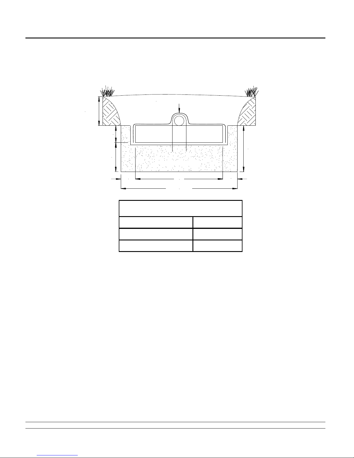
1.20 Separation Distances to Water Table: The separation distances between the infiltrative surface of a soil
absorption system and a water table is shown Figure 1 of this manual. *Note: The minimum vertical separation
distance to a limiting feature must be maintained across the entire modified trench/pad area.
1.21 Separation Distance to Impervious Strata for Shallow Placed Systems: The separation distance to an
impervious strata may be reduced from 18 inches to a distance not less than 12 inches below the Modified Trench or
PAD bottom when a professional engineer certifies in writing that they have evaluated the hydraulic capacity of the
site to disperse wastewater and that in their professional opinion, water mounding will not encroach on the
separation distance required as outlined in Figure 1 of this manual. *Note: The minimum vertical separation distance
to a limiting feature must be maintained across the entire modified trench/pad area.
1.22 Plans and Specifications: When plans conform to requirements of GMP #125, the requirements for formal
plans and specification required in 12 VAC 5-610-250.C is waived. Typical treatment system drawings and
specifications are shown at the end of this manual. When used in conjunction with a permit sketch, site specific
specifications, and manufacturer installation criteria, these documents will normally be sufficient to assure a system
can be properly installed. In some instances where a complex system is encountered, formal plans and
specifications may be required. This determination is left to the discretion of the District Health Department.
2.0 Systems for Level Sites
2.1 SYSTEM CONFIGURATIONS: Design level in-ground or raised PAD systems with 12-inch minimum spacing
between module rows. For Modified Trenches, center-to-center spacing must be no less than three times the width
of the trench for slopes up to 10%. For slopes over 10%, add one extra foot of separation for every 10% increase in
slope. The Specified Sand, Modified Trench, PAD, GSF modules, and distribution pipes are installed level at their
design elevations.
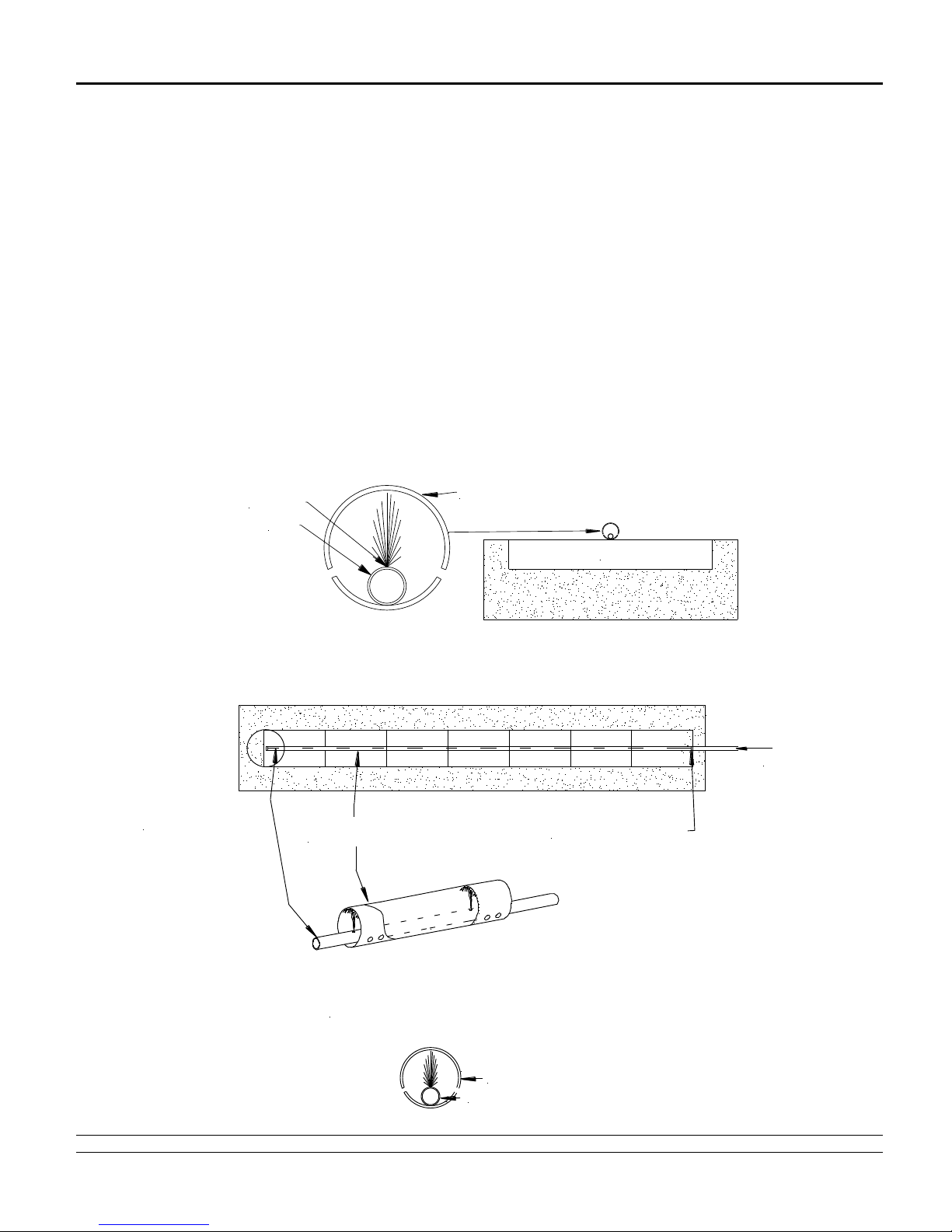
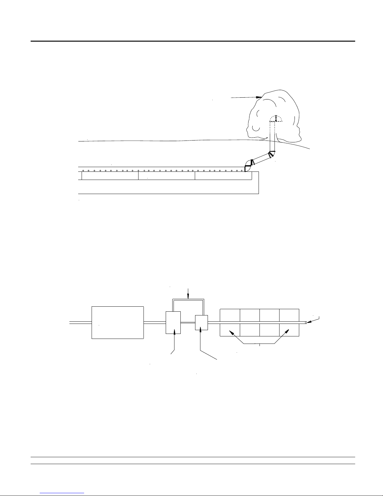
2.2 DISTRIBUTION PIPE LAYOUT: Perforated SDR-35 pipe or equivalent runs along the center of the modules for
both Modified Trench and PAD configurations. Ends for PAD systems should be connected with non-perforated pipe
at the distal end of the system as shown in Figure 5. For PAD systems over 40 feet in length, a non-perforated
“cross-over” connection should be installed perpendicular to the length of the STA connecting all distribution pipes at
the midway point of the system.
3.0 Systems for Sloped Sites
3.1 ROW SPACING: For PAD Systems, center-to-center and center-to-edge spacing will vary per design. For
slopes up to 15% a minimum of 1 foot edge to edge module spacing is required. For slopes over 15% a minimum 2
foot edge to edge module spacing is required. The edge of module to toe of downhill slope spacing is based on the
Regulations or a minimum 3:1 slope requirement.
For Modified Trenches, center-to-center spacing must be no less than three times the width of the trench for slopes
up to 10%. For slopes over 10%, add one extra foot of separation for every 10% increase in slope.
Note: For proposed PAD sites with slopes greater than 25% - Professional Engineer consultation is recommended.
3.2 DISTRIBUTION BOX: Provide a D-box at the beginning of the first row of modules for effluent distribution and
velocity reduction and as a system inspection port. All rows must be fed evenly.
4.0 Pumped & Pressure Systems
4.1 PUMP DISTRIBUTION BOX: Specify an oversized distribution box for pumped systems. Provide velocity
reduction in the D-box with a tee or baffle. Set D-box invert 2 inches higher than invert of perforated pipe over GSF
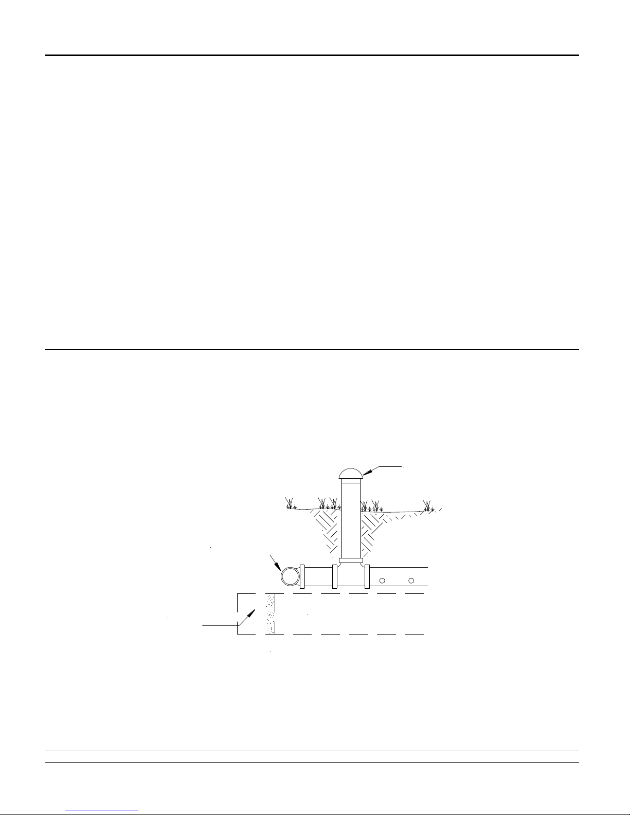
modules. If the absorption area is installed deeper than 18 inches, the system must be vented. See section 5.0 of
this manual for detailed information on venting of systems.

2013 Virginia Design & Installation Manual 11 www.eljen.com
4.0 Pumped & Pressure Systems
4.2 DOSING DESIGN CRITERIA: Dosing volume must be set to deliver a maximum of 4 gallons per B43 module
per dosing cycle with low head high volume pumps preferred. Higher flow rates and short dose cycle push the
effluent down the line and thus disperse the effluent over a larger area. A valve on the force main is recommended to
set the flow rate so that the orifices on the outlet pipes are submerged and the d-box does not overflow. Adjustment
of the flow rate is likely needed if a row of modules are rested thus changing the number or outlets. Fewer outlets in
the d-box force more effluent down each line and improve linear loading. Head loss and drain back volume must be
considered in choosing the pump size and force main diameter.
4.3 LOW PRESSURE DISTRIBUTION: Per 12 VAC 5-610-940 (c) (1), Pressure percolation lines should have a
minimum 1 1/4 inch inside diameter. Orifices should be designed at 3/16 inch to 1/4 inch in diameter and at pre-
determined intervals per design and code. Design requirements will vary depending on length of system and dose
volume. At least one drain hole per line at the 6 o’clock position must added to each line. Eljen recommends that
timed pressure distribution systems be designed by a professional engineer or other qualified person. See Figures 3
and 4 for example Low Pressure Distribution drawing details.
Flushing ports are required at the distal end of all pressure distribution networks. Flushing valves and vents can be
consolidated in larger systems by using valves on the outlet manifold.
FIGURE 3: EXAMPLE PRESSURE DISTRIBUTION –UPWARD FACING ORIFICE LAYOUT
B43
4" PVCPIPE - HOLESAT 5& 7 O'CLOCK
LPP
ORIFICE
FIGURE 4: EXAMPLE PRESSURE PIPE DESIGN LAYOUT
FROM
PUMPCHAMBER
LOWPRESSUREPIPE
(LPP) CAP END OF 4" PIPE
4" DIAMETER
PERFORATED PIPE
4" DIAMETERPERFORATEDPIPE
LOWPRESSURE PIPE(SIZEPER DESIGN)
PRESSUREPIPECROSSSECTIONFORALLAPPLICATIONS

2013 Virginia Design & Installation Manual 12 www.eljen.com
5.0 General System Installation Guidelines
1. All GSF systems are installed onto a 12-inch layer of Specified ASTM C33 Sand. Specified Sand is compacted in two
6-inch lifts.
2. Place the 7-inch tall GSF modules on top of a 12-inch minimum level surface of ASTM C33 Specified Sand with less
than 10% passing a #100 sieve and less than 5% passing a #200 sieve. You must use the Specified Sand as
listed in Table 1 of this manual to ensure proper system operation.
3. The GSF modules are placed with the WHITE PAINTED STRIPE FACING UP, end to end on top of the Specified
Sand.
4. Use the provided wire clamps to secure the approved perforated 4-inch diameter distribution pipe, SDR-35 or
equivalent, to the top of each GSF module.
5. Installation of the manufacturer supplied cover fabric. Cover fabric placement requires setting the tension and
orientation of the fabric around the sides of the perforated pipe on top of the GSF modules. If the fabric is too
loose, it blocks the effluent from draining into the modules. If the fabric is too tight, it could tear if punctured by a
sharp object and allow soil and sand to fall into the open corrugations of the modules. The correct tension of the
cover fabric is set by:
Spreading the cover fabric over the top of the module and down both sides of the module with the cover
fabric tented over the top of the perforated distribution pipe.
With a shovel, place small piles of Specified Sand directly over the pipe area allowing the cover fabric to
form a mostly vertical orientation along the sides of the pipe. Repeat this step moving down the pipe.
Anchor the cover fabric by placing Specified Sand along the sides and up to the top of the module and walk it in to
ensure the cover fabric is secure in place.
6. PAD system requires Specified Sand placed between module rows at various center-to-center distances. Percolation
rate, application rate and number of bedrooms have a direct effect with regards to center-to-center spacing. Table 4 &
5 provides values to calculate width and length of the PAD. Sizing examples can be found on pages 32 & 34.
7. Modified Trench Systems require a set amount of Specified Sand at the sides of all modules and 6 inches at each end
of the Modified Trench; see Table 2 or 3 for specific trench width requirements.
8. When backfilling the installation with native soil, it is required that the backfill material is a well graded sandy fill; clean,
porous, and devoid of rocks.
9. Finish bygrading the area to divert storm water runoff awayfrom the system.
10. Driving or paving over the Geotextile Sand Filter area is prohibited. For shallow installations, light-weight track-
mounted machines are best for setting the final grade. It is also permissible to back-blade the soil to set final minimum
cover. Landscape stakes are helpful to outline the construction area while backfilling the system.
11. Seeding and stabilizing the soil cover is required to protect the system from soil erosion.
12. Where the elevation of the surface exceeds the natural grade, a block or landscape timber frame or sloping soil toe at
a 3:1 grade can be used to help eliminate soil erosion and support maintenance of the stabilizing grass cover adjacent
to the GSF System.
13. Provide a well-anchored D-box on a stable, level and compacted gravel or sand base. A d-box with a velocity
reduction tee or baffle is required for pumped systems.
14. For pumped or pressurized systems, an additional 2-inch minimum airline must be extended from the d-box back to a
knockout or riser on the septic tank or pump chamber. This maintains the continuity of airflow from the field into the
house plumbing. Systems must also be vented at the distal end of the Modified Trench or PAD when there is
more than 18 inches of cover material as measured from the top of the module.

2013 Virginia Design & Installation Manual 13 www.eljen.com
6.0 Required Notes on Design Plans
1. This system (is/is not) designed for the use of a garbage disposal.
2. This system is not designed for backwash from a water softener.
3. Organic Loam Layer must be removed from PAD and slope extension areas prior to fill placement. Scarify
subsoil prior to fill placement.
4. Fill material shall meet or exceed the Eljen GSF Design & Installation Manual requirements. All fill material shall
be clean sand, free of topsoil, directly beneath the STA.
5. The 6, 12, or 18 inches surrounding and the 12 inches below the GSF modules shall be washed concrete sand
meeting the requirements of ASTM C33 with less than 10% passing a #100 sieve and less than 5% passing a
#200 sieve.
6. Backfill and Finish Grading: Carefully place backfill over the modules, followed by a total minimum depth of 12 - 18
inches of well graded sandy fill; clean, porous, and devoid of rocks, as measured from the top of the modules. Finish
grade must divert surface runoff from the STA and prevent surface ponding. Protect the system area from erosion by
loaming and seeding or by using other approved methods of erosion control.
7. Systems with total cover that exceeds 18 inches as measured from the top of the module shall be vented at the
far end of the system.
8. This design complies with and must be installed in accordance with the most current Eljen Design and
Installation Manual.

2013 Virginia Design & Installation Manual 14 www.eljen.com
7.0 System Ventilation
Air vents are required on all absorption systems located under impervious surfaces or systems with more than 18
inches of cover material as measured from the top of the GSF module to finished grade. This will ensure proper
aeration of the modules and sand filter. The GSF PAD has aeration channels between the rows of GSF modules
connecting to cuspations within the GSF modules. Under normal operating conditions, only a fraction of the filter is
in use. The unused channels remain open for intermittent peak flows and the transfer of air. The extension of the
distribution pipe to the vent provides adequate delivery of air into the GSF system, as shown in Figure 6.
Home plumbing operates under negative pressure due to hot water heating the pipes and reducing the density of air
in the house vent. As hot air rises and exits the home, it must be replaced by air from the GSF. To maintain this
airflow and fully aerate the GSF system, it is important that air vents are located only on the distal end of the GSF
pipe network.
If a pressure or pump dosed system is specified with greater than 18 inches of cover, an additional 2-inch minimum
airline must be extended from the GSF D-box back to a knockout or riser on the septic tank or pump chamber. This
maintains the continuity of airflow from the field into the house plumbing.
In a gravity fed GSF system, the vent is usually a 4-inch diameter pipe extended to a convenient location behind
shrubs, as shown in Figure 6. Corrugated pipe can be used with the placement and grade such that any
condensation that may accumulate in the pipe does not fill and thus close off this line. If the vent is extended, the
pipe must not drain effluent and must have an invert higher than the system.
System Ventilation Example Drawings
FIGURE 5: VENT FOR GRAVITY AND PUMP DOSED PAD SYSTEMS
ASTMC33
SPECIFIED
SANDAT
END OF
PAD
LOOPEDPADSYSTEM
NON-PERFORATED
LOOPPIPE
EDGEOF LASTMODULE
ATEND OF PAD
VENTEDCAP
VENTINGFORLOOPEDPADINSTALLATIONS
GRAVITYORDEMANDDOSEDSYSTEMS

2013 Virginia Design & Installation Manual 15 www.eljen.com
System Ventilation Example Drawings
FIGURE 6: GSF WITH 4” VENT EXTENDED TO CONVENIENT LOCATION BEHIND A TREE OR SHRUB
GSFMODULES
MOUNDEDBACKFILLOVERMODULES
COVER FABRICNOT SHOWNOVERDISTRIBUTION PIPEAND MODULES
CLEANBACKFILL FINISHEDGRADE
SHRUB
FIGURE 7: AIR BY-PASS LINE PLAN VIEW FOR VENTING OF PUMPED SYSTEMS
DESIGNED WITH GREATER THAN 18 INCHES OF COVER
SEPTICTANK
PUMP
CHAMBER DISTRIBUTION
BOX
GSFMODULES
VENT
BY-PASSLINE

2013 Virginia Design & Installation Manual 16 www.eljen.com
System Ventilation Example Drawings
FIGURE 8: AIR BY-PASS LINE CROSS SECTION FOR VENTING OF PUMPED SYSTEM
DESIGNED WITH GREATER THAN 18 INCHES OF COVER
PUMPTANK RISER
INLETPIPE
FROMSEPTIC
TANK
LPP PUMPLINE DISTRIBUTION
BOX
OUTLETPIPETO GSF
MODULEROW
MINIMUM2"
DIAMETER
BY-PASSAIR
LINE
8.0 Commercial Systems
Commercial systems require different sizing and design criteria as compared to residential systems. This manual is
intended for residential design only. Please contact Eljen’s Technical Resource Department at 1-800-444-1359 for
more information on commercial systems.

2013 Virginia Design & Installation Manual 17 www.eljen.com
9.0 Modified Trench Installations
1. Determine type and number of modules, length and width of the Modified Trench from Sizing Table 2 or 3.
2. Carefully lay out the system components and boundaries. Define the location and elevation of the Modified
Trench and distribution box based on the septic tank outlet elevation and pipe grades required to maintain flow
to each component.
3. Prepare the site. Do not install a system on saturated ground or wet soils that are smeared during excavation.
Keep heavy machinery off clayey soils used for the GSF system as well as down-slope from the system where
soil structure is critical for absorption and drainage of the treated effluent.
4. Plan all drainage requirements above (up-slope) of the system. Set soil grades to ensure that storm water
drainage and ground water is diverted away from the absorption area once the system is complete.
5. Excavate the Modified Trench. Scarify the receiving layer to maximize the interface between the native soil and
Specified Sand.
6. Minimize walking in the Modified Trench prior to placement of the Specified Sand to avoid soil compaction.
7. Place Specified Sand (see Table 1 for Specified Sand requirements) in two 6-inch lifts, compact each lift at a
time. The compacted Specified Sand height below the GSF module must be a minimum of 12 inches.
8. A hand tamper or vibratory compactor is sufficient to stabilize the Specified Sand below the GSF modules.
Check the zero grade of the top of the Specified Sand using a flat piece of lumber and a carpenter’s level
and/or a laser before placing the modules.
9. Place GSF modules with WHITE PAINTED STRIPE FACING UP, end to end on top of the Specified Sand.
10. Provide D-box(s) installed in accordance with this manual and current Virginia Sewage Handling and Disposal
Regulations.
11. Use 4-inch SDR-35 or equivalent non-perforated pipe from the distribution box to the GFS modules.
Recommended drop for gravity systems from D-Box to modules is 1/8 inch per linear foot.
12. Center 4-inch SDR-35 or equivalent perforated distribution pipe lengthwise over modules with orifices at 5 and
7 o’clock on level trench systems.
13. Secure pipe to GSF modules using one Eljen wire clamp per module. Push wire clamp ends straight down into
up-facing core, through the fabric and into the underlying Specified Sand.
14. Install the manufacturer supplied cover fabric. Cover fabric placement requires setting the tension and
orientation of the fabric around the sides of the perforated pipe on top of the GSF modules. The correct tension
of the cover fabric is set by; spreading the cover fabric over the top of the module and down both sides of the
module with the cover fabric tented over the top of the perforated distribution pipe. With a shovel, place small
piles of Specified Sand directly over the pipe area allowing the cover fabric to form a mostly vertical orientation
along the sides of the pipe. Repeat this step moving down the pipe. Anchor the cover fabric by placing
Specified Sand along the sides and up to the top of the module and walk it in to ensure the cover fabric is
secure in place.
15. Place 6 inches, 12 inches or 18 inches of Specified Sand along both sides of the modules and 6 inches at the
beginning and end of each Modified Trench. See Table 2 or 3 for the amount of Specified Sand required at the
sides of modules for your specific design and application rate.
16. Carefully place backfill over the modules, followed by loam to complete a total minimum depth of 12 - 18 inches
as measured from the top of the module. Systems with total cover that exceeds 18 inches as measured from
the top of the module shall be vented at the distal end of the system. Backfill material shall be a well graded
sandy fill; clean, porous, and devoid of rocks.
17. Divert surface runoff. Finish grade to prevent surface ponding. Seed, loam, and protect from erosion.

2013 Virginia Design & Installation Manual 18 www.eljen.com
Modified Trench Installation Example Drawings
FIGURE 9: MULTIPLE TRENCH CROSS SECTIONS
SPECIFIEDSAND
NATIVE
SOIL
12"
NATIVE SOIL
12 - 18" OF
CLEAN FILL 12 - 18" OF
CLEAN FILL
SPECIFIEDSAND 19"
12' UPTO10%SLOPE+ 1' FOREACHINCREASE OF 10%
36"
FIGURE 10: MULTIPLE TRENCH PLAN VIEW
NATIVE SOIL SPECIFIED SAND
DISTRIBUTION
BOX
PERDESIGN
PERDESIGN
FIGURE 11: MULTIPLE TRENCH PUMP DOSED PLAN VIEW
PERDESIGN
PERDESIGN
DISTRIBUTION
BOX
SPECIFIEDSAND
NATIVE SOIL
SEPTIC
TANK
PUMP
TANK
PUMPLINE

2013 Virginia Design & Installation Manual 19 www.eljen.com
10.0 Modified Trench Installations for Shallow Placement Systems
1. Determine the module type, length and width of the Modified Trench from Sizing Table 2 or 3. Modified Trenches
use center to center spacing consistent with the Regulations. Please see Table 2 or Table 3 for the amount of
Specified Sand required for the appropriate sf/module rate chosen.
2. Carefully lay out the system components and boundaries. Define the location and elevation of the Shallow
Placement Modified Trench system and distribution box based on the septic tank outlet elevation and pipe
grades required to maintain flow to each component.
3. Prepare the site. Do not install a system on saturated ground or wet soils that are smeared during excavation.
Keep heavy machinery off clayey soils used for the GSF system as well as down-slope from the system where
soil structure is critical for absorption and drainage of the treated effluent.
4. Plan all drainage requirements above (up-slope) of the system. Set soil grades to ensure that storm water
drainage and ground water is diverted away from the absorption area once the system is complete.
5. Excavate the Shallow Placement Modified Trench area. Key in and scarify the receiving layer to maximize the
interface between the native soil and Specified Sand material.
6. Minimize walking in the excavated area prior to placement of the specified fill material to avoid soil compaction.
7. Place fill material meeting State/County requirements onto the native soil interface.
8. Compact Specified Sand (see Table 1 of the manual for Specified Sand requirements) below the GSF modules
in two 6-inch lifts with a light tracked machine or compactor to a total height of 12 inches minimum.
9. A hand tamper or vibratory compactor is sufficient to stabilize the sand below the GSF modules. Check the zero
grade of the top of the sand using a flat piece of lumber and a carpenter’s level and/or a laser level before
placing the modules.
10. Place GSF modules with WHITE PAINTED STRIPE FACING UP, end to end on top of the Specified Sand.
11. Provide d-box(s) installed in accordance with this manual and current Virginia Sewage Handling and Disposal
Regulations.
12. Use 4-inch SDR-35 non-perforated pipe or equivalent non-perforated pipe from the distribution box to the GFS
modules. Recommended drop for gravity systems from D-Box to modules is 1/8 inch per linear foot to the GFS
modules.
13. Center 4-inch SDR-35 perforated distribution pipe or equivalent lengthwise over modules with orifices at 5 and 7
o’clock.
14. Secure pipe to GSF modules using one Eljen supplied wire clamp per module. Push wire clamp ends straight
down into up-facing core, through the fabric and into the underlying sand.
15. Spread the cover fabric over the top of the module and down both sides of the module with the cover fabric
tented over the top of the perforated distribution pipe. With a shovel, place small piles of Specified Sand directly
over the pipe area allowing the cover fabric to form a mostly vertical orientation along the sides of the pipe.
Repeat this step moving down the pipe. Anchor the cover fabric by placing Specified Sand along the sides and
up to the top of the module and walk it in to ensure the cover fabric is secure in place.
16. Place the required amount of Specified Sand along the sides of the module rows and at the beginning and end
of the Shallow Placement Modified Trench system. For sections of Specified Sand above existing grade, install
at a 3:1 slope.
17. Carefully place backfill over the modules, followed by loam to complete a total minimum depth of 12 - 18 inches
as measured from the top of the module. Sides/Slopes of capping material must be installed at a minimum of
3:1. Systems with total cover that exceeds 18 inches as measured from the top of the module shall be vented at
the distal end of the system. Backfill material shall be a well graded sandy fill; clean, porous, and devoid of
rocks.
18. Divert surface runoff. Finish grade to prevent surface ponding. Seed, loam and protect from erosion.

2013 Virginia Design & Installation Manual 20 www.eljen.com
Modified Trench for Shallow Placement Systems Example Drawings
FIGURE 12: LEVEL SHALLOW PLACEMENT TRENCH SYSTEM
SPECIFIED SAND
12"
12- 18" OF CLEANFILL
SPECIFIED SAND
12' UPTO 10%SLOPE + 1' FOR EACH INCREASE OF 10%
PERDESIGN
EXISTING GRADE KEYINTOEXISTING GRADE
3131
FIGURE 13: SLOPING SHALLOW PLACEMENT TRENCH SYSTEM
12"
12 - 18" OF CLEANFILL
SPECIFIEDSAND
12' UPTO 10%SLOPE +1' FOREACH INCREASE OF10%
PERDESIGN
EXISTINGGRADE
KEYINTOEXISTING GRADE
31
31
SPECIFIEDSAND
Other manuals for GSF
3
Table of contents
Other Eljen Water Filtration System manuals
Popular Water Filtration System manuals by other brands

Crystal Mountain
Crystal Mountain FIL-W300005 installation instructions

Vestergaard
Vestergaard LifeStraw PEAK Series user manual

Diamond H2O
Diamond H2O DCS6-45-100 product manual

Trox Technik
Trox Technik PFG Series Installation and maintenance manual

Pall
Pall Profile Operating and Installation Procedures

sterling water treatment
sterling water treatment UN Series Installation instructions & owner's manual