Eljen GSF User manual

Geotextile Sand Filter
CORPORATION
Innovative Environmental Products & Solutions Since 1970
New York
Design & Installation Manual
May 2017
www.eljen.com

2014 New York GSF Design & Installation Manual 2 www.eljen.com
Table of Contents
Subject Page
Terms and Definitions 3
GSF System Description 6
1.0 Basic System Design 7
2.0 Trench Configuration Sizing 10
3.0 Bed Configuration Sizing 13
4.0 Repair and Replacement System Sizing 16
5.0 GSF Sand Filter Design 20
6.0 Systems Designed for Level Sites 22
7.0 Systems Designed for Sloped Sites 23
8.0 Dosed or Pumped Systems 24
9.0 System Venting 25
10.0 Required Notes on Design Plans 26
11.0 System Installation Guidelines 27
12.0 Design for Replacement Systems 34
13.0 Trouble Shooting GSF Installation 35
Tables Page
Table 1: B43 GSF Residential Trench Sizing Table – Linear Feet Per System 10
Table 2: B43 GSF Residential Trench Sizing Table – Modules Per System 10
Table 3: B43 GSF Residential Bed Sizing Table – Square Feet Absorption Area Per System 13
Table 4: B43 GSF Residential Bed Sizing Table – Modules Per System 13
Table 5: B43 GSF Repair & Replacement Bed Sizing Table – Square Feet Per System 17
Table 6: B43 GSF Repair & Replacement Bed Sizing Table – Modules Per System 17
Table 7: B43 GSF Sand Filter Sizing Using Gravel Based Design 20
Drawings Page
Figure 1: GSF System Operation 6
Figure 2: Example Sizing of a Trench System 12
Figure 3: Example Sizing of a Bed System 15
Figure 4: Example Sizing of a Repair & Replacement Bed System 19
Figure 5: Example GSF Sand Filter Cross Section 21
Figure 6: Example GSF Sand Filter Plan View 21
Figure 7: Vertical Separation to Limiting Conditions 36
Figure 8: B43 GSF Trench Cross Section 36
Figure 9: Multiple Trench Cross Section 37
Figure 10: Shallow Trench Cross Section 37
Figure 11: Simple Trench with Center Loading Distribution Box 38
Figure 12: Trench Configuration for a Sloping Site / Avoiding Rock Out Crops and Trees 38
Figure 13: Drop Box Outlet Setup 39
Figure 14: Equal Loading Outlet Setup in a Dosed Distribution Box 40
Figure 15: B43 GSF Level Absorption Bed Installation Cross Section 41
Figure 16: B43 GSF Typical Level Absorption Bed Design Plan View 41
Figure 17: Air By-Pass Line Plan View for Venting of Pumped Systems 42
Figure 18: Air By-Pass Line Cross Section for Venting of Pumped Systems 42
Figure 19: Vent Detail for Gravity and Demand Dosed Distribution Systems 43
Figure 20: Vent Detail for Looped Bed Systems 43

2014 New York GSF Design & Installation Manual 3 www.eljen.com
Terms and Definitions
Appendix 75-A This appendix represents the minimum design standards for onsite wastewater
treatment systems serving residential properties and receiving sewage without
the admixture of industrial wastes or other wastes as defined in Environmental
Conservation Law, Section 17-0701, in quantities of less than 1,000 gallon per
day (gpd) in the State of New York.
Absorption Field
Area The area to which wastewater is distributed over the GSF modules for infiltration
into the soil.
B43 The GSF module model which measures 36” W x 48” L x 7” H in size.
Bio-Matt™ Fabric Special filter fabric within the Geotextile Sand Filter Modules upon which the
primary biomat layer forms as shown in Figure 1.
Cover Fabric The anti-siltation geotextile cover fabric provided by the manufacturer that is
placed over the GSF modules to keep out soil while allowing the exchange of
gases and moisture as shown in Figure 1.
Cuspated Core The rigid plastic core of a GSF module. It separates the geotextile fabric and
creates downward infiltration channels and upward aeration channels to provide
primary filtration and biological treatment of the septic effluent. The curvilinear
shape of the cuspations offers increased treatment surface area and greater
effluent storage.
Design Flow The estimated daily flow that is used to size a GSF system is defined in Appendix
75-A.3, Table 1, ranging from 110 gallons per bedroom to 150 gallons per
bedroom depending on use of water conserving fixtures. Individual Counties may
have their own flow requirements.
Distribution Box (Or D-Box) a plastic, fiberglass or concrete box that receives effluent from a
septic tank and splits the flow to pipes placed above the GSF modules. For equal
distribution, the outlet pipe orifices are typically set at the same elevation to
equalize the flow to each line. The distribution box method is only used when the
receiving GSF modules are at the same elevation. See Appendix 75-A.7 for
additional state required guidelines.
Drop Box A plastic, fiberglass or concrete box that is used on sloped systems where the
elevation of the incoming line is higher than that of the outgoing distribution and
outgoing spillover lines. This allows the loading of upper most trenches/rows in
the system prior to loading lower trenches/rows.
EHGWT The Estimated High Ground Water Table is the elevation of saturated condition
as measured or as estimated from evaluation of soil color and soil redoximorphic
features.
Flow Equalizer Special devices placed in the discharge side of distribution pipes on the
distribution box to minimize effects of settling and out of level installation. Other
similar devices include Speed Levelers and Dial-A-Flow that permit the
adjustment in the invert (outlet) elevation in each distribution pipe.
GSF The Eljen Geotextile Sand Filter modules and the 6-inch Specified Sand layer
along the base and sides of the modules.
GSF Module The individual module of a GSF system. The module is comprised of a cuspated
plastic core and corrugated geotextile fabric.
LTAR Long Term Acceptance Rate (LTAR) is the average equilibrium absorption rate
for effluent in a system, usually expressed in gallons per day per square foot. It
should not be confused with the design loading rate specified in Table 4B for
Trenches and Table 5 for absorption beds as defined in Appendix 75-A.
2014 New York GSF Design & Installation Manual 4 www.eljen.com
Terms and Definitions
Serial Distribution Designs common to sloping sites where GSF lines that are laid on contour and
receive effluent from a series of drop boxes at different elevations. Effluent floods
up-slope lines and then spills excess effluent to down-slope lines. Non-perforated
pipe placed on undisturbed soil connects successive down-slope trenches. See
Appendix 75-A.7.2 and Figure 12 of this manual for drop box layout for sloping
sites in this manual. Eljen recommends serial distribution utilizing drop boxes on
sloped sites.
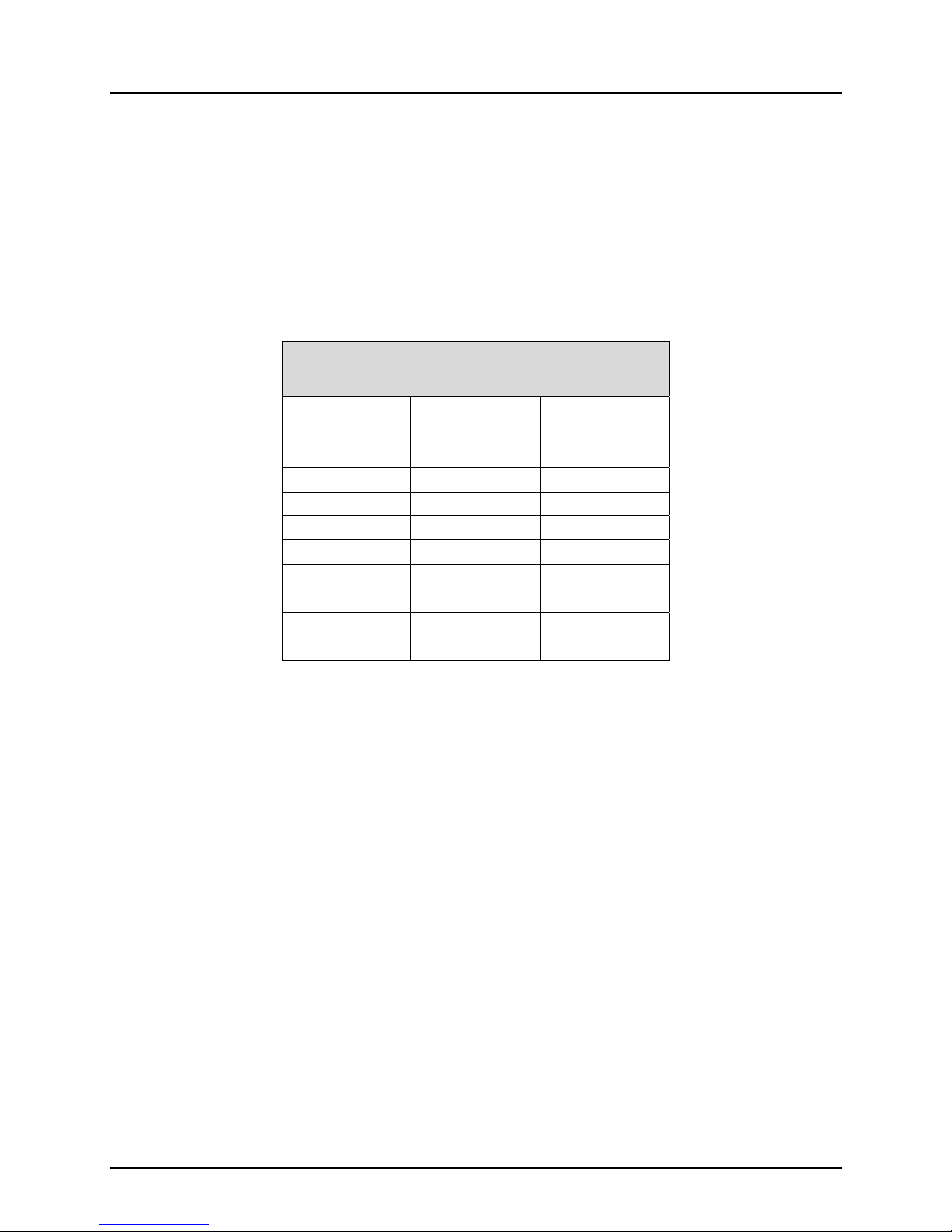
Specified Sand To ensure proper system operation, the system must be installed using ASTM
C33 sand with less than 10% passing #100 sieve and less than 5% passing #200
sieve. Listed below is a chart outlining the sieve requirements for the Specified
Sand as required by Eljen.
ASTMC33
SandSpecification
SieveSize
Sieve
SquareOpening
Size
Specification
PercentPassing
(WetSieve)
0.375" 9.5mm 100.0‐100.0
#4 4.75mm 95.0‐100.0
#8 2.36mm 80.0‐100.0
#16 1.18mm 50.0‐85.0
#30 600µm 25.0‐60.0
#50 300µm 5.0‐30.0
#100 150µm <10.0
#200 75µm <5.0
STE Septic Tank Effluent (STE) is anaerobically digested effluent that is discharged to
a Geotextile Sand Filter module for further treatment.
Width & Length The system width is the sand dimension perpendicular to the GSF module rows.
The system length is measured parallel to the rows of GSF modules.
Wire Clamps Clamps used to secure perforated pipe above the GSF modules.

2014 New York GSF Design & Installation Manual 5 www.eljen.com
Introduction
This manual provides design and installation information for the Eljen GSF Geotextile Sand Filter system
using the B43 GSF module. Typical design layouts and installation instructions are included in this manual.
GSF systems must be designed and constructed according to the current edition of the New York
Department of Health Appendix 75-A Wastewater Treatment Standards – Residential onsite systems and
Individual Residential Wastewater Treatment Systems Design Handbook. Please check with your local
health department or local code enforcement officer for any additional requirements for the design and
installation of the GSF system.
For design standards for specially engineered dosing systems or general design questions, contact Eljen’s
Technical Resource Department at 1-800-444-1359.
Commercial systems are beyond the scope of Appendix 75-A. If you have a commercial system
requirement, contact Eljen Corporation’s Technical Resource Department at 1-800-444-1359 for additional
information and design criteria regarding these systems.
The Eljen GSF system technology is based on research conducted by nationally recognized engineering
scientists from the University of Connecticut. Eljen Corporation has over 30 years of success in the onsite
wastewater industry, with tens of thousands of systems currently in use. The GSF is recognized by industry
leaders as one of the most reliable treatment technology in the marketplace today. The system
specifications in this manual are founded on this research and history of installations of the GSF worldwide.
The GSF technology is based on scientific principles which state that improved effluent quality provides
increased soil absorption rates. GSF’s proprietary two-stage Bio-Matt™ pre-filtration process improves
effluent quality while increasing reliability and ease of operation.
Third-party independent testing data based on NSF/ANSI Standard 40 Protocol has shown that the Eljen GSF
provides advanced treatment of septic tank effluent to better than secondary levels.
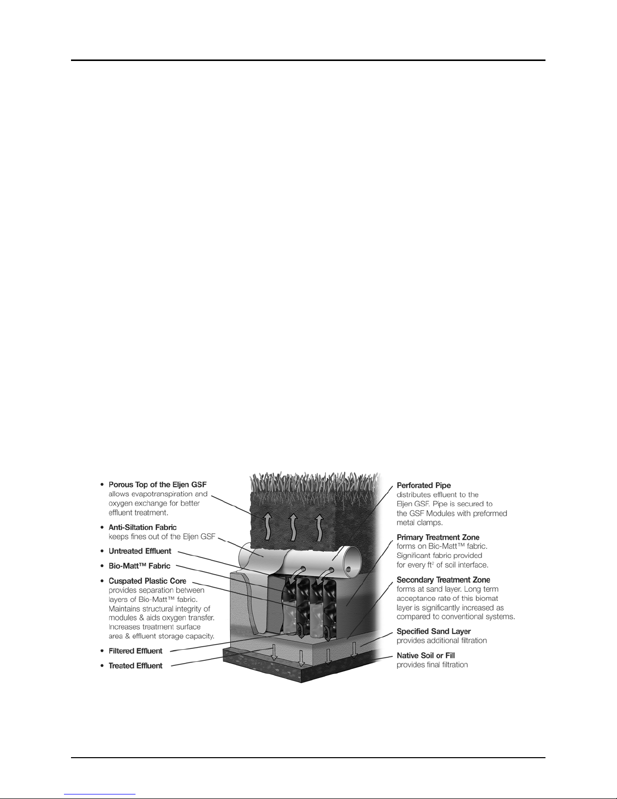
The Eljen GSF Geotextile Sand Filter
2014 New York GSF Design & Installation Manual 6 www.eljen.com
GSF System Description
The Eljen GSF Geotextile Sand Filter system is a cost-effective upgrade from other septic technologies.
Comprised of a proprietary two-stage Bio-Matt™ pre-treatment process, the geotextile modules apply a better-
than-secondary aerobic effluent to the soil, increasing the soil’s ability to accept the effluent. The result is
superior treatment in a smaller soil absorption area.
How the GSF System Works
Primary Treatment Zone
Perforated pipe is centered above the GSF module to distribute septic effluent over and into
corrugations created by the cuspated core of the geotextile module.
Septic effluent is filtered through the Bio-Matt fabric. The module’s unique design provides
increased surface area for biological treatment that greatly exceeds the module’s footprint.
Open air channels within the module support aerobic bacterial growth on the modules geotextile
fabric interface, surpassing the surface area required for traditional absorption systems.
An anti-siltation geotextile fabric covers the top and sides of the GSF module and protects the
Specified Sand and soil from clogging, while maintaining effluent storage within the module.
Secondary Treatment Zone
Effluent drips into the Specified Sand layer and supports unsaturated flow into the native soil. This
Specified Sand/soil interface maintains soil structure, thereby maximizing the available absorption
interface in the native soil. The Specified Sand supports nitrification of the effluent, which reduces
oxygen demand in the soil, thus minimizing soil clogging from anaerobic bacteria.
The Specified Sand layer also protects the soil from compaction and helps maintain cracks
and crevices in the soil. This preserves the soil’s natural infiltration capacity, which is
especially important in finer textured soils, where these large channels are critical for long-
term performance.
Native soil provides final filtration and allows for groundwater recharge.
FIGURE 1: GSF System Operation

2014 New York GSF Design & Installation Manual 7 www.eljen.com
1.0 Basic System Design
Jurisdiction: Please contact the local health department, watershed agencies, or Code Enforcement
Officer for site specific information to determine if there are any additional local design requirements beyond
the requirements of Appendix 75-A.
Absorption Field Size: Eljen requires residential systems use a recommended minimum of 5 B43 modules
per bedroom in either a trench or bed configuration. Tables 1 and 2 on Page 10 define the minimum trench
system length and estimated number of modules respectively. The system size is based on dividing the
design flow by the application rates given in Table 4B of Appendix 75-A and then applying Eljen’s 6 square
foot per linear foot (6 sf/ft) rating from Appendix 75-A.8 (c)(3)(iii) and minimums set in this manual. This will
determine the minimum trench length needed for each system. Trenches provide the most efficient design
and minimize quantities of Specified Sand required for installation. In trench designs, a minimum of 6 inches
of Specified Sand is required underneath and around the perimeter of the module row in the trench. Page
11 of this manual contains step-by-step sizing procedures for trench systems.
Tables 3 and 4 on Page 13 of this manual define the required absorption bed bottom area and the number
of modules in a bed configuration respectively. The same minimum number of modules is required by Eljen
in beds as specified in a trench for a given site. Depending on the number of rows, the length and total
number of modules will frequently increase in order to maintain an equal number of modules in each row.
The footprint is based on the infiltrative area calculated by dividing the design flow by the application rates
given in Table 5 of Appendix 75-A. In bed systems, the spacing between module rows will vary depending
on system geometry. A minimum of 12 inches of Specified Sand is required around the perimeter of the
module rows and a minimum of 12 inches of Specified Sand separating module rows. Equal numbers of
modules are required in each row for bed applications. Page 14 of this manual contains step-by-step sizing
procedures for bed systems.
Proposed Repair and Replacement system sizing shown in Tables 5 & 6 on Page 17 represent the
recommended minimum number of units and system area. Proposed sizing for Repair and Replacement
bed systems must be approved by the local health official if required. Eljen recommends that Repair and
Replacement bed systems are installed as “long and thin” as possible when site conditions allow.
Vertical Separation: As required by New York rules, in-ground designs require a minimum of 4 feet of
useable soil above bedrock, unsuitable soil, and seasonal high groundwater. The highest limiting condition
on the upslope side of the trench shall be at least 2-feet below the 6-inch Specified Sand layer as shown in
Figure 6.
Specified Sand for Trench and Bed Systems: The first 6 inches of Specified Sand immediately under,
between rows, and around the perimeter of the GSF system shall be an ASTM C33 Washed Concrete
Sand With Less Than 10% Passing a #100 Sieve And Less Than 5% Passing a #200 Sieve. Please
place a prominent note to this effect on each design drawing. See Page 4 of this manual for more
information on the ASTM C33 sand specification.
Fill for Shallow Trench Systems: As specified in 75-A.8.e, Eljen GSF systems may be installed on a
plowed ground surface with 2-feet of suitable soil between the bottom of the 6-inch Specified Sand layer
and the identified limiting conditions or restrictive soils. Specified Sand is place in the trenches in contact
with the native soils. The total depth of fill is determined by the elevation of the base of the GSF Specified
Sand layer and should not exceed 24 inches above the ground surface Additional fill is placed between
the trenches to an elevation of 12 inches above the module by using a light weight track machine. The
cover fill must demonstrate a percolation rate similar to the in situ while not exceeding the in situ soils
permeability. The cover fill normally includes a 4-inch to 6-inch layer of top soil that supports growth of a
robust vegetative cover capable of withstanding dry periods. System design and layout follow the
requirements for level or sloping site trenches with sizing based on the receiving soil percolation rate and
6 square feet per linear foot module rating in a Specified Sand lined trench. Minimum trench center
spacing is 8 feet on center based on trench separation of 4 feet of native soil. Designers are
recommended to specify greater trench spacing in slower soils where they seek to insure hydraulic
independence of each row of modules.
Placing GSF Modules: Each row of modules is laid level and end to end on top of a 6-inch minimum layer
of Specified Sand. No mechanical connection is required between the GSF modules.

2014 New York GSF Design & Installation Manual 8 www.eljen.com
1.0 Basic System Design
Distribution Pipe: SDR 35 or equivalent is required. Place perforated distribution pipe on top of GSF
modules with holes at the 5 and 7 o’clock positions. Complete system piping with non-perforated SDR 35
pipe and fittings. Refer to Sections 2.0 and 3.0 for level and serial piping details respectively. Secure pipe to
GSF modules with provided wire clamps, one clamp per Eljen module with both legs of the clamp against
the sides of the pipe.
Distribution Box or D-Box: Set gravity system d-box outlet inverts a minimum of 1/8-inch per foot distance
above invert of distribution pipe over the modules (2 inches minimum for pumped systems). The fill below
the distribution box and pipes connecting to it must be compacted to prevent settling. When pumped
systems are designed, specify oversized distribution boxes with baffles or velocity reduction piping.
Cover Fabric: Eljen provides an anti-siltation geotextile fabric with the system that is placed over the top
and sides of the module rows to prevent long-term siltation and failure. Cover fabric substitution is not
allowed. Fabric should drape vertically over the pipe and must neither block holes nor be stretched from
the top of the pipe to the outside edge of the modules. “Tenting” will cause undue stress on fabric and pipe.
Loose fabric could lead to blockage of pipe drain holes.
Backfill Grading and Storm water Management: Carefully place backfill over the modules, followed by
loam to complete a total minimum depth of 12 inches as measured from the top of the modules. Systems
with total cover that exceeds 18 inches as measured from the top of the module shall be vented at the distal
(far) end of the system. Backfill with suitable native soil that is clean and devoid of rocks larger than 2
inches. Finish grade to divert surface runoff from the absorption field area. Finish grade to prevent surface
ponding above and upslope of the absorption system. Seed loam to protect from erosion. Designers must
divert storm water from impervious surfaces around the absorption system. Where storm water infiltration
may create a seasonal perched water table, curtain drains may also be required upslope of the absorption
system.
Additional Factors Effecting Residential System Design: Homes with expected higher than normal
water due to luxury fixtures should have an increased septic tank capacity and/or multiple compartment
tanks and larger effluent absorption areas. Features that should be addressed by the designer include:
Homes with Jacuzzi style tubs and other high water use fixtures such as multiple shower heads,
etc.
Group home or day care facilities with expected higher than normal occupancy and water
consumption.
Homes with water conditioner backwash. Diversion from septic tank required, see Section 1.0.
Homes with in-sink garbage disposals or Jacuzzi style tubs must have an additional 250 gallon
sized tank based on Appendix 75-A requirements.
Designers should use discretion when there are multiple additional factors involved. Increase tank/system
size in proportion to excess flow. Multi-compartment and or Dual tanks in series provide the best
performance with better retention and separation of solids due to attenuation of flow.
System Geometry: Design systems as long and narrow as practical along site contours to minimize ground
water mounding especially in poorly drained, low permeability soils. Systems should be designed level with
equal length and number of modules per row.
Garbage Disposals: Design drawings shall include a note “Garbage Disposals Shall Not Be Used with
This System.” If owner insists on using a garbage disposal, use a 2 compartments septic tank and increase
tank size by 250 gallons. An appropriate sized septic tank effluent filter must also be used. Failure to adhere
to these recommendations could void product warranty.
2014 New York GSF Design & Installation Manual 9 www.eljen.com
1.0 Basic System Design
Water Conditioners: Water conditioners can adversely affect septic tank treatment and add to the
hydraulic load of the absorption field area. See 75-A.3 for DOH recommendations. Discharge from
residential water conditioners shall be into a separate alternative disposal system integrated with a
storm water groundwater recharge system. The location shall be as far as possible from surface
aquifer wells and the GSF system. Failure to adhere to these recommendations could void product
warranty.
System Venting: All systems require sufficient oxygen supply to the GSF system to maintain proper long
term effluent treatment. If a p-trap is installed between the septic tank and the home it should be removed to
allow air to flow from the GSF up through the home vent.
The following situations require venting at the distal (far) end of the GSF system:
Any system approved with more than 18 inches of total cover as measured from the top of the
modules to finished grade.
Any pump systems approved with a depth greater than 18 inches require by-pass lines from the
distribution box back to the pump station riser or septic tank riser as shown in Figures 17 and 18 on
Page 42. This will ensure continuity of air flow around the pump station or septic tank and back up
the home vent stack.
Vehicular Traffic: All vehicular traffic is prohibited over the GSF system. Appropriate markers and barriers
such as fencing, bollard or landscape timber should be used to prevent vehicular traffic from driving over
the GSF System. Wheel traffic can crush distribution pipes above the modules and result in blockage and
loss of effluent delivery to parts of the system.
Septic Tanks: Many designers are now specifying dual compartment septic tanks or dual tanks installed in
series for all their systems. Eljen supports this practice as it helps to assure long system life by reducing
suspended solids and BOD to the absorption field area. Gas baffles or effluent filters are also
recommended. Listed in the chart below are the septic tank capacity guidelines from Appendix 75-A.6,
Table 3.
MinimumSepticTankCapacities
NumberofBedrooms MinimumTankCapacity
(Gallons)
MinimumLiquidSurface
Area
(SquareFeet)
1‐3 1,000 27
4 1,250 34
5 1,500 40
6 1,750 47
NOTE:Tanksizerequirementsformorethansixbedroomsshallbecalculatedby
adding250gallonsandseven(7)squarefeetofsurfaceareaforeachadditional
bedroom.Agarbagegrinderorspatubshallbeconsideredequivalenttoan
additionalbedroomfordeterminingtanksize.
Septic Tank Filters and Risers: Wastewater effluent filters are required as a means of preventing solids
from leaving the septic tank and encouraging management of the tank solids. Eljen recommends that
access risers to grade be used on any septic tank with a filter to provide easy access for inspection and
maintenance.
2014 New York GSF Design & Installation Manual 10 www.eljen.com
2.0 Trench Configuration Sizing
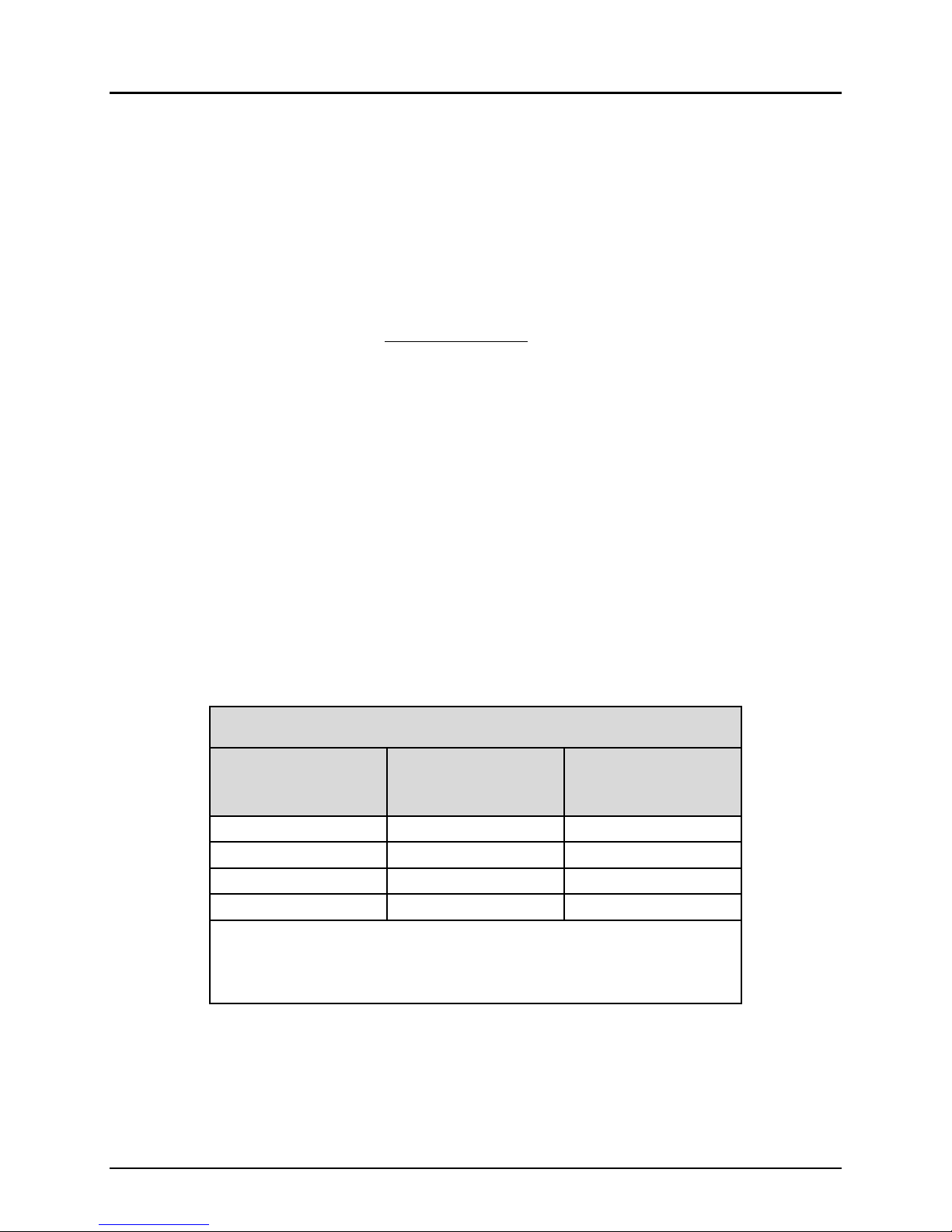
To determine the minimum linear feet of trench required per Appendix 75-A, use Table 1 and identify the
soil classification rating and then the number of bedrooms and the associated design flow of the dwelling.
The intersection of these rows and columns will define the minimum linear feet of trench required for the
system.
Table1:B43GSFTrenchSizingTable‐MinimumLinearFeetperSystem*
Basedon6sf/lfSizingCredit
Percolation
Rate
(Min/In)
Application
Rate
(GPD/SF)
2Bedroom 3Bedroom 4Bedroom EachAdditional
Bedroom
FlowRate
(Gal/Day)
FlowRate
(Gal/Day)
FlowRate
(Gal/Day)
FlowRate
(Gal/Day)
220 260 300 330 390 450 440 520 600 110 130 150
1‐5 1.2 40 40 44 48 56 64 64 76 84 20 20 24
6‐7 1.0 40 44 52 56 68 76 76 88 100 20 24 28
8‐10 0.9 44 52 56 64 76 84 84 100 112 24 28 28
11‐15 0.8 48 56 64 72 84 96 92 112 128 24 28 32
16‐20 0.7 56 64 72 80 96 108 108 124 144 28 32 36
21‐30 0.6 64 76 84 92 112 128 124 148 168 32 40 44
31‐45 0.5 76 88 100 112 132 152 148 176 200 40 44 52
46‐60 0.45 84 100 112 124 148 168 164 196 224 44 52 56
* The table above represents the minimum length of a trench based on Gallons/Day, respective application rates, and minimum
modules required per bedroom. It does not take into account module length and required Specified Sand at the end of the
trench row. All final system lengths must add 1-foot of length to compensate for the 6-inches of Specified Sand required at the
end of each system row.
To determine the number of modules required for the system, use Table 2 and identify the soil
classification rating and then the number of bedrooms and the associated design flow of the dwelling. The
intersection of these rows and columns will define the number of modules required for the system.
Table 2 has been adjusted to provide an Eljen required minimum of 5 modules per bedroom and has
been rounded up to the next full module in systems that had partial modules as calculated to meet
NYDOH sizing requirements. A step by step sizing procedure for the sizing of trench systems is on Page
11 of this manual.
Table2:B43GSFTrenchSizingTable‐ModulesperSystem
Basedon6sf/lfSizingCredit
Percolation
Rate
(Min/In)
Application
Rate
(GPD/SF)
2Bedroom 3Bedroom 4Bedroom EachAdditional
Bedroom
FlowRate
(Gal/Day)
FlowRate
(Gal/Day)
FlowRate
(Gal/Day)
FlowRate
(Gal/Day)
220 260 300 330 390 450 440 520 600 110 130 150
1‐5 1.2 10 10 11 12 14 16 16 19 21 5 5 6
6‐7 1.0 10 11 13 14 17 19 19 22 25 5 6 7
8‐10 0.9 11 13 14 16 19 21 21 25 28 6 7 7
11‐15 0.8 12 14 16 18 21 24 23 28 32 6 7 8
16‐20 0.7 14 16 18 20 24 27 27 31 36 7 8 9
21‐30 0.6 16 19 21 23 28 32 31 37 42 8 10 11
31‐45 0.5 19 22 25 28 33 38 37 44 50 10 11 13
46‐60 0.45 21 25 28 31 37 42 41 49 56 11 13 14

2014 New York GSF Design & Installation Manual 11 www.eljen.com
Residential Sizing Procedure for Trench Systems
Note: Refer to Sizing Tables 1 and 2 on Page 10 for residential trench systems or Reference Appendix
75-A.8 and Table 4B from Appendix 75-A for absorption trench design and installation requirements. This
design example is for illustration purposes only. All numbers can be rounded up to make designing and
installing easier. Please contact Eljen Corporation with any questions.
Procedure
1. Define the flow and absorption trench bottom area requirements:
Use Table 1, on Page 10, of this manual to identify the flow and minimum linear feet of GSF
trench required. Use the linear footage value where the percolation rate of the site intersects the
number of bedrooms for the associated design flow of the dwelling.
Or use Appendix 75-A, Table 4B, to determine the appropriate application rate and complete the
following calculations:
o Design Flow per Bedroom x Number of Bedrooms = Daily Flow Rate (gpd).
o Daily Flow Rate (gpd) ÷ Application Rate (gpd/ft2) = Required Trench Bottom Area (ft2).
o Required Trench Bottom Area (ft2) ÷ 6 ft2/lf (GSF Module Rating) + 1’ for the sand
envelope at the beginning and end of the trench = Minimum linear feet of trench required
for the system.
Example Calculation:
3 bedrooms, 110 gpd/br with a percolation rate of 13 mpi:
110 gpd/br x 3 br = 330 gpd daily flow rate.
330 gpd daily flow rate ÷ 0.80 gpd/ft2 application rate = 412.5 ft2 trench bottom area
required.
412.5 ft2 required trench bottom area ÷ 6 ft2/lf (GSF module rating) = 68.75 linear feet of
trench required rounded up to 69’.
2. Estimate the number of GSF modules and define the row and trench length:
Use Table 2, on Page 10, of this manual and identify the number of GSF modules required for the
system. Find the value where the percolation rate of the site intersects the number of bedrooms
and the associated design flow of the dwelling. Choose the number of trenches desired and round
up to the same number of modules per trench if required.
Or take the linear feet required for the system from Step 1 ÷ 4 ft length per module = number of
GSF modules for the system. Choose the longest possible trench design keeping the same
number of modules per trench.
Example Calculation:
69 linear feet of trench required ÷ 4 ft length per module = 17.25 GSF modules.
Using 3 module rows for the system, round up to 6 modules per row if there is room for a total
of 18 modules for the system.
Note: Continued on next page.

2014 New York GSF Design & Installation Manual 12 www.eljen.com
Residential Sizing Procedure for Trench Systems
3. Define the trench length:
Define the trench length based on the number of modules plus 1’ for the sand at each end of the
trench (6” at each end):
Example Calculation:
6 modules x 4’ module length + 1’ = 25’ per trench.
Or for minimum size trench length based on total trench length required by Appendix 75-A
complete the following calculations:
o Divide total trench length by the number of trenches and maximize the number of
modules that will fit in each trench.
Example Calculation:
69’ ÷ 3 trenches = 23’ per trench.
Number of Modules = 23’ trench length ÷ 4’ per module = 5.75 per trench, rounded down to 5
modules per trench.
The module length = 5 modules x 4’ length per module = 20’.
Specified Sand at each end of the trench = (23’ trench length – 20’ module row length) ÷ 2 =
18” of Specified Sand at each end of the trench.
The system designer can decide how to configure the system based on site characteristics. In the
example listed above, possible designs could include:
A single row of modules with optional distribution box at the beginning of the trench used for
inspection.
A “butterfly” configuration, one row of modules in a single trench line with a distribution box
located at the center of the system.
Multiple trench configurations with equal number of modules in each trench following a
distribution box.
Multiple trenches on a hillside using drop boxes ahead of unequal length trenches.
Add up to 18 inches of Specified Sand at the end of rows, instead of modules, in systems that
“come close” to meeting trench length minimums.
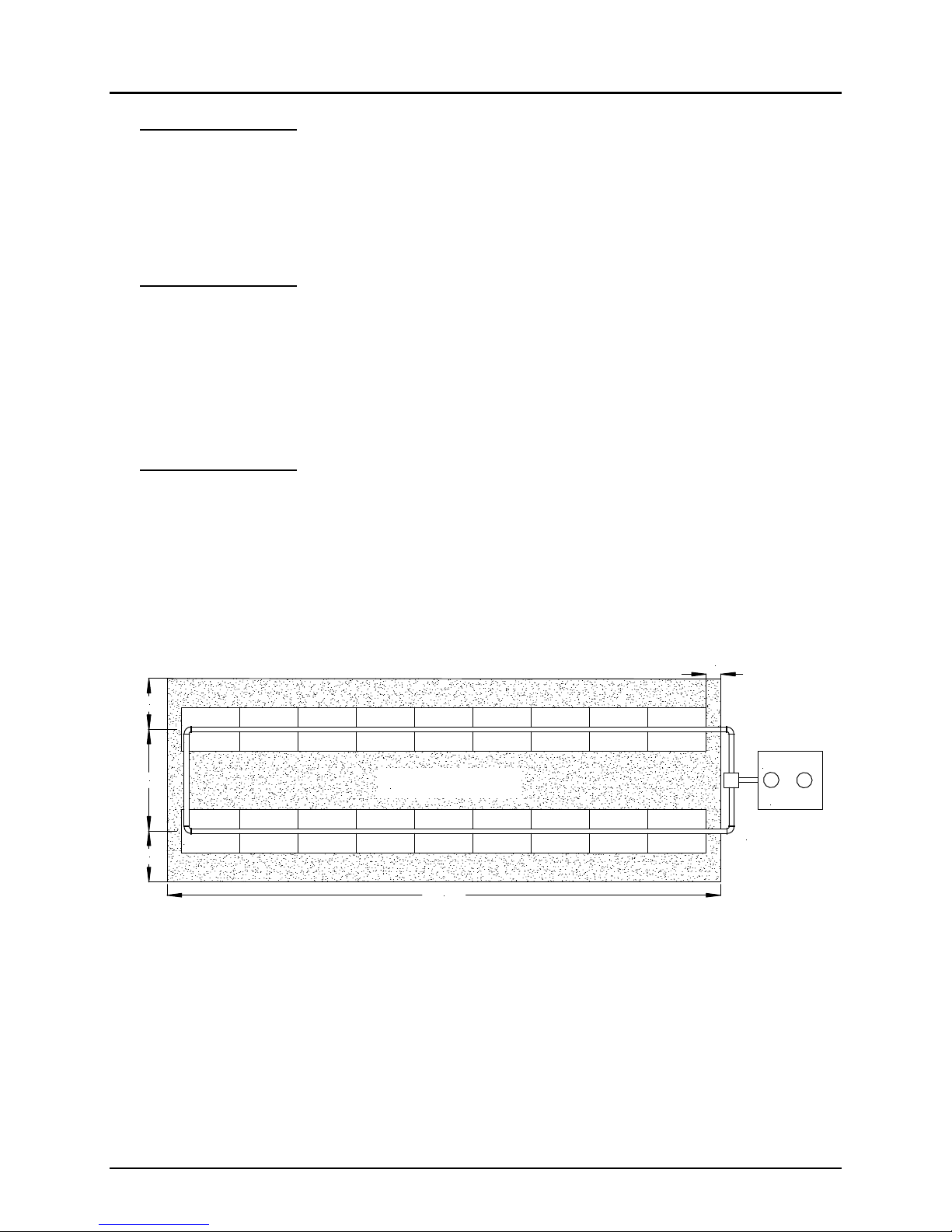
Figure 2: Example Sizing of a Trench System
3 bedrooms – 110 gpd/br – Percolation rate of 13 mpi
6"
6"
36"
48"
SEPTIC
TANK
ASTM C33
SAND
NATIVE SOIL
ASTM C33
SAND
48"
4' MINIMUM
37'

2014 New York GSF Design & Installation Manual 13 www.eljen.com
3.0 Bed Configuration Sizing
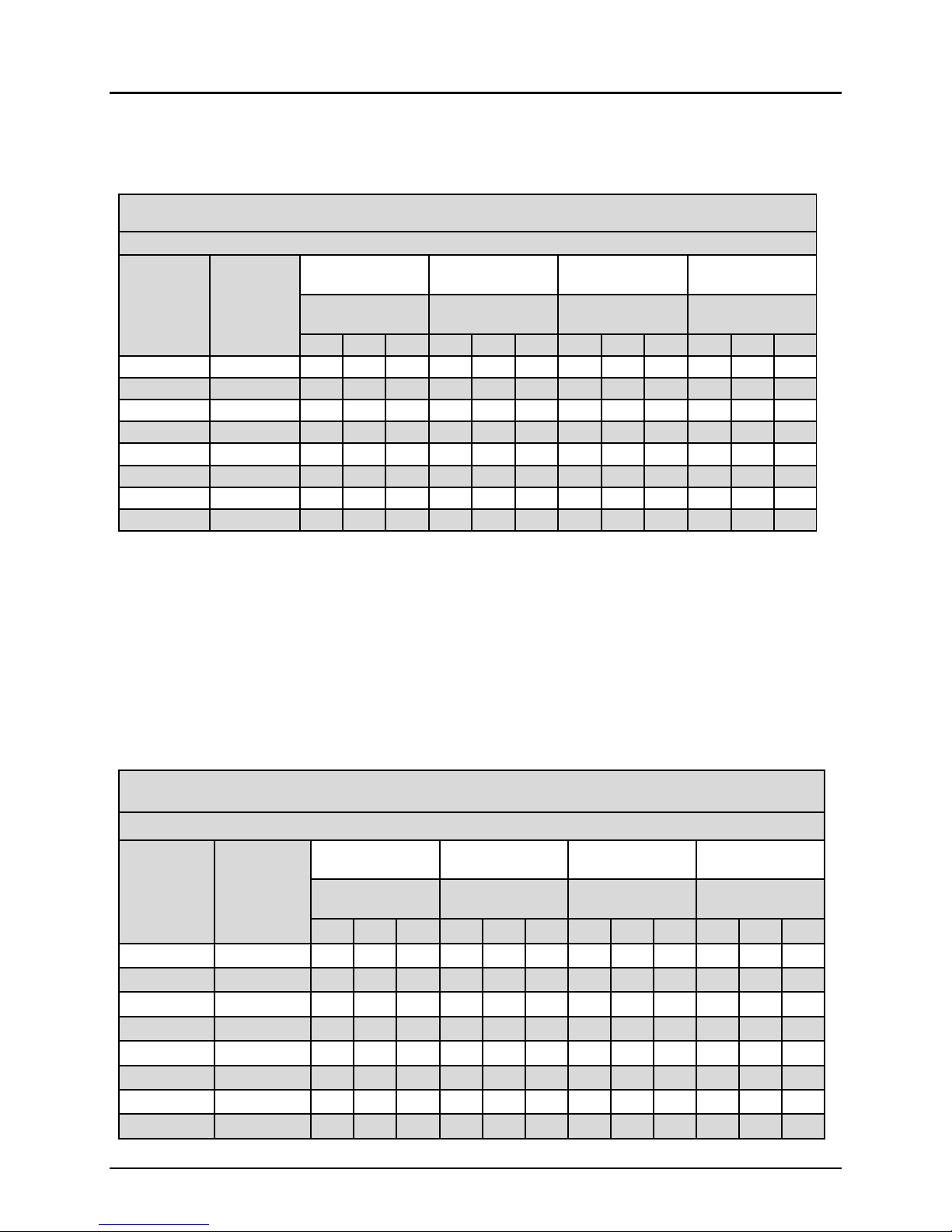
To determine the square feet of absorption bottom area required for the bed system, use Table 3 and
identify the soil classification rating and then the number of bedrooms and associated design flow of the
dwelling. The intersection of these rows and columns will define the square feet of absorption area
required for the bed system.
Table3:B43GSFBedSizingTable‐SquareFeetofAbsorptionAreaperSystem
Percolation
Rate
(Min/In)
Application
Rate
(GPD/SF)
2Bedroom 3Bedroom 4Bedroom EachAdditional
Bedroom
FlowRate
(Gal/Day)
FlowRate
(Gal/Day)
FlowRate
(Gal/Day)
FlowRate
(Gal/Day)
220 260 300 330 390 450 440 520 600 110 130 150
1‐5 0.95 232 274 316 347 411 474 463 547 632 116 137 158
6‐7 0.80 275 325 375 413 488 563 550 650 750 138 163 188
8‐10 0.70 314 371 429 471 557 643 629 743 857 157 186 214
11‐15 0.60 367 433 500 550 650 750 733 867 1000 183 217 250
16‐20 0.55 400 473 545 600 709 818 800 945 1091 200 236 273
21‐30 0.45 489 578 667 733 867 1000 978 1156 1333 244 289 333
>30 Note:DesignwithTrenchConfigurations‐NotAcceptableforBedConfigurationsUnderAppendix75‐A
To determine the number of modules required for the bed system, use Table 4 and identify the soil
classification rating and then the number of bedrooms and associated design flow of the dwelling. The
intersection of these rows and columns will define the number of modules required for the bed system.
These sizing tables have been adjusted to provide an Eljen required minimum of 5 modules per bedroom,
and have been rounded up to the next full module in systems that had partial modules as calculated to
meet DOH sizing requirements. A step by step sizing procedure for the sizing of bed systems is on Page
14 of this manual.
Lower absorption rates assigned by DOH for beds in heavier clay loam soils allow greater spacing of
module rows. This lower density of modules disperses the effluent from each row over a larger area and
thereby reduces the application of effluent onto the soil. For very large beds call Eljen for more information
on how the effluent can be managed to improve dispersion using gravity or dosed d-box designs.
Table4:B43GSFBedSizingTable‐ModulesperSystem
Percolation
Rate
(Min/In)
Application
Rate
(GPD/SF)
2Bedroom 3Bedroom 4Bedroom EachAdditional
Bedroom
FlowRate
(Gal/Day)
FlowRate
(Gal/Day)
FlowRate
(Gal/Day)
FlowRate
(Gal/Day)
220 260 300 330 390 450 440 520 600 110 130 150
1‐5 0.95 10 10 11 15 15 16 20 20 21 5 5 6
6‐7 0.80 10 11 13 15 17 19 20 22 25 5 6 7
8‐10 0.70 10 13 14 16 19 21 21 25 28 6 7 7
11‐15 0.60 12 14 16 18 21 24 23 28 32 6 7 8
16‐20 0.55 14 16 18 20 24 27 27 31 36 7 8 9
21‐30 0.45 16 19 21 23 28 32 31 37 42 8 10 11
>30 Note:DesignwithTrenchConfigurations‐NotAcceptableforBedConfigurationsUnderAppendix75‐A

2014 New York GSF Design & Installation Manual 14 www.eljen.com
Residential Sizing Procedure for Bed Systems
Note: Refer to Sizing Tables 3 and 4 on Page 13 for residential bed systems or reference Appendix
75-A.8(g) and Table 5 from Appendix 75-A for absorption bed design and installation requirements.
This design example is for illustration purposes only. All numbers can be rounded up to make
designing and installing easier. Please contact Eljen Corporation with any questions.
Procedure
1. Define the flow and absorption bed basal area requirements:
Define the design flow based on the flow per bedroom and home size.
Use Table 3, on Page 13, of this manual and identify the basal bed area requirement by finding
the square footage value where the percolation rate of the site intersects the number of bedrooms
and the associated design flow of the dwelling.
Or use Appendix 75-A, Table 5, to determine the appropriate application rate and the following
calculation: Daily Flow Rate (gpd) ÷ Application Rate (gpd/ft2) = Required Bed Bottom Area (ft2).
Example Calculation: 4 bedrooms – 110 gpd/br – Percolation rate of 15 mpi.
110 gallons per bedroom x 4 BR = 440 gpd.
440 gpd ÷ 0.60 gpd/ft2 = 733 ft2 Absorption Bed Basal Area Required.
2. Use Table 4, on Page 13, of this manual and identify the total number of GSF modules for the system
by finding the value where the percolation rate of the site intersects the number of bedrooms for the
specified design flow of the dwelling.
Example Calculation: Using Table 4, with a 4-bedroom home, in 20 minutes per inch
percolation rate soil, with a design flow of 440 gpd. The application rate equals 0.60 gpd/sf and
number of modules required equals 23 modules.
3. Estimate the number of modules and system length based on equal number of modules per
row. For example; if 23 modules are required use 2 rows of 12 B43 modules.
4. Define the bed length:
Based on site conditions and the number of modules needed for the system, choose the number
of module rows for the system.
Define the bed length by dividing the total number of modules by the number of rows chosen,
round up the number of modules to make all rows equal. Ensure that bed system geometry is
narrow with no more than three rows of modules in finer textured soils.
Multiply the number of modules per row by 4 feet (the length of a GSF module) and add 2 feet
(for the specified sand on both ends).
Number of modules (Table 4) ÷ number of rows = Modules per Row.
Number of modules per row x 4 feet plus 2 feet = Bed Length.
Note: Continued on next page.
2014 New York GSF Design & Installation Manual 15 www.eljen.com
Residential Sizing Procedure for Bed Systems
Example Calculation:
For the above example, choose 2 rows with 12 B43 modules per row = 24 modules.
(12 modules x 4’ module length) + (1’ sand perimeter) = 50 feet for the bed length.
5. Define the bed width:
Take the Absorption Bed Basal Area (Footprint) ÷ Bed Length (Step 4) = Bed Width.
Example Calculation:
Using 2 rows, the preferred narrow design = 733 ft2 ÷ 50 ft = 14.66 feet or round up to 15’
for ease of layout. Note: Exact measurements can always be used.
6. Determine the module row spacing in the bed:
Spacing between rows = bed width ÷ number of rows = Center Spacing for level systems.
Use 1/2 center spacing between the outside module rows and the side of the bed (or a minimum
of 1 foot).
Example Calculation:
15 feet ÷ 2 = 7.5’ Center-To-Center Module Row Spacing
7.5 ÷ 2 = 3.75’ spacing between the center of the outside module rows and the side of the bed.
Figure 3: Example Sizing of a Bed System
4 bedrooms – 110 gpd/br – Percolation rate of 15 mpi
SEPTIC
TANK
ASTM C33 SAND
12"
3.75'
7.5'
3.75'
50.0'

2014 New York GSF Design & Installation Manual 16 www.eljen.com
4.0 Repair and Replacement Bed System Sizing
To determine the square feet of absorption bottom area required for the bed system, use Table 5 and
identify the soil classification rating and then the number of bedrooms and associated design flow of the
dwelling. The intersection of these rows and columns will define the square feet of absorption area
required for the repair or replacement bed system.
To determine the number of modules required for the bed system, use Table 6 and identify the soil
classification rating and then the number of bedrooms and associated design flow of the dwelling. The
intersection of these rows and columns will define the number of modules required for the bed system.
General Guidelines for Repair and Replacement System Sizing
Proposed Repair and Replacement system sizing shown in Tables 5 & 6 represent the minimum
number of units and system area. Number of modules and system area can always be increased
to meet local requirements and the needs of the design and site.
Proposed sizing for Repair and Replacement bed systems must be approved by the local health
official if required.
Minimum number of Eljen B43 modules per bedroom is 5 B43 modules.
Minimum edge to edge module spacing for Repair and Replacement bed systems is 12 inches.
Maximum length per system row is 60 feet for gravity, 75 feet for pump dosing, and 100 for
pressure distribution.
Tables 5 & 6 are based on a minimum design flow of 150 gpd/bedroom. For lower flows, please
contact Eljen Corporation for technical support.
Eljen recommends that Repair and Replacement bed systems are installed as “long and thin” as
possible when site conditions allow.
System rows must use an equal number of modules per row. System area may need to be
increased to accommodate additional units.
2014 New York GSF Design & Installation Manual 17 www.eljen.com
4.0 Repair and Replacement Bed System Sizing
Table5:B43GSFBedSizingChartforRemediation&ReplacementSystems
MinimumSquareFeetofAbsorptionAreaperSystem
Percolation
Rate
(Min/In)
Application
Rate
(Adjusted)
(GPD/SF)
2Bedroom 3Bedroom 4Bedroom EachAdditional
Bedroom
FlowRate
(Gal/Day)
FlowRate
(Gal/Day)
FlowRate
(Gal/Day)
FlowRate
(Gal/Day)
300 450 600 150
1‐5 1.57 192 287 383 96
6‐7 1.33 226 339 452 113
8‐10 1.17 257 385 513 129
11‐15 1.00 300 450 600 150
16‐20 0.92 327 490 653 164
21‐30 0.75 400 600 800 200
31‐45 0.67 448 672 896 224
46‐60 0.58 518 776 1035 259
61‐80 0.50 600 900 1200 300
81‐100 0.42 715 1072 1429 358
101‐120 0.33 910 1364 1819 455
Table6:B43GSFBedSizingChartforRemediation&ReplacementSystems
MinimumNumberofB43Modules&LinearFeetperSystem
Percolation
Rate
(Min/In)
Application
Rate
(Adjusted)
(GPD/SF)
2Bedroom 3Bedroom 4Bedroom EachAdditional
Bedroom
FlowRate
(Gal/Day)
FlowRate
(Gal/Day)
FlowRate
(Gal/Day)
FlowRate
(Gal/Day)
300 450 600 150
Min
Number
of
Modules
Linear
Feet
Min
Number
of
Modules
Linear
Feet
Min
Number
of
Modules
Linear
Feet
Min
Number
of
Modules
Linear
Feet
1‐5 1.57 10 40 12 48 16 64 4 16
6‐7 1.33 10 40 15 60 19 76 5 20
8‐10 1.17 11 44 17 68 22 88 6 24
11‐15 1.00 13 52 19 76 25 100 7 28
16‐20 0.92 14 56 21 84 28 112 7 28
21‐30 0.75 17 68 25 100 34 136 9 36
31‐45 0.67 19 76 28 112 38 152 10 40
46‐60 0.58 22 88 33 132 44 176 11 44
61‐80 0.50 25 100 38 152 50 200 13 52
81‐100 0.42 30 120 45 180 60 240 15 60
101‐120 0.33 38 152 57 228 76 304 19 76

2014 New York GSF Design & Installation Manual 18 www.eljen.com
4.0 Repair and Replacement Bed System Sizing
Note: Refer to Sizing Tables 5 and 6 on Page 17 for Repair and Replacement bed systems. Repair
and Replacement bed systems must be approved by the local health official if required. This design
example is for illustration purposes only. All numbers can be rounded up to make designing and
installing easier. Please contact Eljen Corporation with any questions.
Procedure
1. Define the flow and absorption bed basal area requirements:
Define the design flow based on 150 gpd/bedroom. For lower flows, please contact Eljen
Corporation for technical support.
Use Table 5, on Page 17, of this manual and identify the basal bed area requirement by finding
the square footage value where the percolation rate of the site intersects the number of
bedrooms.
Example Calculation: 4 bedrooms – 150 gpd/br – Percolation rate of 20 mpi.
150 gallons per bedroom x 4 BR = 600 gpd.
600 gpd ÷ 0.92 gpd/ft2 = 653 ft2 Absorption Bed Basal Area Required.
2. Use Table 6, on Page 17 of this manual and identify the total number of GSF modules for the system
by finding the value where the percolation rate of the site intersects the number of bedrooms for the
specified design flow of the dwelling
Example Calculation: Using Table 6, with a 4-bedroom home, in 20 minutes per inch
percolation rate soil, with a design flow of 600 gpd. The application rate equals 0.92 gpd/sf and
number of modules required equals 28 modules.
3. Estimate the number of modules and system length based on equal number of modules per
row. For example; if 28 modules are required use 2 rows of 14 modules.
4. Define the bed length:
Based on site conditions and the number of modules needed for the system, choose the number
of module rows for the system.
Define the bed length by dividing the total number of modules by the number of rows chosen,
round up the number of modules to make all rows equal. Ensure that bed system geometry is
narrow with no more than three rows of modules in finer textured soils.
Multiply the number of modules per row by 4 feet (the length of a GSF module) and add 2 feet
(for the specified sand on both ends).
Number of modules (Table 6) ÷ number of rows = Modules per Row.
Number of modules per row x 4 feet plus 2 feet = Bed Length.
Note: Continued on next page.

2014 New York GSF Design & Installation Manual 19 www.eljen.com
4.0 Repair and Replacement Bed System Sizing
Example Calculation:
For the above example, choose 2 rows with 14 B43 modules per row = 28 modules.
(14 modules x 4’ module length) + (1’ sand perimeter) = 58 feet for the bed length.
5. Define the bed width:
Take the Absorption Bed Basal Area (Footprint) ÷ Bed Length (Step 4) = Bed Width.
Example Calculation:
653 ft2 ÷ 58’ = 11.25’ for a 2 row bed width. Note: All numbers can be rounded up to make
designing and installing easier.
6. Determine the module row spacing in the bed:
Spacing between rows = bed width ÷ number of rows = Center Spacing for level systems.
Use 1/2 center spacing between the outside module rows and the side of the bed (or a minimum
of 1 foot).
Example Calculation:
11.25 feet ÷ 2 rows = 5.625’ Center-To-Center Module Row Spacing
5.625’ ÷ 2 rows = 2.8’ spacing between the center of the outside module rows and the side
of the bed
Note: Elevated or Mound systems can use minimum edge to edge spacing of 1 foot with a 1 foot sand
perimeter to minimize module sand application area. Basal area must be sized according to Table 5.
Figure 4: Example Sizing of a Repair and Replacement Bed System
4 bedrooms – 150 gpd/br – Percolation rate of 20 mpi
SEPTIC
TANK
ASTM C33 SAND
12"
58.0'
56'
5.625'
2.8'
11.25'

2014 New York GSF Design & Installation Manual 20 www.eljen.com
5.0 GSF Sand Filter Design
Appendix 75-A provides minimum specifications for sand filter design. The GSF modules replace
aggregate and provide additional pretreatment capacity so only 12 inches of specified sand is required
below the modules. This allows remediation of an existing sand filters with minimal, if any, sand
replacement. The modules can be installed on the exposed clean sand with specified sand placed around
the modules as required in any bed design. Minimum spacing of 12 inches between modules and 6
inches along the sides applies to all installations. Greater spacing is allowed for filters that exceed state
minimum requirements shown in Table 5 of this manual.
The following sizing of sand filters is based on the 2010 Appendix 75-A loading rate of 1.15 gallons per
day per square foot. Sizing will vary based on required design flows. Minimum sizing required by Eljen is
15 B43 modules or 252 square feet. Figures 5 and 6 show the cross section and plan view for the filters.
A minimum of 6 inches of specified sand filter sand is required on both sides and the end of each row of
modules. Design guidance uses 24 square feet per module with the total number modules rounded up for
an equal number of modules per row.
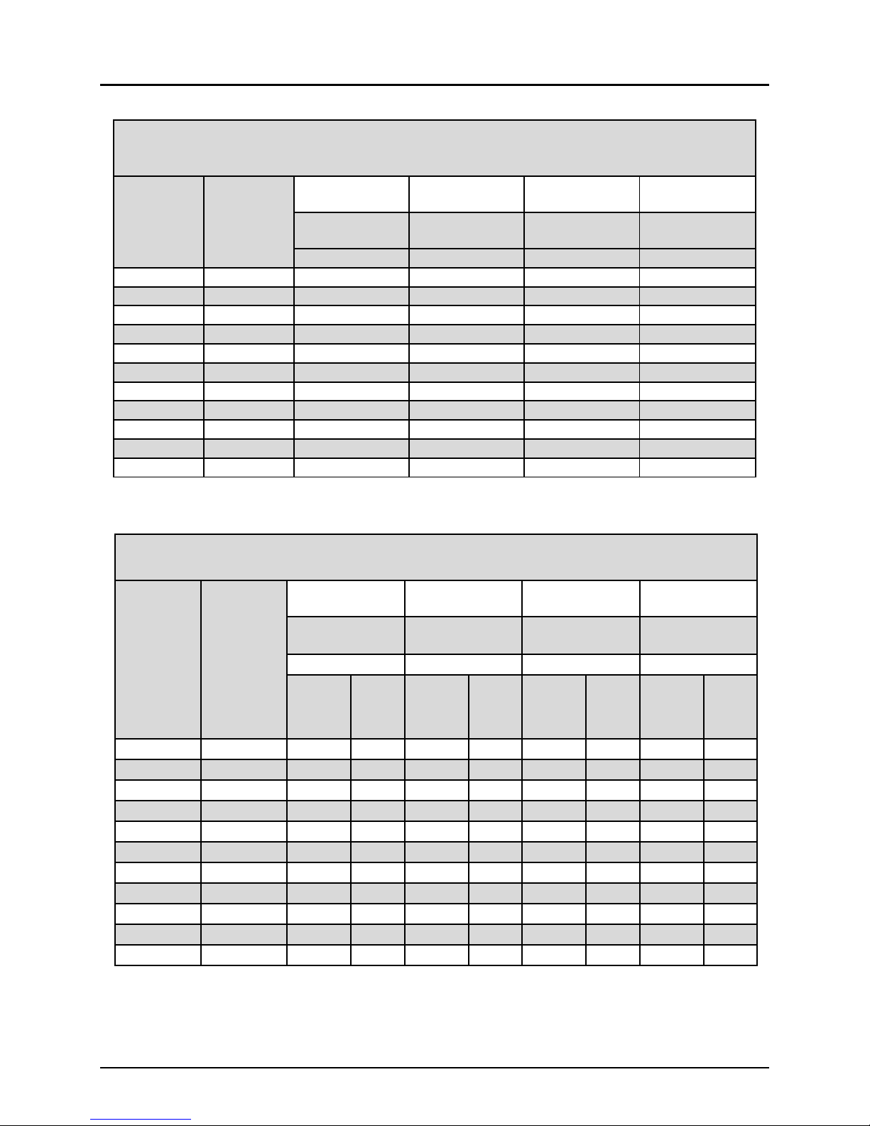
Table 7: B43 GSF Sand Filter Sizing Using Gravel Based Design
Number
of
Bedrooms
Design
Flow
Gal/Day
Square
Feetof
System
Area
(1.15)
(gpd/sf)
Required
Sand
Module
Length
(6sf/lf)
Numberof
Rows
Numberof
Rows
BedWidth
(ft)
BedWidth
(ft)
8 12 16 8 12 16
Numberof
Rows
Numberof
Rows
2 3 4 2 3 4 2 3 4 2 3 4
Modules
perRow
Total
Number
ofModules
BedLength
(ft)
TotalSystem
Area(sf)
3 330 287 47.8 8 5 5 16 15 20 33 21 21 264 252 336
3 390 339 56.5 8 5 516 15 20 33 21 21 264 252 336
3 450 391 65.2 9 6 5 18 18 20 37 25 21 296 300 336
4 440 383 63.8 8 6 416 18 16 33 25 17 264 300 272
4 520 452 75.4 10 7 5 20 21 20 41 29 21 328 348 336
4 600 522 87.0 11 8 622 24 24 45 33 25 360 396 400
5 550 478 79.7 10 7 5 20 21 20 41 29 21 328 348 336
5 650 565 94.2 12 8 624 24 24 49 33 25 392 396 400
5 750 652 108.7 14 10 7 28 30 28 57 41 29 456 492 464
6 660 574 95.7 12 8 624 24 24 49 33 25 392 396 400
6 780 678 113.0 15 10 8 30 30 32 61 41 33 488 492 528
6 900 783 130.4 17 11 934 33 36 69 45 37 552 540 592
*Note: Minimum of 15 modules and 252 square feet required.
Gravity application of the septic effluent is possible if the receiving sump uses a pump to apply the
effluent to the receiving trenches. This setup allows recycling a fraction of the treated effluent back to the
d-box that precedes the GSF filter. Use of an orifice splitting manifold allows adjustment of the recycle
ratio. Contact Eljen if you have any questions on the design hydraulic splitting device.
For dosed filter designs use 1 gallon per foot of media per dose. Contact Eljen if you have any questions
on the source and design for these tanks.
Other manuals for GSF
3
Table of contents
Other Eljen Water Filtration System manuals


Popular Water Filtration System manuals by other brands


BWT
BWT bestcamp Mini Installation and service manual

LifeSource
LifeSource ScaleSolver SSC-4025 Installation, operation and maintenance manual

Filters itm
Filters itm FL Series user manual

EcoWater
EcoWater EWS-EU500/230 owner's manual

Intec
Intec FDC/aerofilter STC SR00180SE instructions

JRC
JRC NSVS1176 manual


