Elk M1XSP Instruction Manual

Table of Contents
M1XSP Installation and Setup.....................................................................................................................................2
ELK-M1 Data Bus E.O.L. Termination..........................................................................................................................3
INSTEON ** Lighting Control ONLY **.......................................................................................................................4
Updating/Replacing Firmware in the ELK-M1XSP.....................................................................................................8
Firmware Release Notes..............................................................................................................................................8
Version 50.1.4 released Jan 20, 2009 ....................................................................................................................8
Version 50.1.2 released Jan 5, 2008......................................................................................................................8
Version 50.0.28 released June 2, 2008..................................................................................................................8
Version 50.0.26 released Mar 9, 2007....................................................................................................................9
Version 50.0.22 released June 23, 2006 ................................................................................................................9
PO Box 100 • Hwy. 70W • Hildebran, NC 28637 • USA • 828-397-4200 • http://www.elkproducts.com
Firmware and/or bootware releases contain enhancements and/or resolutions for issues found in previous releases.
For the latest Updates refer to the Elk Website. http://www.elkproducts.com
Copyright 2012, Elk Products, Inc. No portion of this document shall be copied or distributed without the express written permission of Elk.
8/11/2014
ELK-M1XSP Serial Port Expander
Supplementary Instructions & Release Notes
for
Firmware Version 50.X.X
This version provides M1 Integration to:
INSTEON ** Lighting Control ONLY **
Page2 M1XSP Supplementary Instructions and Release Notes
M1XSP Diagnostic LED indicator
Slow blink (1/2 sec.) = Normal communication with M1.
Fast flicker = Communicating with other equipment (Thermostat, Lighting Controller, PC, etc.)
No blink = No communication with M1. Unit might be unplugged or powered off.
M1XSP Installation and Setup
1. The M1XSP operates on the M1 Keypad data bus and may therefore be remoted near the equipment being interfaced.
2. Before making any wiring connections, turn Off the M1 Master Power Switch.
3. Connect terminals +12V, A, B, and Neg from the M1XSP to the M1's Keypad Data Bus (terminals +VKP, Data A, Data B, &
Neg). NOTE: Refer to the M1 Installation Manual and the M1DBH information in this manual about proper
connections of data bus devices with multiple homerun cables.
4. There are 4 address switches, each with a position of OFF or ON (binary value 0 or 1) and a decimal equivalent value of
(1, 2, 4, or 8). The total decimal value of the "ON" switches equates to the data bus address. As a rule, the first M1XSP
should be set to address 1. If more than 1 M1XSP is installed, set each one to a unique (sequential) address (2, 3, etc).
5. Set the "Mode", "Baud", and other necessary jumpers according to the Installation diagrams on previous pages.
6. After all connections are complete, turn On the M1 Master Power Switch.
7. Enroll the M1XSP into the M1 Control. From the Keypad access the Installer level programming and select Menu 01-Bus
Module Enrollment. Press the right arrow key to start the enrollment. Onceenrollment has completed, press the right
arrow key to view results. Enrolled M1XSPs will show up as type 5 (T5) followed by the specific address number.
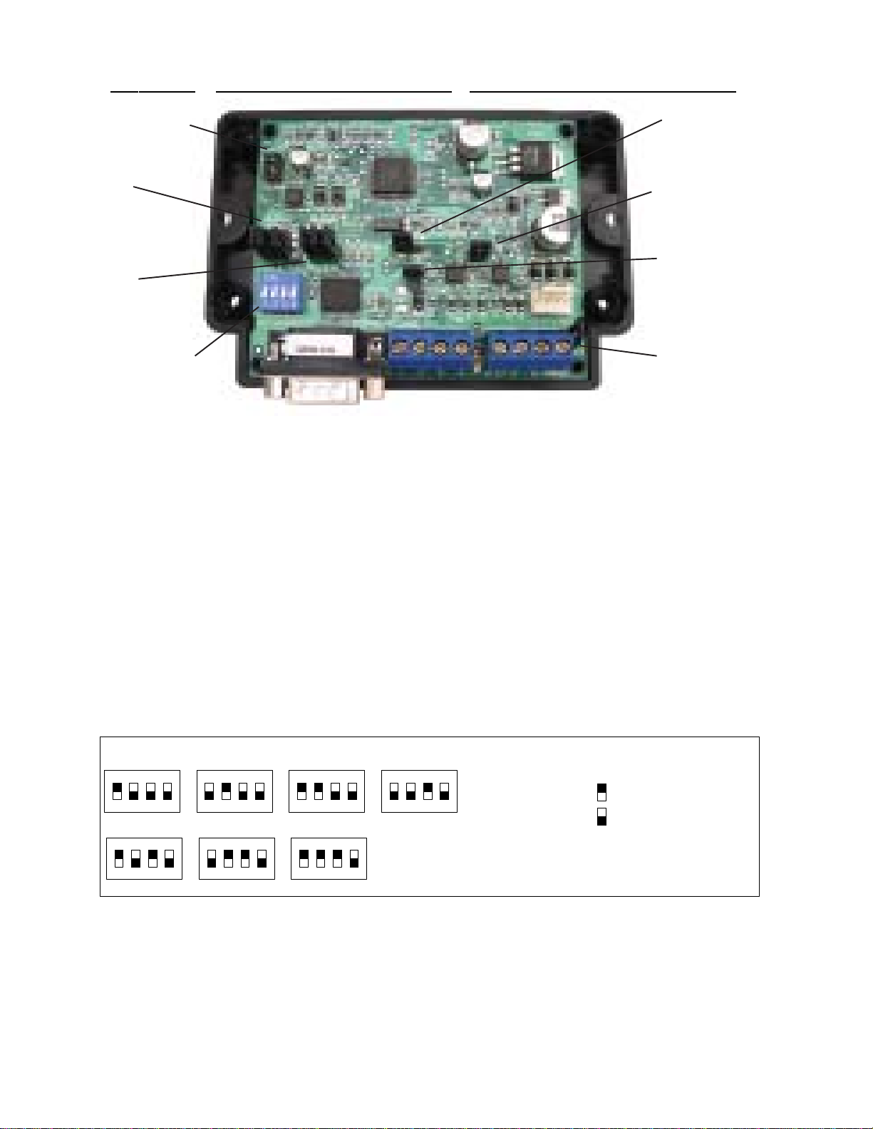
RS-232 (DB9) 9 Pin
Partner Port
INSTALLUNIT * SETADDRESSAND OPTION JUMPERS * ACTIVATE M1 BUS ENROLLMENT PROCESS
RS-485
M1 Data Bus
RS-485
Partner Port
Data Bus
Address
Switches
Jumpers
S1,S2,S3 select
BAUD rate
Jumpers
S4,S5,S6,S7,S8
select Interface
MODE
J1 -Factory
Use ONLY! JP3 - Jumper selects
between RS-232 or
RS-485
JP5 - Jumper Selects
+12VDC to DB9 Pin 4
(MUST be in-place for
HAI Thermostats)
JP1 - Jumper selects
termination of M1
RS-485 Data Bus
JP2 - Jumper selects
termination of
other Mfg. RS-485
Table 1: Data Bus Address Switch Settings
ON
1 2 3 4
ON
1 2 3 4
ON
1 2 3 4
ON
1 2 3 4
Address 1
ON
1 2 3 4
ON
1 2 3 4
ON
1 2 3 4
Address 2 Address 3 Address 4
Address 5 Address 6 Address 7
LEGEND
ON
OFF
M1XSP Data Bus Terminating Jumper
JP1 Used to engage a 120 Ohm resistor for
terminating the M1 RS-485 Data Bus. See
Data bus wiring instructions before use.
For an M1XSP the only valid Data Bus
Addresses are 1 thru 7 since the max.
number of M1XSPs is 7.
Page3 M1XSP Supplementary Instructions and Release Notes
VERY IMPORTANT!
The control uses a RS-485 “differential” data bus operating at 38,400 bits per second. This is relatively high speed by industry standards
and ensures fast, accurate communications. EOL data bus terminating resistors are strongly suggested to eliminate the possibility of
reflection errors due to varying cable lengths. Every device; keypad, expander, etc. and the control has a built-in bus terminating resistor
(120 Ohm) which can be activated via a 2 pin jumper (2 Gold Pins). Two black shorting caps are included in the hardware pack. When one
of the shorting caps is placed on the two gold pins, it activates the 120 Ohm terminating resistor across Data Lines A & B. Terminating
resistors are marked JP2 on the keypads and JP1 on the expanders. From the factory, no terminating resistors are installed (activated).
WARNING! The RS-485 Data Bus must NEVER have more than 2 terminating resistors header/jumpers installed.
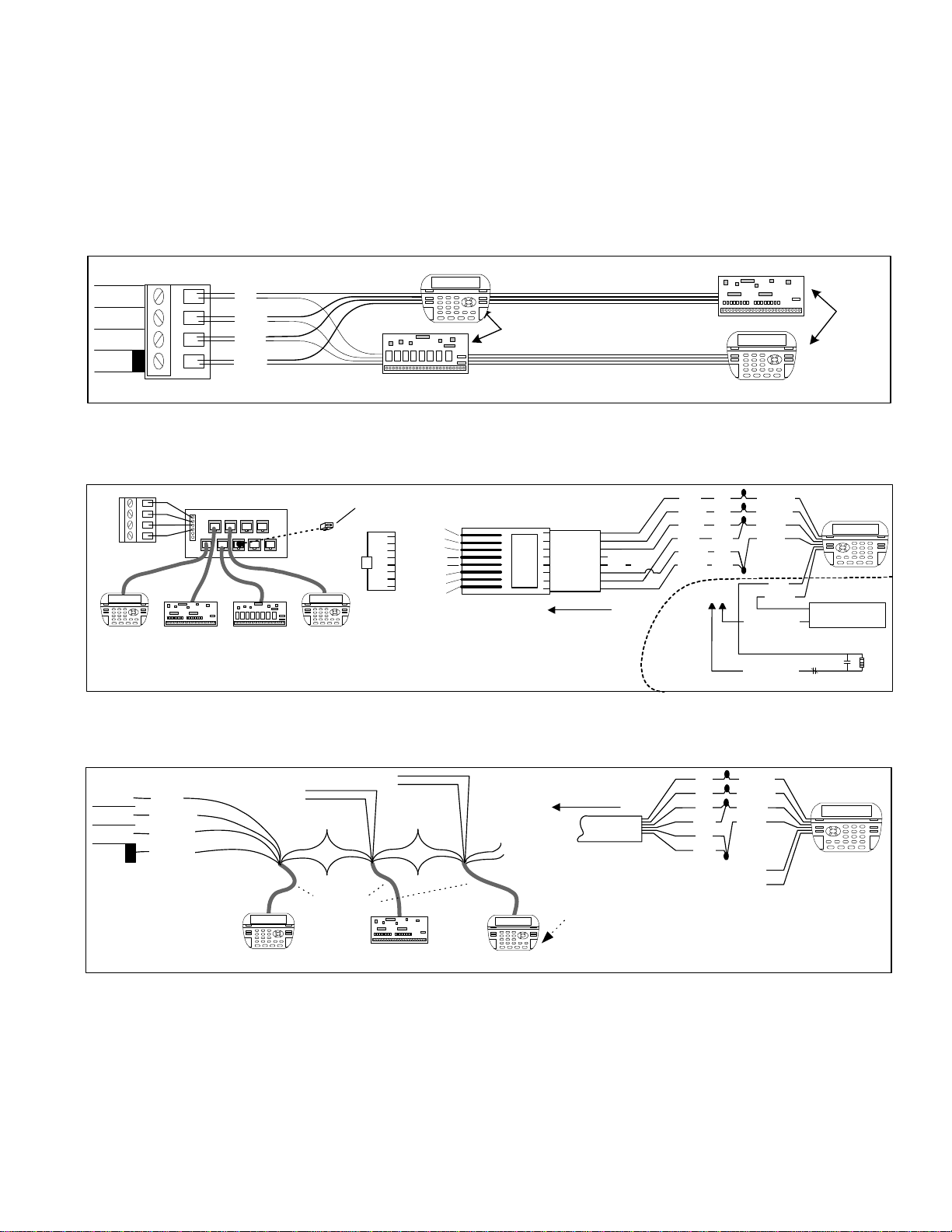
The M1 should have no more than 2 home run cables but devices can be daisy chained along each. The last device on each home run
SHOULD be terminated via the gold 2 pin terminating header/jumper. Placing a shorting cap on the pins will engage a 120 Ohm resistor across
data lines A & B. If there is only 1 data bus home run cable then place shorting cap on JP3 of Main Board. See other hookups below.
The optional ELK-M1DBH † Data Bus Hub is suggested if the job must have more than 2 home runs. The M1DBH accepts CAT5 or CAT6 cable
with RJ45 plugs. It keeps wires more organized while also providing easy bus termination. Essentially, the M1DBH circuit board daisy chains
the devices by series connecting the DATA lines A & B. An plug-in RJ45 terminator is supplied for use in the first unused jack.
Another option for wiring multiple home runs is with 6 conductor cable. This allows devices to daisy chained by making an in and out
connection, basically a 3 way splice of the data A (Green)wire to 2 wires of the 6 conductor cable (designated A and A1). Do the same for the
data B (White) wire. At the control splice the A1 and B1 wires to the A and B wires going to the next device. Terminate the last wired device
and the control JP3 ONLY! The data wires will be in series, but the POS (+) and Neg (-) power wires should be parallel wired to the +VKP and
Neg terminals or to an auxiliary Power Supply if the combined current draw exceeds the rated current available from the Control.
BLACK
WHITE
GREEN
RS-485 Data Bus (Max. length is 4000 ft.
Max. bus devices vary by control.)
RED
Jumper
Terminate
these two
devices.
DO NOT Jumper
Terminate these devices.
Keypad 1 Data Bus Devices e.g. Keypads, Expanders
Keypad 3
Daisy Chain Connection of Data Bus Devices Using Two (2) Home Run Cables
+VKP
DATA B
DATA A
NEG
RS-485 DATA BUS
Install Teminating
Jumper on this last
device AND on the
control JP3.
6 conductor cable
DATA
A1 A
B1 B
DATA
A1 A
B1 B
Optional Output and Zone Input - See Keypad Instructions
Connect each device to the 6 conductor cable as shown above
Daisy Chain Connection of Data Bus Devices Using 6 Conductor Cables
Keypad
RS-485 DATA BUS
+VKP
DATA B
DATA A
NEG
Keypad
RED
GREEN
BLACK
WHITE
To 12VDC
To 12VDC
BLUE
BROWN
6 Wire
Cable
Keypad
RED +12
+BLACK (-)
-
GREEN
WHITE
A
A1
B
B1
TO CONTROL
Keypad
ELK-M1DBH Data Bus Hub †
MountM1DBHinsidecontrol. Connect it to the M1
DataBusterminals usinga4conductorcable.
J2 J4 J6 J8
J1 J3 J5 J7 J9
RJ45 Terminating Plug Insert in first unused jack and terminate the
control at JP3. DO NOT TERMINATE AT ANY OF THE DEVICES!
CAT5 Cables
Daisy Chain Connection using the ELK-M1DBH and CAT5 Cables.
RS-485 DATA BUS
Keypad
Refer to
Keypad
Instructions
for more info
about Output
and Zone Input
+
-
A
A1
B
B1
TO CONTROL
8 - Brown
7 - Wht/Brn
6 - Orange
5 - Wht/Blue
4 - Blue
3 - Wht/Org
2 - Green
1 - Wht/Grn Pin1
RJ45 Plug Blue pair
is unused
COLOR CODE for CAT5 or CAT6 Data Bus Cable
to RJ45 Plugs for ELK-M1DBH Data Bus Hub.
Pin1
Front
view
Optional programmable Zone Input
Optional programmable Output
-
+
N.C. N.O. 2200
Ohm
EOL
To BLACK (Neg)
To BLACK (Neg)
Wht/Blue
Brown
Wht/Brn
Orange
Wht/Org
Green
Blue Wht/Grn
RED +12V
BLACK (-)
GREEN
WHITE
BROWN
BLUE
Keypad
CAT5
or
CAT6
Cable To
+ 12V Load (50mA max)
I.E. LED, Relay
+ VKP
DATA A
DATA B
NEG
ELK-M1 Data Bus E.O.L. Termination

Page4 M1XSP Supplementary Instructions and Release Notes
INSTEON ** Lighting Control ONLY **
INSTEON - INSTEON utilizes Powerline Communications (PLC) technology. Numerous device types are available; such as:
Light Switches, Lamp Modules, Applicance Modules, Keypad Controllers, etc. A unique feature of INSTEON is the availability of
RF signal enhancers or "Bridges" that can extend signal range as well as provide power line signal coupling.
IMPORTANT! There are 2 methods for interfacing INSTEON with an M1 Control.
Carefully read and understand the following before proceeding.
Method 1 is to use an ISY Controller from Universal Devices Inc. to connect with a INSTEON Powerlinc Modem.
This is a popular and often recommended method as it does not require an ELK-M1XSP AT ALL!!
The ISY connects via IP (LAN) to the M1Control using the Elk M1XEP Ethernet Adapter. Again, no ELK-M1XSP required! The
reason this method is so popular is that it provides a more powerful interface with INSTEON, including Computer setup and
management of the devices in an easy to use Graphical User environment
Method 2 is to use an ELK-M1XSP Serial Interface to connect with an INSTEON Powerlinc Modem. See below.
Integration with INSTEON using an M1XSP:
Using the M1XSP an M1 can support up to 192 individually addressable INSTEON Devices and up to 63 Scenes or Groups.
Individual addresses 1-192 are mapped into the M1 architecture as lighting devices 1 to 192. Groups 1-63 are mapped in as
lighting devices 193-255. For example, to turn on INSTEON Group 1 it would be necessary to turn on M1 Lighting device 193.
An attached chart outlines the M1 Lighting devices and their corresponding INSTEON devices.
Limitations with the M1XSP: (With no "third party" hardware/software the following limitations apply)
- INSTEON devices can only be "linked" (learned) into the M1XSP starting at M1 Lighting device 001 (A1). In other words,
there is no way to have devices start at a specific location.
- INSTEON devices cannot be removed or re-arranged individually. If it becomes necessary to remove or re-arrange any
linked devices the entire memory must be cleared and all devices re-linked (learned) again.
- Once an M1XSP has been linked with INSTEON devices, any updating to the firmware in that M1XSP will cause all memory
of linked addresses to be erased, requiring all devices to be re-linked (learned) again.
- INSTEON devices do not initiate a report of their dim level status to the M1. However, they can initiate reports of their full ON
or full OFF status changes. Refer to the section titled "Load Status Communications".
- The M1XSP is capable of sending commands to Groups 1 thru 62, but only if you have a way to setup the groups.
A third party hardware/software interface like the Universal Devices Ins. (ISY99) does not have the above limitations.
Setting up the M1XSP and the M1 to communicate with INSTEON
Componentsrequired:
- ELK-M1 or ELK-M1EZ8 Controller.
- ELK-M1XSP Serial Port Expander. The M1XSP must be flashed with firmware version 50.x.x to support INSTEON
- INSTEON Powerlinc Modem
- One or more INSTEON lighting devices and/or switches.
1. Install the ELK-M1XSP and set its data bus address per instructions on page 2.
2. Set the M1XSP MODE and BAUD jumpers as follows:
S1=1 Is the recommended position. Setting this jumper temporarily to “0” is useful for erasing the INSTEON IDs from
the M1XSP memory. See ERASING INSTEON IDs.
S2=1 Is the recommended position. Do NOT set this jumper to a “0”.
S3=1 Is the recommended position. Setting this jumper to “0” enables polling of the INSTEON network for device
status. Unfortunately this places a heavy burden on the network and is not generally recommended.
S4=1 Is the recommended position. NOTE: Some M1XSPs don’t have this jumper at all.
S5=0 Is the recommended position. This reserves M1 Lighting devices 193-254 for use with INSTEON Groups 1-63.
Setting this jumper to “1” allows M1 Lighting device 193-254 for use with X-10 device codes M01 to P14.
S6=1 Normal position for this jumper. Do NOT set this jumper to a “0”.
S7=0 Normal position for this jumper is “0” which selects compatibilty with the INSTEON Powerlinc Modem. An older
and now discontinued Powerlinc Modem required this jumper to be set to a 1.
S8=1 Normal position for this jumper.
3. Set Jumper JP3 to the “232” position. If there is a shorting Jumper plug on JP5 then remove it and discard.
4. Connect a 9-pin serial cable between the M1XSP and serial connector on the Powerlinc Modem.
5. Power up all the devices and enroll the M1XSP into the M1. VERY IMPORTANT!

Page5 M1XSP Supplementary Instructions and Release Notes
6. Update the firmware in the M1XSP to version 50.1.4 (or the latest 50.x.x version). Download from the Elk website.
7. Use the ELK-RP Software to program the M1 Lighting device attributes for devices 1 through 192 as:
Format = Serial Expander, Type = Dimmer (Type may alternately be On/Off Switch if device does not support dimming).
The first 192 M1 lighting devices may now be "linked" to INSTEON individual addresses.
8. Program the attributes for Lighting devices 193 through 254 as:
Format = Serial Expander, Type = On/Off Switch These 62 lighting devices can be used to control INSTEON Groups.
9. Program the attributes for Lighting devices 255 and 256 as:
Format = Serial Expander, Type = On/Off Switch. Device 255 is reserved for future use. Device 256 is useful for remotely
starting and ending the INSTEON "linking" mode. Program the name for device 256 as: INSTEON LinkMode. Manually
turning device 256 to ON begins the linking mode. Manually turning device 256 to OFF ends then linking mode.
Programming and Linking INSTEON Modules into the M1XSP:
Each INSTEON device has an unique Address ID hardcoded into it. E.G. 00.42.12 Before the M1XSP can send commands to
INSTEON devices it must acquire their IDs. This is done by putting both the M1XSP and INSTEON PLM Interface into “linking"
mode. During the linking mode each device ID will become mapped to an M1 Lighting Device location in the exact order in
which it was linked. I.E. The first linked device will be mapped as M1 Lighting device 1 (A1), the second is 2 (A2), etc. NOTE:
It is not possible to start INSTEON devices at a chose location. This is only possible with 3rd party, separetely puchases
hardware/software from such companies as ISY and Powerhome.
1. To start the linking mode:
a. From the M1 Keypad press the ELK key followed by the Right arrow key. 1-View/Control Automation Fncts.
b. Press the 2 key followed by the right arrow key. 2-Lighting
c. Advance to M1 Light number 256 by entering 2 - 5 - 6. Light 256 should be labeled INSTEON LinkMode.
d. Turn ON Light 256 by pressing the pound (#) key. The M1XSP will then send a serial command to the M1XSP and
PLM Interface and instruct it to begin a 4 minute linking period.
The first device must be linked during this 4 minute time period.
2. Press & hold the link mechanism (LampLinc "SET" button / SwitchLinc "PADDLE") on the INSTEON device to be linked.
NOTE: The 4 minute time period will automatically restart each time a device is linked. At this point it is important to
work quickly so that the 4 minute timer does not expire. If the timer does expire it will be necessary to repeat step
1d and restart the timer before proceeding with any additional linking.
3. The light "LOAD" being controlled should flash once or twice as indication that it has become linked.
NOTE: The M1XSP status LED should flash ON 3 times and then OFF for 2 seconds at it receives the linking from each
INSTEON device. This blink cadence continues until the linking process is manually ended by step 8. **
4. Release the link mechanism. The LED on the device will return to flashing as an indication it is still in the link mode.
5. This step is very important! With the LED on the device still flashing, momentarily tap the the link mechanism once and
verify that the LED stops flashing. This stops the link mode for this device. Be sure the LED has stopped flashing or else
the device will remain in the link mode causing it to be cross linked with future linked devices.
6. Repeat steps 2 thru 5 for each INSTEON device to be learned. Each time this is done, the device will be linked to the next
incremental M1 Lighting device number (002, 003, 004, etc.). A written record should be kept for future recall.
7. Also important! To end the linking process... From the M1 Keypad access the lighting menu just as you did in Step 1,
only this time Turn OFF Light device 256 by pressing the pound (#) key. (Pound toggles between On and Off) Ending the
linking mode will result in the LED on the M1XSP returning to its normal status blink.
8. Test the operation of each light from the ELK-M1 Keypad utilizing the lighting control menu.
** Optional: You may elect to end the linking process after each new device (using step 5) just so the next linked device
will be visually confirmed by the start of the special blink process of the M1XSP. Keep in mind if you elect to do this, the
linking process must then be restarted (using step 2) prior to proceeding to the next device.

Page6 M1XSP Supplementary Instructions and Release Notes
Factory Defaulting INSTEON Devices
During installation or troubleshooting it may be necessary to factory default one or more devices. For example; multiple
devices may inadvertently become cross-linked together, making them turn on together when they should be separate. This
is caused by accidentally linking one device while another device is still in the link mode. Consult the instructions that came
with the device for steps on factory defaulting, including possibly the INSTEON PLM Interface.
Adding (linking) new or additional INSTEON devices at a later date:
Additional devices can be added "linked" at any time by performing the previous steps. The newly linked device(s) will be
associated to the M1 starting with the first empty lighting device locations. The maximum number of devices is 192.
Erasing (unlinking) INSTEON IDs from the M1XSP
Should it ever be necessary to erase the linked INSTEON IDs from the M1XSP memory do the following:
1. Power down the M1XSP
2. Set Jumper S1 = "0" (down)
3. Power up the M1XSP and wait 5 seconds.
4. Power down the M1XSP.
5. Set Jumper S1 = "1" (up) and reapply power to the M1XSP.
NOTE: ALL linked devices are now permanently erased. It is not possible to erase (unlink) individual devices.
Grouping:
Lighting devices 193 to 254 are mapped to control INSTEON “Groups” 1 to 62. Unfortunately, while the M1XSP is capable of
sending INSTEON group commands, only special “third party” hardware/software products are capable of setting up
INSTEON devices into groups. Without this the M1 can only utilize group #1. To setup Group 1 you have to manually place the
INSTEON PLM or PLC Interface into the linking mode and then press the Link mode on the INSTEON device, repeating the
whole process for each device to be included into Group 1. M1 can then controll Group 1 by turning lighting device 193 On/Off.
Operating BOTH INSTEON and X-10 devices:
It is possible for the M1XSP to communicate with both INSTEON and regular X-10 devices via the PLM Interface. Essentially,
on activation of a M1Lighting command the M1XSP (with 50.x.x INSTEON Firmware) will send INSTEON commands for the
lighting device numbers that have an INSTEON linked address, and it will send X-10 commands for the lighting devices that
do not have an INSTEON "linked" address. This helps eliminate the need for a separate X-10 PSC05 or TW523 Interface.
The limitations are this: No X-10 devices should have a House/Unit code that conflicts with any present or future linked
INSTEON device locations. INSTEON device linking ALWAYS begins at M1 Lighting device 1 (A01) and ENDS at 192 (L16).
When setting the House and Unit codes for X-10 devices we recommend NOT using any of the low range numbers.
Special Option - Jumper S5
With the INSTEON version of the M1XSP in default settings no X-10 House or Unit codes can be programmed in the M1
Lighting device locations 193 (M1) to 256 (P16). This is because these locations are reserved for INSTEON Groups and
special commands. But there is a special option (selected by Jumper S5) that will convert this range of device numbers
from INSTEON Groups to X-10. See notes below.
Reminder: M1 Lighting devices start at 1 (A01) and go up to 256 (P16). See the chart on the next page.
N1. M1XSP Jumper S5 = 0 (factory setting) - The M1XSP supports 62 INSTEON Groups mapped as M1 Lighting device
locations 192 to 254 . It cannot support any X-10 devices using a House/Unit code of M01 or above.
N2. M1XSP Jumper S5 = 1 This will disable INSTEON groups and permit X-10 House/Unit codes to occupy M1 Lighting
device locatons 192 (M01) to 254 (P14). INSTEON Groups are disabled when S5 = 1.
N3. Please note that INSTEON RF Signal Enhancers DO NOT provide phase bridging for X-10 transmissions, nor do they
improve or extend the range of X-10 transmissions. A X-10 bridge/coupler is still required for this purpose.
N4. When controlling INSTEON together with X-10 through the PLM Interface and the ELK-M1XSP it is important to
understand that all M1 Lighting Devices should be set as ”Serial Expander" regardless of whether they are INSTEON
or X-10. Do not set the Option box, but be sure to set the Format, Type, Show, and to program an applicable Name.
N5. Transmitted X-10 commands are limited to On, Off, and Preset Dim (provided the X-10 devices support preset).
Received X-10 commands passed from the INSTEON Interface to the M1XSP are limited to On and Off states ONLY.
Load Status Communications:
INSTEON devices can send their On or OFF status to the M1 when a User turns the load On or Off. However, In order for Load
Status "On or Off" tracking to be enabled, the LampLinc or SwitchLinc devices must have the Interface's address linked into
their database. To do this, activate linking mode at the LampLinc or SwitchLinc by pressing and holding the set button or
paddle for 10 seconds. The LED will blink on the LampLinc or SwitchLinc. Now press and hold the set button on the
INSTEON Interface for 10 seconds. The LED on the LampLinc or SwitchLinc should go solid to indicate they have been
successfully linked to the Interface.
NOTE: INSTEON devices DO NOT initiate a report of their dim level status to the M1 when a device is changed by the User
to a new level (eg:100% to 50%), only On or Off. However, the latest M1XSP firmware does send a command to request
the level of a switch whenever it hears a switch has been pressed.

Page7 M1XSP Supplementary Instructions and Release Notes
INSTEON
Device 1
Device 2
Device 3
Device 4
Device 5
Device 6
Device 7
Device 8
Device 9
Device 10
Device 11
Device 12
Device 13
Device 14
Device 15
Device 16
Device 17
Device 18
Device 19
Device 20
Device 21
Device 22
Device 23
Device 24
Device 25
Device 26
Device 27
Device 28
Device 29
Device 30
Device 31
Device 32
Device 33
Device 34
Device 35
Device 36
Device 37
Device 38
Device 39
Device 40
Device 41
Device 42
Device 43
Device 44
Device 45
Device 46
Device 47
Device 48
Device 49
Device 50
Device 51
Device 52
Device 53
Device 54
Device 55
Device 56
Device 57
Device 58
Device 59
Device 60
Device 61
Device 62
Device 63
Device 64
ELK
Light
Device #
1
2
3
4
5
6
7
8
9
10
11
12
13
14
15
16
17
18
19
20
21
22
23
24
25
26
27
28
29
30
31
32
33
34
35
36
37
38
39
40
41
42
43
44
45
46
47
48
49
50
51
52
53
54
55
56
57
58
59
60
61
62
63
64
PLC
(X-10)
Ref.
A01
A02
A03
A04
A05
A06
A07
A08
A09
A10
A11
A12
A13
A14
A15
A16
B01
B02
B03
B04
B05
B06
B07
B08
B09
B10
B11
B12
B13
B14
B15
B16
C01
C02
C03
C04
C05
C06
C07
C08
C09
C10
C11
C12
C13
C14
C15
C16
D01
D02
D03
D04
D05
D06
D07
D08
D09
D10
D11
D12
D13
D14
D15
D16
INSTEON
Device 65
Device 66
Device 67
Device 68
Device 69
Device 70
Device 71
Device 72
Device 73
Device 74
Device 75
Device 76
Device 77
Device 78
Device 79
Device 80
Device 81
Device 82
Device 83
Device 84
Device 85
Device 86
Device 87
Device 88
Device 89
Device 90
Device 91
Device 92
Device 93
Device 94
Device 95
Device 96
Device 97
Device 98
Device 99
Device 100
Device 101
Device 102
Device 103
Device 104
Device 105
Device 106
Device 107
Device 108
Device 109
Device 110
Device 111
Device 112
Device 113
Device 114
Device 115
Device 116
Device 117
Device 118
Device 119
Device 120
Device 121
Device 122
Device 123
Device 124
Device 125
Device 126
Device 127
Device 128
ELK
Light
Device #
65
66
67
68
69
70
71
72
73
74
75
76
77
78
79
80
81
82
83
84
85
86
87
88
89
90
91
92
93
94
95
96
97
98
99
100
101
102
103
104
105
106
107
108
109
110
111
112
113
114
115
116
117
118
119
120
121
122
123
124
125
126
127
128
PLC
(X-10)
Ref.
E01
E02
E03
E04
E05
E06
E07
E08
E09
E10
E11
E12
E13
E14
E15
E16
F01
F02
F03
F04
F05
F06
F07
F08
F09
F10
F11
F12
F13
F14
F15
F16
G01
G02
G03
G04
G05
G06
G07
G08
G09
G10
G11
G12
G13
G14
G15
G16
H01
H02
H03
H04
H05
H06
H07
H08
H09
H10
H11
H12
H13
H14
H15
H16
ELK
Light
Device #
129
130
131
132
133
134
135
136
137
138
139
140
141
142
143
144
145
146
147
148
149
150
151
152
153
154
155
156
157
158
159
160
161
162
163
164
165
166
167
168
169
170
171
172
173
174
175
176
177
178
179
180
181
182
183
184
185
186
187
188
189
190
191
192
PLC
(X-10)
Ref.
I01
I02
I03
I04
I05
I06
I07
I08
I09
I10
I11
I12
I13
I14
I15
I16
J01
J02
J03
J04
J05
J06
J07
J08
J09
J10
J11
J12
J13
J14
J15
J16
K01
K02
K03
K04
K05
K06
K07
K08
K09
K10
K11
K12
K13
K14
K15
K16
L01
L02
L03
L04
L05
L06
L07
L08
L09
L10
L11
L12
L13
L14
L15
L16
ELK
Light
Device #
193
194
195
196
197
198
199
200
201
202
203
204
205
206
207
208
209
210
211
212
213
214
215
216
217
218
219
220
221
222
223
224
225
226
227
228
229
230
231
232
233
234
235
236
237
238
239
240
241
242
243
244
245
246
247
248
249
250
251
252
253
254
255
256
INSTEON
Device 129
Device 130
Device 131
Device 132
Device 133
Device 134
Device 135
Device 136
Device 137
Device 138
Device 139
Device 140
Device 141
Device 142
Device 143
Device 144
Device 145
Device 146
Device 147
Device 148
Device 149
Device 150
Device 151
Device 152
Device 153
Device 154
Device 155
Device 156
Device 157
Device 158
Device 159
Device 160
Device 161
Device 162
Device 163
Device 164
Device 165
Device 166
Device 167
Device 168
Device 169
Device 170
Device 171
Device 172
Device 173
Device 174
Device 175
Device 176
Device 177
Device 178
Device 179
Device 180
Device 181
Device 182
Device 183
Device 184
Device 185
Device 186
Device 187
Device 188
Device 189
Device 190
Device 191
Device 192
INSTEON
Group 01
Group 02
Group 03
Group 04
Group 05
Group 06
Group 07
Group 08
Group 09
Group 10
Group 11
Group 12
Group 13
Group 14
Group 15
Group 16
Group 17
Group 18
Group 19
Group 20
Group 21
Group 22
Group 23
Group 24
Group 25
Group 26
Group 27
Group 28
Group 29
Group 30
Group 31
Group 32
Group 33
Group 34
Group 35
Group 36
Group 37
Group 38
Group 39
Group 40
Group 41
Group 42
Group 43
Group 44
Group 45
Group 46
Group 47
Group 48
Group 49
Group 50
Group 51
Group 52
Group 53
Group 54
Group 55
Group 56
Group 57
Group 58
Group 59
Group 60
Group 61
Group 62
Reserved for future use
Linking Mode (On/Off)
PLC
(X-10)
Ref.
M01
M02
M03
M04
M05
M06
M07
M08
M09
M10
M11
M12
M13
M14
M15
M16
N01
N02
N03
N04
N05
N06
N07
N08
N09
N10
N11
N12
N13
N14
N15
N16
O01
O02
O03
O04
O05
O06
O07
O08
O09
O10
O11
O12
O13
O14
O15
016
P01
P02
P03
P04
P05
P06
P07
P08
P09
P10
P11
P12
P13
P14
P15
P16
The PLC column is for reference only.
M1 Lighting Devices Mapped to INSTEON
INSTEON-(continued)

Page8 M1XSP Supplementary Instructions and Release Notes
Changes effective with this new application firmware:
NOTE: Updating will ERASE ALL linked Insteon devices!
1. Found a reported problem of the M1XSP occasionally defaulting itself (erasing all enrolled devices) upon power up.
Added a 1 second debounce timer upon power-up before reading the state of Jumper S1.
2. New feature - It is now possible to tell the M1XSP to totally ignore X-10 type commands heard from the M1 or from the
Insteon PLC by setting Jumper S8 to “0”. I.E. X-10 can still travel on the X-10 connector located on the M1G board while
Insteon commands travel on the M1XSP without clashing or inteferring with one another.
Version 50.0.28 released June 2, 2008
The M1XSP stores it’s operating firmware in “Flash” memory. This state-of-the-art memory allows electronic field updates
and eliminates the old fashion method of changing IC chips or shipping boards back to the factory. As new firmware updates
become available, they will be posted on ELK’s website found at www.elkproducts.com. NOTE: Firmware updating can only
be done through the M1 Control using a Direct to PC Com port connection or an optional Ethernet Network connection.
Dial-up connections cannot be used to perform firmware updates.
How to Update:
1. Physically connect the Computer and Control using either the RS-232 Serial Port 0 or the M1XEP Ethernet Interface.
2. Open ElkRP and the account belonging to the control. Click on the Connection menu icon and establish a connection.
Use either the Direct using Com_ OR Network options.
3. On the Send/Rcv menu icon there is a selection that allows the firmware to be updated.
4. Select the device to be updated. In this case it is a Serial Expander. Select the update firmware option.
5. Display will show: Device name, current Firmware, Hardware, and Bootware version, and a pull down window for selecting
the update firmware. NOTE: All update (.bin) files downloaded or received should be stored in a directory on your
computer. Refer to the Options tab under the Setup menu in RP. It will indicate what directory is used for the update files.
6. Click on the check box for “Update”. If “Reprogram” or “Rollback” is displayed the firmware file is the same as OR older
that what is in the control. Reprogramming with the same firmware is a waste of time but was included for factory testing
purposes. Rollback is not recommended except under the guidance of Elk Technical Support.
Updating/Replacing Firmware in the ELK-M1XSP
Firmware Release Notes
Version 50.1.4 released Jan 20, 2009
Changes effective with this new application firmware:
NOTE: Updating will ERASE ALL linked Insteon devices!
1. Found and resolved an issue when using a rule to turn on a light for a timed period using the Insteon PowerLinc MODEM.
The timer associated with the light would be erased, resulting in the light never turning off.
IMPORTANT REMINDERABOUTTHE POWERLINC MODEM:
For persons using PowerHome’s “Elk Insteon Device Loader” there is a new version required
for use with this firmware and the Powerlinc Modem (PLM). Refer to Elk’s website
under Partner Manufacturers page for a link to the PowerHome software.
Version 50.1.2 released Jan 5, 2008
Changes effective with this new application firmware:
NOTE: Updating will ERASE ALL linked Insteon devices!
1. Added support for the new INSTEON PowerLinc Modem which replaced the now obsolete older PLC interface.
For at least the time being this version continues to provide support for the obsolete PLC interface.

Page9 M1XSP Supplementary Instructions and Release Notes
Changes effective with this new application firmware:
NOTE: Updating will ERASE ALL linked Insteon devices!
1. Polling for status after a manual switch press - Added a new routine to make the M1XSP poll a device if it detects release of
the on or off switch. This should improve the ability for the M1 to get the level (instead of just on and off) of the light after a
local switch press.
2. Polling for status after a group command - Added a new routine to make the M1XSP poll devices that were controlled by the
group command AS LONG AS the controller sends the group cleanup messages. CAUTION! Not all controllers send the
cleanup messages. Also, if another command needs to be sent the cleanup messages are generally discarded.
3. Reports of the M1XSP losing the programmed Insteon ID numbers after a power reset - A modification has been made to
the flash memory write routine to provide additional protection against this possibility.
4. Reports of lights changing levels a short period after the light is manually changed - It was found that this could be caused
after the PLC receives a group command. A modification has been made to the way the data is parsed which should
resolve this possibility.
Version 50.0.26 released Mar 9, 2007
Changes effective with this new application firmware:
NOTE: Updating will ERASE ALL linked Insteon devices!
1. Added support for “Powerhome” software (available from: http://www.myx10.com). Powerhome can now be used for
programming and managing Insteon address IDs in the M1XSP. This includes: reading Insteon address IDs from the
M1XSP into the PC software, and reading (discovery) of the M1 Lighting device names (text) which are stored inside the
M1 by way of the M1XSP. This process requires a direct serial port connection directly from the PC to the M1XSP,
temporarily disconnecting the M1XSP from the Insteon Powerlinc interface.
2. Added a text string “LINK^M” to be transmitted from the M1XSP to the M1 whenever the link mode is activated (lighting
device 256 ON) and a valid link is received from the Insteon Powerlinc interface. This is helpful during the manual linking
mode. An M1 rule can be written to blink an output, make an announcement, etc. whenever a new device is linked into the
Insteon Powerlinc interface. Be certain to program this exact text into the ElkRP Automation/Text string locations in order
for it to be available in the rules engine.
3. Improved the receiving of certain commands from the Powerlinc interface during the manual link mode.
Version 50.0.22 released June 23, 2006
Other manuals for M1XSP
1
Table of contents


