Elkay ECH82WR Installation manual

1000004317 (Rev. A - 08/2017)
ECH8_2NWR
PAGE 1
220V Refrigeration Package
Installation / Care / Use Manual
Model : ECH82WR
Original Instructions
Description
Remote Water Chillers are designed to reduce the temperature of potable water that is routed through the water chiller. This chiller is meant to be
installed in a properly ventilated, non-visible location.
Ratings
• Electrical: 220VAC, 50Hz, (See nameplate for Amperage), 1 phase.
• Ambient Air Temperature: 50-100.4 °F (10-38 °C).
• Water Pressure: 20-100 psig (0.14-0.69 MPa).
• Maximum Water Temperature: 90 °F (32 °C).
• Refrigerant: HFC-R134a
• Ingress Protection: IP2x
• For Indoor Commercial Use only.
Legend
A = 1/4" (6.4mm) O.D. Tube Water Outlet
B = 3/8" (9.5mm) O.D. Tube Water Inlet
C = Temperature Adjustment
D = Electrical Inlet
Safety
DANGER
• Please read these instructions completely before starting the installation or performing any service. Failure to follow the instructions and safety
precautions in this manual can result in serious injury or death.
• After installation, keep these instructions in a safe location for future reference.
• Electric supply must be identical in voltage, cycle, and phase to that specied on nameplate.
• Electrical supply must have Ground Fault Circuit Interrupter (GFCI) protection.
• A means for disconnecting electrical supply to the unit must be incorporated in the xed wiring in accordance with wiring rules. This is to allow
electrical disconnection of the unit from electrical supply after installation.
WARNING
• For use with clean, clear potable drinking water only. Do not use with water that is microbiologically unsafe or of unknown quality without
adequate disinfection before the system.
• Installation and connection to water and electrical mains must be in compliance with local and national laws.
• All Installation and Service work must be performed by an authorized service personnel.
CAUTION
• This appliance can be used by children aged from 8 years and above and persons with reduced physical, sensory, or mental capabilities
or lack of experience and knowledge if they have been given supervision or instructions concerning use of the appliance in a safe way and
understand the hazards involved. Children shall not play with the appliance. Cleaning and user maintenance shall not be made by children
without supervision.
• To prevent a metallic taste or increased metal content in the water due to an electrolysis process caused by electrical feedback from the
grounding of electrical equipment to water supply and water waste mains, connect to these mains using non-conductive materials. The provided
solenoid valve regulator assembly meets this requirement.

1000004317 (Rev. A - 08/2017)
ECH8_2NWR
PAGE 2
Installation Steps
1. It is important to insure proper ventilation. When mounting in an
open area, to insure proper ventilation, maintain a 4" (102mm)
clearance from cabinet louvers on each side of cooler. When
mounting unit in a cavity or behind a wall, maintain a minimum
space of 4" (102mm) on each side, 4" (102mm) on the top and
a depth of 12" (305mm).
2. Connecting lines to be made of unplated copper. Thoroughly ush
all lines to remove all foreign matter before connecting to cooler.
3. Connect in-line water strainer(Provided, Item 16) to chiller water
inlet. See Figure 2.
4. Connect in-line water strainer to building supply with a water
shut-off valve (not provided). See Figure 2.
Wiring Instructions
1. Turn off electrical supply to chiller circuit.
2. Remove front panel (Item 10) to gain access to electrical box
using a 5/16" (7.9mm) socket wrench or a athead screwdriver.
3. Rotate fan to insure proper clearance and free fan action.
4. Join electrical wire to unit using 3/8” cable clamp connector or
appropriate conduit connector.
5. Connect ground wire to ground screw (provided).
6. Connect black wire to 230Vac.
7. Connect white wire to Neutral line.
8. Replace front panel (Item 10).
Start-Up
1. Open water shut-off valve
2. Purge air from all water lines by operating bubbler valve of
fountain to which chiller is connected. Steady water stream
assures all air is removed. Check all water connections for
leaks. Fix all leaks before proceeding.
3. Rotate fan to insure proper clearance and free fan action.
4. Turn on electrical supply.
NOTE: WATER FLOW
DIRECTION
BUILDING WATER SUPPLY
WATER SHUT-OFF VALVE
(NOT PROVIDED)
1/4" O.D. TUBE
WATER INLET
FROM CHILLER
3/8" (9.5mm) O.D.
UNPLATED COPPER TUBE
(NOT PROVIDED)
IN-LINE
STRAINER
(PROVIDED)
Figure 2
Figure 1
TUBE IS SECURED
IN POSITION
SIMPLY PUSH IN
TUBE TO ATTACH
PUSH IN COLLET
TO RELEASE TUBE
PUSHING TUBE IN BEFORE
PULLING IT OUT HELPS TO
RELEASE TUBE
Figure 4
ACBD
A = Plug with 7/8" (22.2mm) Hex
B = O-ring
C = Screen
D = Strainer Body with 1" (25.4mm) Hex Figure 3
Installation
For correct and safe installation, please read these instructions completely.
• All Installation work must be performed by an authorized service personnel.
• Disconnect electrical supply serving the Installation area to reduce risk of electrocution.
• Unit not suitable for installations where water jets could be used.
DANGER
WARNING
• Shut off water supply serving the Installation area to reduce risk of water damage.
• Ensure proper ventilation by maintaining clearance from cabinet louvers to wall on each side of Cooler as specied in installation instructions.
• Never wire compressor directly to electrical supply.
• Thoroughly ush all water lines and ttings of all foreign matter before connecting to Cooler.
• Warranty is void if Installation is not made in accordance with current Manufacturing instructions.
CAUTION
• Hose-sets are not to be used for connecting to water mains.
• If inlet pressure is above 100 psig (0.69 MPa), a pressure regulator must be installed in water supply line. Any damage caused by reason of
connecting this product to water supply line pressure outside it’s rated pressure, is not covered by warranty.
• Tools/Items required but not provided:
• Safety Glasses
• Protective Gloves
• 5/16" (7.9mm) Socket Wrench or Flat Head Screwdriver
• Water Shut-off Valve

1000004317 (Rev. A - 08/2017)
ECH8_2NWR
PAGE 3
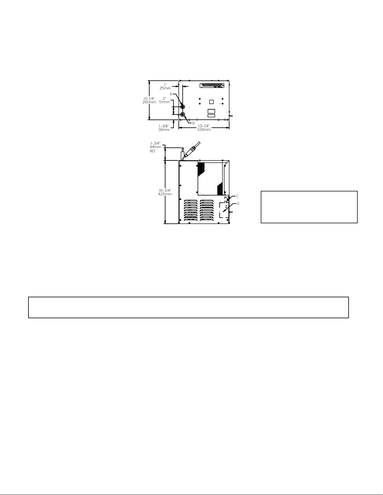
1. Temperature Control: Factory set for 50ºF ± 5º (10ºC ± 2.8º) water under normal conditions. To adjust water temperature, turn off electrical supply,
remove front panel (Item 10) using a 5/16" (7.9mm) socket wrench or at head screwdriver, and turn screw on cold control (Item 9) clockwise for
colder, counter clockwise for warmer.
Service: Adjustments
Service: Inspection/Cleaning
• Inspect Water Chiller twice each year for proper operation and performance.
• Inspection of the unit will require disconnecting electrical supply, removal of panels, etc. and reassembly and return to service practices.
1. Condenser Fan Motor: Conrm condenser fan turns freely. If the condenser fan does not spin freely, have an authorized service personnel replace.
2. Ventilation: Cabinet louvers and condenser ns should be periodically cleaned with a brush, air hose or vacuum cleaner. Cleaning should be done
twice each year or more frequently if needed due to environment. Excess dirt or poor ventilation can cause no cold water and compressor cycling
on the compressor overload protector.
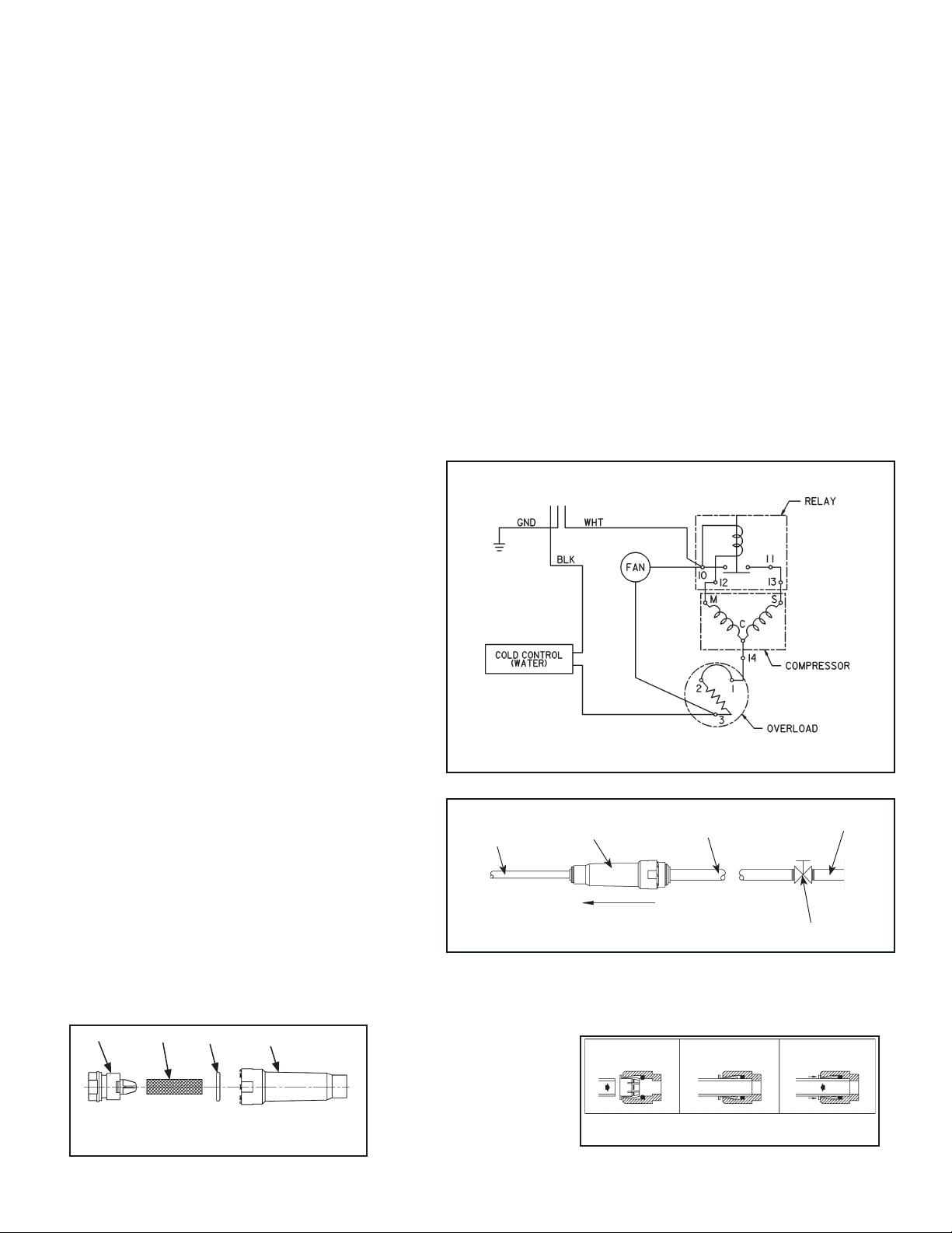
3. Water Flow: Conrm proper water ow. If water ow is slow, inspect lter or inline strainer for restriction. Replace lter cartridge if required. Disassemble
inline strainer and clean if required. See Figure 3.
4. Lubrication: Motors are lifetime lubricated.
5. Actuation of Quick Connect Water Fittings: Cooler is provided with lead-free connectors which utilize an o-ring seal. To remove tubing from the
ttings, relieve water pressure and push in on gray collar while pulling on the tubing. To insert tubing, push tube straight into tting until it reaches a
positive stop, approximately 3/4" (19mm). See Figure 4.
*INCLUDES RELAY & OVERLOAD. IF UNDER WARRANTY, REPLACE
WITH SAME COMPRESSOR USED IN ORIGINAL ASSEMBLY.
NOTE: All correspondence pertaining to any of the above water cooler or
orders for repair parts MUST include model number and serial number of
cooler, name and part number of replacement part.
For Replacement Parts, contact your local distributor or call 1.800.834.4816
Elkay Manufacturing Co. 2222 Camden Court – Oak Brook, IL 60523 U.S.A – 630.574.8484
15
16
4
14
7
6
8,11
13
3
2
10
5
17
12
Service
• Safety Glasses
• Protective gloves
• 5/16” (8mm) Hex Socket or Flathead Screwdriver
For proper and safe servicing, please read these instructions completely.
DANGER
• All Service and Maintenance must be performed by an authorized service personnel.
• Disconnect electrical supply to the unit before any service work to reduce risk of electrocution.
• Shut off water supply serving the unit before any service work to reduce risk of water damage.
CAUTION
• Tools/Items required but not provided, for Servicing:
Replacement Parts: Parts List
ITEM NO. PART NO. DESCRIPTION
1 1000004316 KIT - EVAP REPLACE ASSY
2 28478C CABINET
3 98776C KIT - CONDENSER/DRIER
4 0000000244 KIT - FAN MTR/BLADE/NUT/SHROUD (50Hz)
5 20282C BRACKET - FAN MOUNTING
6 98778C KIT - HEAT EXCHANGER/DRIER
7 66703C DRIER
8 1000002147 COMPRESSOR SERVICE PAK (50Hz)
9 98773C KIT - COLD CONTROL/SCREWS
10 28477C PANEL - FRONT
11 98751C KIT - ELECT/RELAY/COVER/OL (50Hz)
12 98777C KIT - COMPRESSOR MTG HDWE
13 50930C BUMPER
14 27303C BASEPLATE
15 22300C PANEL - REAR
16 1000004069 IN-LINE STRAINER
17 56237C SHROUD
*
16
15
3
5
4
17
9
7
8, 11
12
14
10
6
2
1
13
Table of contents
Popular Fan manuals by other brands

Inspire
Inspire BEACH S 88405684 instruction manual

LUCCI Air
LUCCI Air AIRFUSION BREEZE TRIPOD FAN installation instructions

Inspire
Inspire Wilma Assembly, Use, Maintenance Manual

Vallox
Vallox 90MC Series Operating, maintenance and technical instructions

Clarke
Clarke CAM5002 Operating & maintenance instructions

Maico
Maico EDR 25 Mounting and operating instructions