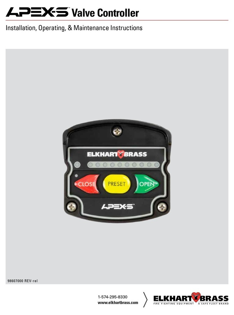
ELKHART BRASS APEX 100 Assembly instructions

98600000 REV-A
APEX 300 Shown
Valve Controller
APEX 100, APEX 200 & APEX 300
Installation, Operating, &
Maintenance Instructions

2
Table of Contents
Introduction ..................................4
Overview ...................................4
Features ....................................4
Specifications ...............................5
General Description............................6
Components ................................6
Controls and Indicators .......................7
Installation ...................................8
Install Valve Controller ........................8
Install Pressure Sensor (APEX 200 and 300).......10
Install Flow Sensor (APEX 300).................12
Electrical Connections .........................18
Initial Setup Adjustments ......................24
Valve Position Calibration ....................24
Display .....................................29
User Settings ................................31
Adjusting User Settings ......................31
Operation ...................................32
Screen Overview ............................32
Event Log . . . . . . . . . . . . . . . . . . . . . . . . . . . . . . . . . . .38
Event Log Functions .........................38
Setup .....................................40
User Access Level............................40
Factory Settings ..............................44
Changing Factory Settings ....................44
Maintenance/Calibration ......................48
Water Flow Rate Calibration (APEX 300) ........48
Pressure Calibration .........................49
Diagnostics .................................51
Diagnostics Tools............................51
Active Error/Warning .........................53
Error/Warning Codes Troubleshooting Table ......54

3
List of Tables
Table 1. Pressure Sensor Output Voltage .........5
Table 2. Error/ Warnings Codes
and Troubleshooting ......................54
List of Figures
Figure 1. Controls and Indicators ...............7
Figure 2. Valve Controller Mounting Dimensions ..9
Figure 3. Pressure Sensor .....................11
Figure 4. Flow Sensor Location Guide ..........13
Figure 5. Saddle Clamp Installation ............15
Figure 6. Weldment Installation ...............17
Figure 7. Control Module Wiring ..............18
Figure 8. Valve Actuator Wiring ...............19
Figure 9. Wiring (Cables and Connectors) .......20
Figure 10. Wiring (Cables and Connectors) ......21
Figure 11. APEX 1:1 Wiring Connections ........22
Figure 12. APEX 2:1 Wiring Connections ........23

4
Introduction
Overview
The electric valve and controller display are designed with precision and ease of
use in mind. Rugged design withstands the demands of outdoor apparatus use.
Modern electronics, display technology and tactile buttons provide enhanced
user experience with intuitive and familiar operation. Monitor the valve position
and sensor readouts on a full-color, high brightness, high contrast Liquid Crystal
Display (LCD). Use keypad buttons to open, close and adjust valve position. Utilize
the built-in graphic menu system to setup, calibrate, customize your settings,
change available options, access usage logs and diagnostic information.
APEX 100 - Valve control with valve position indicator.
APEX 200 - Valve control with valve position indicator and pressure display.
APEX 300 - Valve control with valve position indicator, pressure display and digital
flow display.
Features
Display–3.5" Color LCD Panel with 320x240 Resolution, Sunlight Readable
Keypad–rubberized, large, embossed and color-coded Tactile Buttons (glove friendly)
Programmable Valve Preset Positions
Button actions–Full Open, Full Close
Single or Multiple Flow Rate Calibration Points (APEX300)
Screen Protection–Chemically Strengthened 3 mm Glass Cover (0.12" thick) Provides Impact
Protection and Scratch Resistance
Enclosure– Molded Glass-filled Polymer for Rigidity, Surface Hardness and Strength
Sealed to IP67 Ingress Protection on All Sides
Pressure Vent –Relives Internal Pressure Buildup from Temperature Fluctuations
Visor–Color-coded in 12 Colors to Match Discharges to Valve Controller
Light Sensor–Day/Night Mode for Automatic Screen Brightness Adjustments
Connector– Deutsch Sealed Connectors (Power & CAN data/bus)
USB Port–Type A Port for Firmware Updates, Back-up and Data Retrieval
Power Requirements–9 to 30 VDC; Less than 4 Watts Power Consumption

5
Specifications
Control and Display Module
Supply Voltage: 9—30VDC
Current: 0.5 A - Display Module only.
Dimensions:
Height 5 3/4"
Width 3 3/4"
Depth 2 11/16"
Datalink Interface: CAN Bus
Flow Sensor
Part Number: 71751000
Type: Paddlewheel
Sensor Material: Acetal (Delrin) with Stainless Steel (316) Shaft
Excitation Voltage: 5 VDC
Pressure Sensor
Part Number: 65106000
Pressure Range: 0 - 600 PSI
Proof Pressure: 1200 PSI
Excitation Voltage: 5 VDC
Output Voltage: 0.5 - 4.75 VDC (Refer to Table 1)
Table 1. Pressure Sensor Output Voltage
PRESSURE (PSI) VOLTAGE (VDC)
00.5
100 1.21
150 1.56
200 1.92
250 2.27
300 2.625
600 4.75

6
General Description
Components
The Electric Valve System consists of the following components:
APEX Valve Controller
Pressure Sensor
Paddlewheel Flow Sensor and Mounting Assembly
Valve with E14X (or E16X for EB6D) Actuator
Cables
APEX Valve Controller
The valve control and display module is sealed to an IP67 rating, and has dimensions of
5 3/4 inches high by 3 3/4 inches wide by 2 11/16 inches deep. All controls and indicators are
located on the front of the display module. (Refer to Controls and Indicators.)
Pressure Sensor
The pressure sensor provides a pressure reading to the valve controller. It is mounted on the
downstream side of the discharge valve. The electrical connector is waterproof and molded
into the pressure sensor housing.
Paddlewheel Flow Sensor
The flow sensor provides a discharge flow reading to the valve controller. It is mounted in the
discharge piping. Placement of the sensor in the piping is critical to obtaining accurate flow
rate information; refer to the installation procedures for detailed information on mounting
locations. The electrical connector is waterproof and molded into the flow sensor housing.
Valve with E14X (E16X for EB6D)Actuator
It is installed in the apparatus plumbing and connects to the valve controller. In some
configurations, it will connect with flow and pressure sensors.
Cables
Interconnecting cables are provided. Refer to Electrical Connections (Wiring) section.

7
Figure 1. Controls and Indicators
Controls and Indicators
The display and pushbuttons controls are accessible on the front of the unit.
(Refer to Figure 1.)
Valve Position Indicator
When the valve is fully closed the red closed indicator will be on. The bar graph indicates the
valve position as it moves from closed to fully open.
Valve Control Buttons
Three buttons control the valve motor to open and close the valve. The preset button will set the
valve to a programmed position. Menu button is used for menu functions.
Pressure Display (APEX200/300)
This onscreen pressure gauge will indicate pressure in PSI, kPa, or Bar.
Flow Display (APEX300)
This display will indicate the flow rate in GPM or LPM.
Color-Coded Visor
The Visor helps prevent water and dirt from running down the display. Also can be used to
color code the valve controller to match the corresponding discharge.
WATER FLOW
RATE DISPLAY
VALVE POSITION
BAR GRAPH
VALVE CONTROL
BUTTONS
PRESSURE GAUGE
VALVE CLOSED
INDICATOR
VISOR

8
Installation
The APEX valve controller is compatible with valves used with 1.5 to 8 inch piping.
!
NOTE: Plumbing systems are always unique and may cause small deviations in
the factory calibration. If necessary a calibration procedure can be performed
after installation.
Install Valve Controller
The valve controllers are interchangeable. It is recommended that the calibration be checked
if modules are swapped.
1. Measure and mark mounting location for control module panel cutout and mounting
screw holes. Make sure there is clearance behind the panel for the display and cables
before cutting holes. Refer to Figure 2 for layout and dimensions.
2. Cut out a mounting hole according to the cutout diagram in Figure 2, and drill three
holes (clearance or tapped) for #10 mounting screws.
3. Connect the cables and wires. (Refer to Wiring section.)
4. *Place control module into position and secure with three screws.
Use #10 size, Phillips pan head type screws with a minimum length of 1.25 inch.
!
*NOTE: The Visor must be placed onto the valve controller module housing
prior to inserting mounting screws and attaching to your apparatus.

9
Figure 2. Valve Controller Mounting Dimensions
1 3/8"
7/8"
1 5/16"
1 3/32"
3 3/4"
5 3/4"
Recommended Panel Cutout
NOTE: Page must be printed at 100% or template size will be scaled incorrectly.
#10 clear
(thru-bolt with nut)
or tapped for #10
fasteners, 3x
3 1/16"
4 9/16"
2 7/8"
2 1/2"
R 1/2"
2 3/8"
4 7/8"

10
Install Pressure Sensor (APEX 200 and 300)
The pressure sensor is mounted on the downstream side of the discharge valve.
Pressure sensors are interchangeable. It is recommended that the calibration be checked if
pressure sensors are swapped.
Note: Install the pressure sensor upright so water in the end of the sensor is able to drain
back into the pipe.
1. Screw the sensor into a 1/4-18 NPT hole.
Caution: Do not use the main body that houses the electronics to tighten the pressure sensor.
Damage to the sensor may occur.
2. Tighten the sensor with a 3/4-inch wrench on the lower hex fitting.
3. Connect the pressure sensor cable from the valve actuator to the sensor. (Refer to
Wiring section.)
SPECIFICATIONS
Performance Data
Accuracy RSS
PN 65106000 ±0.25% FS
Thermal Effects
Compensated Range °F (°C) -40 to +221 (-40 to +105)
PN 65106000
Zero/Span Shift %FS/100°F (%FS/100°C)
0.94 (2.0)
for <1000 PSI (60 Bar)
Zero Tolerance
PN 65106000 1% FS for <1000 PSI (60 Bar)
Span Tolerance
PN 65106000 1% FS for <1000 PSI (60 Bar)
Response Time 1ms
Long Term Stability ±0.2% FS/YR Non-Cumulative
Proof Pressure See Table Below
Burst Pressure See Table Below
Fatigue Life Designed for more than 100 M cycles
Temperature Output Range °F (°C)
PN 65106000 -40 to +221 (-40 to +105)
Performance
Accuracy 3.5% of Temperature Span
Environmental Data
Temperature
Operating °F (°C) / Storage °F (°C) -40 to +221 (-40 to +105)
Approvals
CE Conforms to European Pressure Directive
EMC Radiated Immunity is 100V/m
RoHS Fully Compliant
UL E312651
Specifications subject to change without notice.

11
!
Caution: Do not use the main body that
houses the electronics to tighten the sensor.
Damage to the sensor may occur.
Figure 3. Pressure Sensor
All Dimensions in Inches.
600 PSI DISCHARGE SENSOR
For use with the Electric Valve Controller
Elkhart
Brass Elkhart, CE P/N: 65106000RANGE: 0 - 600 PSIG OUTPUT: 0.5 - 4.75 VDC
800.346.0205
IN USA SER. NO: #### #######EXCIT: 5 VDCU.S. PATENT: #,###,###
!
Caution: Do not use the main body that
houses the electronics to tighten the sensor.
Damage to the sensor may occur.
1/4-18 NPT
7/8" HEX
0.75 [18.95]
2.37 [60.30]
Inch [mm]
PACKARD
METRI PACK
CONNECTOR
0.87 [22.05]
ACROSS FLATS
Sensor Label

12
Install Flow Sensor (APEX 300)
There are several ways to install Elkhart Brass paddlewheel type flow sensors. Mounting
options include saddle clamps, weldments, and special valve adapters. Each mount will meet
particular plumbing requirements.
Flow sensors are interchangeable. It is recommended that the calibration be checked if flow
sensors are swapped.
The maximum pressure for a flow sensor installation is 600 PSI.
Flow Sensor Location
The location of the flow sensor in the plumbing system is critical. The flow of water at and
around the sensor must be laminar, or smooth, to ensure accurate flow rate measurement.
There must be enough straight pipe run before the flow sensor location to allow the water
stream to stabilize into a uniform flow. Guidelines for selecting flow sensor locations are
outlined in Figure 4.
When the sensor is mounted in an area surrounding the plumbing where there tends to be
increased water stream turbulence (a valve, increase in pipe diameter, etc.), it is critical that
steps are taken to stabilize the flow.
• When a pipe is reduced in diameter the water stream tends to be squeezed into
a more uniform flow. This can be used to help stabilize flow when there is not a
sufficient pipe run up stream.
• Elkhart Brass offers an optional flow conditioner that replaces the standard
sensor housing. It protrudes into the water stream at the sensor location and is
specially shaped to reduce local turbulence.
Linearizer Feature (Multiple Point Calibration)
Valve controller features multiple point calibration function. This function should be used
when the flow sensor is installed in a plumbing location where flow is not linear. It corrects
for nonlinear flow by allowing the display to be calibrated at multiple flow rates (for up to 9
points) to provide a more accurate flow rate display.
(Refer to Calibration section.)

13
Figure 4. Flow Sensor Location Guide
The preferred location for the mounting
of a flow sensor is on the top half of the
pipe. The best orientation is vertical. If
the sensor is mounted on the bottom
of the pipe, it may be susceptible to the
accumulation of dirt.
When mounting the sensor after the pipe
diameter is reduced the length L must be
at least 2 times the pipe diameter.
When mounting the sensor after a valve
the length L must be at least 14 times the
pipe diameter.
When mounting the sensor after an
elbow the length L must be at least 6
times the pipe diameter.
When mounting the sensor before a valve
or an elbow the length L must be at least
equal to the pipe diameter
Before Valve or Elbow
L > 1 X PIPE DIA.
After Elbow
L > 6 X PIPE DIA.
After Valve
L > 14 X PIPE DIA.
After Reduction
L > 2 X PIPE DIA.
Best Orientation
is Vertical
L
L
L
L

14
Saddle Clamp Installation
Note: Ensure that the mounting location meets the requirements for uniform water
flow. (Refer to Flow Sensor Location.)
Note: Ensure that there is enough room for the saddle clamp, sensor, and connector to
fit. (Refer to Figure 5.)
1. Drill and deburr a 1-11/16" to 1-3/4" diameter hole at mounting location.
2. Clean pipe surface in area where saddle clamp gasket will seal.
Note: The sensor housing is epoxied in the saddle clamp with the alignment tab in the correct
position and is not meant to be removed.
3. Place saddle clamp over hole with sensor housing centered.
4. Tighten saddle clamp nuts until the gasket makes a good tight seal.
5. Insert flow sensor into sensor housing. Align flat spot on sensor rim with alignment
tab and make sure O-Ring is in groove.
Note: The retainer cap only needs to be hand tightened. There is an inside lip that will stop
the cap from turning when it makes contact with the alignment tab. This provides the correct
pressure to make the seal at the O-Ring. Make sure the flow sensor does not disengage from
the alignment tab and rotate.
6. Install retainer cap and hand tighten.
7. Connect cable from valve actuator to flow sensor (the cable is color coded blue).
(Refer to Wiring section.)

15
Figure 5. Saddle Clamp Installation
Note: Allow a minimum of 2
inches clearance at the sensor top
for removal/installation of the
connector.
Note: When the retainer cap is
tightened make sure the sensor rim
flat spot does not disengage from
the alignment tab and allow the
flow sensor to rotate.
Note: These dimensions are typical and are
given to be used as an aid in determining
mounting locations for flow sensors.
Pipe Size Dimensions
(Sch 40) A B C
2 5.5 3.9 2.9
2.5 5.5 3.9 2.8
3 5.9 3.9 2.8
3.5 6.8 4.3 2.8
4 6.8 4.3 2.8
5 8 4.3 2.8
Measurements are in inches.
A
C
B
RETAINER
CAP
O-RING
PADDLEWHEEL
FLOW SENSOR
SENSOR
HOUSING
SADDLE
CLAMP
ALIGNMENT
TAB

16
Weldment Installation
Note: Ensure that the mounting location meets the requirements for uniform water flow.
(Refer to Flow Sensor Location.)
Note: Ensure that there is enough room for the weldment, sensor, and connector to fit.
(Refer to Figure 6.)
1. Drill and deburr a 1-11/16" to 1-3/4" diameter hole at mounting location.
2. Center weldment mount over hole and weld it to pipe. The weld must be continuous
around the fitting with no gaps or voids.
3. Screw sensor housing into weldment. Run it down far enough to make sure it will go
through the pipe freely then back it out.
Note: The paddlewheel sensor must be correctly aligned in the water stream. The alignment
tab is used to set the position of the sensor. Make sure that the alignment tab is centered on
the pipe centerline. (Refer to Figure 6.)
4. Set sensor housing to dimension A in Figure 6. Make sure the alignment tab is
centered on the pipe as shown (it can be on upstream or downstream side).
5. Screw on tru-seal locknut and tighten with a 2" wrench using light to medium
torque. Make sure that the sensor housing alignment tab remains centered and the
sensor housing does not rotate causing dimension A to change.
6. Insert flow sensor into sensor housing. Align flat spot on sensor rim with alignment
tab and make sure O-Ring is in groove.
Note: The retainer cap only needs to be hand tightened. There is an inside lip that will stop
the cap from turning when it makes contact with the alignment tab. This provides the correct
pressure to make the seal at the O-Ring. Make sure the flow sensor does not disengage from
the alignment tab and rotate.
7. Install retainer cap and hand tighten.
8. Connect cable from valve actuator to flow sensor (the cable is color coded blue).
(Refer to Wiring section.)

17
Figure 6. Weldment Installation
Pipe Size Dimension
(Sch 40) A
1.5 1.95 to 1.80
21.95 to 1.80
2.5 1.90 to 1.75
31.88 to 1.73
3.5 1.88 to 1.73
41.85 to 1.70
Measurements are in inches.
Note: When the retainer cap
is tightened make sure the
sensor rim flat spot does not
disengage from the alignment
tab and allow the flow sensor
to rotate.
Note: Allow a minimum of 2 inches
clearance at the sensor top for removal/
installation of the connector.
Make sure that the alignment tab is
centered on the pipe centerline.
Note: These dimensions are typical
and are given to be used as an aid in
determining mounting locations for flow
sensors.
2.5"
2.8"
RETAINER
CAP
SENSOR
HOUSING
WELDMENT
O-RING
PADDLEWHEEL
FLOW SENSOR
ALIGNMENT
TAB
TRU-SEAL
LOCKNUT
Alignment
Tab
A
CL

18
Electrical Connections
Figure 7. Control Module Wiring
VENT
6-PIN CONNECTOR
PIN 1
Valve Controller 6-Pin Connector
Pin Signal Description
1Power 12/24 VDC
2Pressure Sensor Ground
3NC
4Datalink Shield
5Datalink CAN Low
6Datalink CAN High
*NOTE: If opened, USB access port
plug must be tightened to a torque
of 8-10 in-lbs. Exceeding this
torque value can result in damage
to its water seal capability.
Warning: Flange may not fully
bottom out.
USB ACCESS PORT*

19
Actuator 12-Pin Connector
Pin Signal Description
1Power 12/24 VDC
2Ground
3Valve Position 5 VDC
4Valve Position Ground
5Valve Position Signal
6Valve Control (–)
7Valve Control (+)
8CLOSE
9PRESET
10 OPEN
11 Datalink CAN High
12 Datalink CAN Low
Actuator 6-Pin Connector
Pin Signal Description
1Pressure Sensor 5 VDC
2Pressure Sensor Ground
3Pressure Sensor Signal
4Flow Sensor 5 VDC
5Flow Sensor Ground
6Flow Sensor Signal
Figure 8. Valve Actuator Wiring
12-PIN CONNECTOR
PIN 1
6-PIN CONNECTOR
PIN 1

20
6-Pin Plug
Connector
3-Pin Receptacle
Connector
Butt Splice
Connectors
Terminating
Resistor
To APEX
Valve
Controller
Display
+12 VDC
GND
Red
Black
Harness A–APEX Harness with Terminating Resistor
(Included with APEX Controller)
P/N 37542000
12-Pin Plug
Connector
2-Pin
Connector
Butt Splice
Connectors
To
E14X/16X
Valve
Actuator
+12 VDC
GND
Red
Black
Harness C–Valve Actuator Harness with Terminating Resistor
(Included with APEX Actuator)
P/N 37544000
Terminating
Resistor 3-Pin Receptacle
Connector
Figure 9. Wiring
This manual suits for next models
2
Table of contents
Other ELKHART BRASS Controllers manuals
Popular Controllers manuals by other brands
Philips
Philips DYNALITE DMC4 Installation instructions manual

Leviton
Leviton 6616 installation guide
Arkel
Arkel ARL-700 Quick installation guide
BIFFI
BIFFI HLRA Installation, operation and maintenance manual
Cutler-Hammer
Cutler-Hammer EATON PanelMate ControlNet manual
Allen-Bradley
Allen-Bradley 1756 ControlLogix Reference manual
