manuals.online logo
Brands
  1. Home
  2. •
  3. Brands
  4. •
  5. Regin
  6. •
  7. Controllers
  8. •
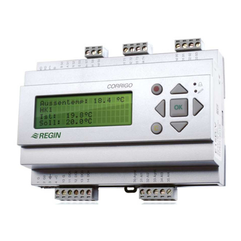
  9. Regin CORRIGO C40-LON User manual

Regin CORRIGO C40-LON User manual

2623A OKT 99 1.2.4
CORRIGO C40-LON INSTRUCTION
Corrigo C40-LON is a controller primarily intended
for controlling air handling units. It can easily be
adapted to suit different types of units.
Corrigo C40-LON has built-in capability for LON
communication. See separate LON interface manual.
Corrigo C40-LON has six 0...10 V DC control outputs,
three in sequence for controlling for example heating /
heat exchanger / cooling and two for speed control of
supply air fan and exhaust air fan and one for humidity
control. It has a number of functions and possibilities,
such as DX-cooling in one or two steps, outdoor
temperature compensation, fire damper exercise, control
and monitoring of fans and circulation pump, free
cooling, heat-exhanger efficiency calculation etc.
Corrigo C40-LON can also receive and handle a number
of alarms such as fan and filter alarm, smoke alarm,
chiller alarm, heat-exchanger alarm and has a free relay
output for total alarm. Corrigo C40-LON has a year-base
real-time clock, week-scheduler , holiday calendar,
holiday periods and automatic normal time/daylight
saving time change-over.
Installation
Mount the unit on a DIN rail in a cabinet or separate
enclosure.
For mounting in the cabinet front, use mounting kit FMC.
Degree of protection IP20
Ambient temperature 0...50°C
Wiring
Supply voltage
Terminals 42 and 43: 24 V AC, ±15%, 50/60 Hz.
Fan speed control, supply/exhaust air fans AI1, AI2
Connect AI1 and AI2 to pressure transmitters measuring
the pressure over each fan. Use transmitters with a
0...10V DC output signal. The pressure range is
adjustable.
N.B. Since these signals control vital functions they must
be connected for the unit to work as intended.
Analogue inputs AI1...AI8
N.B. All AI-inputs must refer to the signal neutral terminals
for AI-inputs (terminals 24, 27, 30, 33).
Humidity sensors AI3, AI4
AI3 and AI4 are to be connected to humidity transmitters
with output 0...10 V DC corresponding to 0...100% RH.
AI3, room humidity sensor, main sensor.
AI4, duct humidity sensor, limiting sensor placed in the
incoming air duct after the air handling unit.
Sensors AI3...AI8
Use PT1000 sensors. (See data sheet 4-150).
The choice of which sensors to connect is determined by
the choice of functions. The table, fig 3 can be used as an
aid in determining which sensors to install.
Connect the sensors according to the terminal schematics
on page 6.
AI8 is, depending on setting, used for:
1. Frost protection sensor for applications with water
heated heater.
2. High temperature limiting switch for applications with
electrical heater.
When used for high temperature limiting switch it must be
connected to a free contact closing on alarm.
!
IMPORTANT: Read these
instructions before installation
and wiring of the product.
Fig 1
Normal
Reduced
0
Auto
DI7
DI8
Fig 2
INSTRUCTION 1
ð
DMD
DTL
CorrigoCorrigo
Digital inputs DI1...DI8
The digital inputs DI1...DI8 must refer to terminal 22.
N.B. Terminal 22 must not be connected to any other
terminals but should only be used as reference for units
connected to DI1...DI8.
The inputs may only be connected to potential free
contacts.
Closed contact activates alarm or function.
Unused inputs are to be left open.
DI1 Input for filter guards
DI2 Input for circulation pump indication.
Must be connected for systems with water heating.
DI3 Input for chiller alarm
DI4 Input for rotation sentinel or ice build-up sentinel for
heat exchanger.
DI5 Input for smoke alarm.
DI6 Input for fire damper end-position indication,
external alarm or external switches ”not in Auto
position”.
(See textblock on DO6/DI6 on page 6).
DI7 Input for start of extended running time, normal flow.
DI8 Input for start of extended running time, reduced
flow.
Tel:+46 (0)31 795 44 60 Fax:+46 (0)31 795 38 50
Box 116
428 22 KÅLLERED, SWEDEN
2623A OKT 99 1.2.4
CORRIGO C40-LON INSTRUCTION
Analogue 0...10 V DC control outputs, AO1...AO6
Output signal 0...10 V DC, 5 mA. Short circuit proof.
AO1 Control output Y1
AO2 Control output Y2
AO3 Control output Y3
The function of the different outputs depends on the
configuration settings but the sequence order will always
be Y3 àY2 àY1 on increasing heat demand.
AO4 Control output, supply air fan
AO5 Control output, exhaust air fan
AO6 Humidity control
These outputs must refer to terminal 41, Signal neutral.
Since signal neutral in the Corrigo is electrically
separated from system neutral the signal neutral from
the actuator must be connected to terminal 41 even if
the actuator and the Corrigo share a common trans-
former.
Other control outputs, DO1...DO7
The digital outputs DO1...DO6 are triac controlled.
0,5A, 24 V AC. Short term peak load 1A.
Output DO7 is a potential free relay contact.
The outputs are paired to 24 V AC supply inputs. (See
terminal schematics, page 6).
For higher voltages and currents use relay modules
RM6-24/D or RM6H-24/D that are specially designed for
use with Corrigo.
Some of the outputs have alternative functions
depending on the system configuration.
DO1Activate supply air fan.
DO2Activate exhaust air fan.
DO3Control circulation pump.
DO4Control DX-chiller 1
DO5Control DX-chiller 2
DO6External frost protection or fire damper exercising.
(See text section DO6/DI6 page 6).
DO7Potential free relay contact for alarm output.
1 A, 24 V AC/DC. Closes on alarm.
Buttons and display
Language
The menu text language can be changed.
Hold the !button depressed during power up to enter the
setup mode. Then press !again and a blinking marker
will appear next to the current language. Select the desired
language by using the arrow buttons. When the marker is
next to the desired language, press OK. Press OK again
to return to the normal menu system.
All information that can be shown on the display is organi-
sed in menues in a ”menu-tree”.
Using the buttons on the front you can move between the
different menues in the tree, look at parameters, change
settings, display and reset alarms.
What you can see and do is governed by your log-on level.
The ”Trunk” of the menu-tree contains the following
menues:
Logon
Configuration Only shown in level 3
Control temp ïStarting point
Control humidity
Control pressure
Running mode
AI Analogue in
DI Digital in
AO Analogue out
DO Digital out
Scheduler
Alarm settings Not shown in level 0
Settings Only shown in level 2 and 3
During normal running when the buttons are not in use a
series of menu pages is shown.
The display alternates between, a general display with
product description and clock, setpoint/actual temperature,
and output status for the control outputs Y1, Y2, Y3.
To gain access to the menu-tree press OK and the display
will change to Control temp.
By pressing éand êyou can move up and down the tree.
The arrows to the right in the display indicate whether
there are menu pages above or below the one shown.
>Control Temp á
AI Analogue in â
To move out onto any of the ”branches” press OK. Out on
the branch you can then move about in the same way
using the arrowbuttons. By pressing Esc you can jump
back towards the trunk.
In menu pages with settable parameters you shift to
”Setting mode” by pressing !.
A dark blinking marker will then appear in the first settable
position. By using the arrow buttons the value can be
changed. When the correct value is shown press OK and
the marker will move to the next position. After OK on the
last position the new value is stored and the ”Setting
mode” is ended.
To abort without change press Esc and the marker will
move back to the previous position. Setting mode is
aborted automatically after a few minutes button-inactivity.
Shows the alarm queue. Displays active and non-
acknowleged alarms. The alarm-LED above the button is
lit when there are alarms in the queue.If there are multiple
alarms use the arrow buttons to move between pages.
Alarms are acknowleged by pressing OK.
To abort press Esc.
Login
Corrigo has 4 different login levels to prevent the user
from inadvertently changing any settings.
0Without logging in most of the important parameters
can be viewed, alarms can be acknowleged but no
parameters can be changed.
1Main setpoint, time and date can be set.
Outputs can be manually set and the running mode
can be set to manually on or off.
2Gives access to most setpoints and running para-
meters.
3Gives total access.
Used by the commissioning engineer for system
configuration.
Enables changing of login codes.
To login when the display shows the normal series of
information menues, first press OK and the display will
show Control temp.
Control Funct. á
>0 Suppl Air cnt â
INSTRUCTION 2
ð ð
*CORRIGO C40* Setpoint/Actual Y1 / Y2 / Y3
Mo 980907 10:10 20.0ºC / 20.0ºC 0% / 45% / 0%
DI7 and DI8 should, depending on settings, either be
wired to a momentarily closing pushbutton or to, for
example, a timer.
If DI7 and DI8 are both closed at the same time the unit
is shut down.
If a separate handswitch for setting the running mode is
installed it should be wired according to figure 1.
%
EF/Setp/Act/Out
275Pa/275Pa/70%
Setpoint/Actual
50%RH / 48%RH SF/Setp/Act/Out
275Pa/275Pa/70%
2623A OKT 99 1.2.4
CORRIGO C40-LON INSTRUCTION
Press éuntil the cursor arrow points at Login. Press
OK.
The login menu will be displayed.
To log in press !and a marker will be shown at the first
digit. Press éê to change the value. Press OK to
acknowlege the correct value and the marker will move
to the next digit.
If you make an error you can return to the previous digit
by pressing Esc.
After OK on the last digit the code is evaluated.
An incorrect code is rejected and an errormessage is
displayed.A correct code will display an acknowledging
message showing the login level.
After 2 seconds the system returns to the main menu.
Factory codes
On delivery the following codes are installed
Level 0 0000 Level 0 is default without having to log on
Level 1 1111
Level 2 2222
Level 3 3333
These codes can be changed when logged in at level 3.
Enter the login menu again.
Press the êuntil the menu for the level you wish to
change is shown.
Press !to enter Setting mode. A marker will be shown
at the first digit. Press éê to change the value.
Press OK to acknowlege the correct value and the
marker will move to the next digit.
If you make an error you can return to the previous digit
by pressing Esc.
After OK on the last digit the new code is acknowleged.
Save the codes in a safe place. Especially the code for
level 3.
Should the code for level 3 be lost, a one-day code can
be obtained from Regin.
Set your code
0000 Level:0
Configuration
Configuration implies the commissioning setting of all the
parameters in Corrigo.
The configuration menues are only accessible at level 3.
Choose the menu Configuration in the main menu.
Normal method (A quick method is described at the end
of the configuration section).
The configuration section comprises a number of menu
pages (A...S). Go through the pages one at a time.
In each page, choose the alternative valid for the
application on hand.
Each menu page is here described in short, showing the
available alternatives.
For detailed information, see the manual for Corrigo C40.
A. Control function
0. Constant supply air temperature
1. Constant supply air temperature with outdoor tempera-
ture compensation
2. Room temperature control with cascade control of the
supply air temperature.
3. Room temperature control with minimum/maximum
limiting of the supply air temperature.
4. Room temperature control without supply air tempera-
ture sensor.
5. Outdoor temperature controlled change-over between
constant supply air temperature control with outdoor
temperature compensation or room temperature
control.
6. Can not be used with Corrigo C40 since an exhaust air
sensor can not be connected.
B. Heater type
0. Water heated. (AI8 Frost protection sensor)
1Electric heater. (AI8 High temperature limit)
C. Output sequence Y1
0-Output not active
1AO1 Heater
2AO1 Damper
3AO1 Cooler
D. Output sequence Y2
0-Output not active
1AO2 Plate exchanger (DI4 ice-up sensor)
2AO2 Rotating exchanger (DI4 rotation sentinel)
3AO2 Liquid connected exch. (AI4 Limit sensor in
the exchanger circuit)
4AO2 Damper
Control Funct. á
>0 Suppl Air cnt â
5AO2 Heater
6AO2 Cooler
E. Output sequence Y3
0-Output not active
1AO3 Cooler
2AO3 Heater
F. Frost protection (Only if water heating is chosen).
0Not active
.Y1 Y1 forced open on frost risk.
2Y2 Y2 forced open on frost risk.
3Y1 Aut Reset.Y1 forced open, automatic reset.
4Y2 Aut Reset.Y2 forced open, automatic reset.
G. Shutdown mode (Only if water heating is chosen).
0No
1Yes
When the system is shut down Corrigo will contol the valve
actuator to maintain a preset temperature at the frost
protection sensor. Only activated at outdoor temperatures
lower than +14°C.
Needs frost protection sensor on AI8 and outdoor tempera-
ture sensor on AI5.
H. Pump stop (Only if water heating is chosen).
0No
1Yes
The water circulation pump is stopped when there is no
heating demand and the outdoor temperature is above a
preset temperature. Activation delayed 15 minutes
Stopped pump is exercised 5 minutes/day at 12:00.
Needs outdoor temperature sensor on AI5.
I. Function not available for Corrigo C40
Configuration code for this parameter must always be 0.
J. DX cooling
0No
11 stage
22 stages
33 stages binary
The outputs DO4 and DO5 are used to control DX chillers
in stages.
K. Cooling recovery
0No
1Yes
If the exhaust air is a preset number of degrees colder than
the outdoor temperature the heat exchanger or mixing
dampers will be set for maximum recovery. A heat
exchanger will be set to full capacity and dampers to
maximum recirculation.
Needs exhaust sensor on AI3 and outdoor sensor on AI5.
INSTRUCTION 3
ð
2623A OKT 99 1.2.4
CORRIGO C40-LON INSTRUCTION
Other menu branches
Control temp
In this menu branch you can look at and set most control
values for the temperature control.
See also menu branch Settings
Which of the following menues that are shown and which
values that are settable depends on the chosen control
function and which login level that has been used.
The table shows all menues and the control functions with
which they are shown.
1Setpoint/Actual temp. Control function 0, 2, 3, 4.
2Calculated setpoint Actual temp. Control function 1, 5, 6.
3Output % for Y1, Y2, Y3. Unused output shows ___.
Control function 0, 1, 2, 3, 4, 5, 6.
4Setpoint/Compensation. Control function 1, 5.
5Setpoint Room/Supply air Control function 5.
6Setpoint/Actual value. Supply air. Control function 2.
7Min-/Maximum limits. Control function 2, 3, 5, 6.
8Setpoint DX/Actual value. Room. Control function 5.
9P-band/I-time/Neutral zone. Control function 0, 1, 2, 3, 4,
5, 6.
10 Cascade factor/I-time room. Control function 2.
4
32
1
Setpoint
Outdoor temp.
CONFIG.CODE 1
0011.1110.0000 CONFIG.CODE 2
0100.010
INSTRUCTION 4
ð
11 Outdoor temp. compensation. Breakpoint 1.
Control function 1, 5.
12 Outdoor temp. compensation. Breakpoint 2.
Control function 1, 5.
13 Outdoor temp. compensation. Breakpoint 3.
Control function 1, 5.
14 Outdoor temp. compensation. Breakpoint 4.
Control function 1, 5.
The breakpoints must be placed with 1 highest and 4
lowest.
State the temperature and compensation for each point.
For temperatures higher than point 1 and lower than
point 4 the compensation is constant and equal to the
value set for respective point.
Control pressure
Parameters for pressure control of fans
1, 2 Supply Air Fan/Exhaust Air Fan. Setpoint, Actual
value and output-%. Display only.
3SAF/EAF Setpoint normal flow
4SAF/EAF Setpoint reduced flow
5, 6 SAF/EAF P-Band, I-Time, D-factor
7-10 SAF/EAF Outdoor temp compensation of flow.
Requires an outdoor sensor on AI5
ð
L. Free cooling, (Night cooling)
0No
1Yes
The function is only active during off-periods
If the room temperature exceeds a preset temperature
and the outdoor temperature is a preset value lower than
the room temperature the supply and exhaust air fans
are started to give free cooling. The outputs Y1, Y2, Y3
are all blocked.
The function is blocked at outdoor temperatures lower
than a preset value to prevent condensation problems.
Needs room sensor on AI7 and outdoor sensor on AI5.
M. Function input DI6 and output DO6
0External alarm + Frost protection
1Auto + Frost protection
2Fire damper exercise.
See text block about the function DO6/DI6, page 6.
N. Fire alarm
0Alarm only. Both fans continue to run.
1Alarm and both fans are stopped.
2Alarm and only the supply air fan is stopped.
2Alarm and only the exhaust air fan is stopped.
O. Function DI7/DI8
0Function not used.
1Pushbutton. Instantanious closure gives extended
running for preset time.
2Timer. Extended running as long as the contact is
closed.
P. Function not available to Corrigo C40
Configuration code (see below) must be set to 0
Q. Function not available for Corrigo C40
Configuration code for this parameter must always be 0.
R. Daylight saving time
0No
1Yes
Automatic change to DST at 02:00 the last Sunday in
March.
Back to normal time at 03:00 the last Sunday in October.
S. Humidity control (Output AO6)
0. Humidification via AO6 and dehumidification
(dehumidification through control of the output
AO1...AO3 which has been configured for cooling).
1. Humidification via AO6
2. Dehumidification via AO6
T. Factory settings
No / Yes. On yes all parameters will be reset to factory
values. Must be used with utmost care.Should only be
used by the commissioning engineer.
When the configuration is terminated by leaving the
configuration branch by pressing Esc an automatic
restart with the new parameters will take place. The
login level will be reset to 0.
Configuration, quick method
The top two menu pages on the configuration branch
show two configuration codes 1 and 2.
Each position in the code represents, in order, the
values set in the menues A...R described above. The
menu S ”Factory settings” is not included in the code.
The codes can be set directly in these two pages.
Code schematics
By using the supplied code schematics it is easy to
determine the code for any control application.
We recommend that you fill in the values in the line
provided and keep it in the system manual.
Control humidity
In this menu branch you can look at and set all control
values for the humidity control.
1Setpoint/Actual.
Setpoint and actual humidity for the room humidity
sensor. (Main sensor)
2Max limit/Actual.
Setpoint and actual humidity for the duct humidity
sensor. (Limiting sensor)
3P-band/I-time. Control parameters for the humidity
control.
2623A OKT 99 1.2.4
CORRIGO C40-LON INSTRUCTION
Diode Text Function yellow Function red
1SF Supply fan on SF error
2EF Exhaust fan on EF error
3Pump Pump on Pump error
4Y1 Output Y1 Over temp limit
Heating or frost protection
5Y2 Output Y2 Alarm
Exch Blinks on defrost Heat exchanger
6Y3 Cool Output Y3 Alarm chiller
7Filter --- Filter alarm
Alarm -- --- Alarm active
Running mode
In this menu the running mode for the system can be
checked and also set to manual control.
To the left the display shows Auto/Manual and to the right
the present running mode.
The modes AUTO/NORM/REDUC/OFF can be set.
In AUTO the running mode is set by the scheduler
program or by signals on DI7/DI8.
The menu is available from level 1 and up.
AI Analogue inputs
Displays current values for AI1...AI8.
The displayed sensor temperature can be adjusted
by ±2K. Available for level 3.
Maximum and minimum temperatures since last reset can
be shown. Activated in menu ”Settings”.
DI Digital inputs
Displays current values for inputs DI1...DI8.
AO Analogue outputs
Shows current values for AO1...AO5.
The outputs can be manually set. From level 1 and up.
If an output is not reset to AUTO within 15 seconds an
alarm is activated.
DO Digital outputs
Shows current values for DO1...DO7.
The outputs can be manually set. From level 1 and up.
If an output is not reset to AUTO within 15 seconds an
alarm is activated.
Scheduler
The Corrigo has a year-base clock. This means that a
week-schedule, individual holidays and holiday periods
for a full year can be set.
The clock has at least 24 hours running reserve.
1. Clock
Here weekday, date and time are set. Level 1 and up.
2. Scheduler period 1, 2, 3.
Setting of running periods. Level 2 and up.
Corrigo has 3 scheduler periods so that separate
running times can be set for, for example, weekdays,
Saturdays and Sundays/holidays. In each period, mark
the days and time interval in which the system should
be in normal running mode. Use the arrow keys to
select/deselect days in the period. End each selection
with OK.
The day H is used if the system is to have running time
during holidays or holiday periods.
3. Reduced 1, 2, 3.
3 periods for running with reduced airflow.
Should not overlap periods set for normal running.
Should periods overlap Corrigo will choose normal
running before reduced.
4. Dates for holidays. Level 2 and up.
A total of 10 individual holidays can be set. Running
time during a holiday is set by programming the day
H into one of the three scheduler periods. If none of
the periods contains the day H the system will be shut
down on holidays.
5. Holiday periods. Level 2 and up.
2 periods comprising any number of days may be
programmed. Running time during a holiday is set by
programming the day H into one of the three
scheduler periods. If none of the periods contains the
day H the system will be shut down on holidays.
Alarm settings
Here all settings for the alarm system are set.
1. Sensor alarm
Should the actual temperature differ from the setpoint
by more than the set value an alarm will be activated
after a set time.
2Outdoor temperature range within which sensor alarm
is permitted.
To prevent alarms when the outdoor temperature
leads to conditions beyond the system capacity. (For
example at temperatures higher than the setpoint in
systems without cooling).
3Alarm delay for the supply air fan.
Startup alarm supression time.
4Alarm delay for the exhaust air fan.
Startup alarm supression time.
5Blocking of the alarm output relay.
The alarm output relay can be blocked so that alarms
will only be forwarded during the set time. Outside the
set period only frost alarm, high temperature limit
alarm and fire alarm will activate the alarm relay.
Other alarms will be blocked. All alarms will however,
at all times be registered in the internal alarm list and
indicated by the red flashing alarm diod. The alarm
list menues function as normal.
6. Stop unit on alarm from rotating exchanger
A rotating heat exchanger alarm on input DI4 will stop
the whole unit.
Settings Only shown to levels 2 and 3
A number of settings that are usually only set at
commissioning.
1Setpoint frost protection system
2Setpoint Shutdown control
3Pump stop. Minimum outdoor temp and delay time
4Supply fan run on time for cooling electric heater
5100% on startup
6Extension of running time when using pushbutton
7P-band for Y2, Y3. Factor of P-band for Y1
8Min fresh air when using mixing damper on Y2
9Free cooling. Min outdoor temp and min temperature
difference indoor/outdoor
10 Free cooling. Room temperature setpoint.
11 Cooling recovery. Differential outdoor/return temp
12 DX cooling. Minimum on and off times
13 Lowered minimum limit by DX cooling
14 DX cooling. Lowest outdoor temp
15 Time for fire damper exercise
16 Force low speed on fans at low outdoor temperature
17 Pressure range for transmitters for SF and EF
18 Damping factor for pressure signals SF and EF
19 Show Min/Max values for AI3...AI8
LEDs
The LEDs are connected to the functions of certain in-
and outputs. Normal running indication is yellow. A red
LED signifies an error. The text strip can easily be
changed to reflect various configurations
INSTRUCTION 5
ð
This in order to prevent uneconomic running and
running at too low a temperature.
Is only displayed if rotating exchanger has been
configured.
ð
2623A OKT 99 1.2.4
CORRIGO C40-LON INSTRUCTION
Damper 1
0° 90° DI6
Terminal 22
Damper 2
Damper 3
Damper ..
DO6
DI6
High
High
Low
Low
max 3
minutes max 3
minutes
DO6/DI6
The output/input pair DO6/DI6 can be configured for
different functions.
When Corrigo is used with relay unit RM6H-24/D or if
external switches for manual fan control are used, fire
damper exercising cannot be done through the Corrigo.
DO6/DI6 are then used for other purposes
0. Frost alarm / External alarm
DO6 is used to stop the fans in the event of frost risk.
DO6 is normally closed but will open on a frost alarm on
AI8. DI6 is used as input for external alarm signals.
1. Frost alarm / Auto position
DO6 is used to stop the fans in the event of frost risk.
DO6 is normally closed but will open on a frost alarm on
AI8. DI6 is used to activate an alarm if any of the manual
switches on RM6H-24/D is left in other position than
”Auto” for longer than 15 seconds.
2. Fire damper exercising
Wire all the damper end-position switches to DI6
according to the figure above. The contacts must close
when the actuator is at either end position.
At a preset time DO6 will activate all the dampers. DI6
must then be deactivated within 3 minutes, indicating
thet the dampers have left their normal end position , or
an alarm will be activated. When DI6 has been
deactivated it must be activated again within 3 minutes
indicating that the dampers have reached the other end
point. When DI6 is activated the output DO6 is
deactivated and the dampers begin to return to the start
position. To avoid an alarm output DI6 must once again
be deactivated within 3 minutes and then activated
again within 3 minutes indicating that the dampers are
back in their original position.
Factory settings
Configuration Factory settings
Config.code 1 0011.1110.0000
Config.code 2 0100.010
A. CONTROL FUNCTION 0 Supply air temp control
B. HEATER TYPE 0 Water heater
C. SEQUENCE Y1 1 Heating
D. SEQUENCE Y2 1 Plate exchanger
E. SEQUENCE Y3 1 Cooling
F. FROST PROTECTION 1 Y1
G. SHUTDOWN CONTROL 1 Yes
H. PUMP STOP 0 No
I. FUNCTION NOT AVAILABLE 0 No
J. DX-COOLING 0 No
K. COOLING RECOVERY 0 No
L. FREE COOLING 0 No
M. FUNCT. DI6/DO6 0 Ext. alarm+frost prot.
N. FIRE ALARM 1 SAF + EAF Stop
O. FUNCTION DI7/8 0 ---
P. FUNCTION NOT AVAILABLE 0
Q. FUNCTION NOT AVAILABLE 0
R. DAYLIGHT SAVING TIME 1 Yes
S. HUMIDITY CONTROL 0 Humidif./Dehumidif.
T. FACTORY SETTING No
Control Temp
Setpoint 20.0°C
P-Band / I-time / Neutral zone 20K / 60s / 2K
Control Humidity
Setpoint / Actual ---
Max limit / Actual 80%RH
P-Band / I-time 40%RH / 60s
Control Pressure
Setpoint 300Pa
P-Band / I-time / D-factor 200Pa / 60s /0
INSTRUCTION 6
Storage of programmed parameters
All settings are stored in non-volatile memory so the unit
does not need reprogramming after a long power
failiure.
The clock has a power reserve of at least 24 hours.
After longer power failiures the clock will need resetting
but not the programmed scheduler parameters.
The alarm list will be erased at a power failiure.
EMC emissions & immunity standards:
This product conforms with the requirements of Euro-
pean EMC standards CENELEC EN 50081-1 and EN
50082-1 and carries the CE mark.
CONFIGURATION- Corrigo C40-LON A B C D .EFGH. I JKL
Configuration code 1 . . 0
A Control function
0. Supply air control 0
1. Supply air control with outdoor temperature compensation 1
2. Room control with cascaded supply air temperature control 2
3. Room control with min/max limiting of supply air temp. 3
4. Room control, single sensor 4
5. Supply air control/Room control. Outdoor temp dependent 5
6. Not available for Corrigo C40 -
B Heater type
0. Water heater 0
1. Electric heater 1
C Output Y1
0. Not active 0
1. Heating 1
2. Damper 2
3. Cooling 3
D Output Y2
0. Not active 0
1. Plate heat exchanger 1
2. Rotating heat exchanger 2
3. Not available for Corrigo C40 -
4. Damper 4
5. Heating 5
6. Cooling 6
E Output Y3
0. Not active 0
1. Cooling 1
2. Heating 2
F Frost protection (Water heating only)
0. Not active 0
1. Active on Y1 1
2. Active on Y2 2
3. Active on Y1 with automatic alarm reset 3
4. Active on Y2 with automatic alarm reset 4
G Shutdown mode (Water heating only. Requires outdoor sensor)
0. No 0
1. Yes 1
H Pump stop (Water heating only. Requires outdoor sensor)
0. No 0
1. Yes 1
I Function not available for Corrigo C40
This code must always be set to 0 0
J DX-cooling
0. No 0
1. 1-step 1
2. 2-step 2
3. 3-step binary 3
K Cooling recovery
0. No 0
1. Yes 1
L Free cooling
0. No 0
1. Yes 1
CONFIGURATION- Corrigo C40-LON MNOP. Q RS
Configuration code 2 0.0
M Function DI6/DO6
0. External alarm & frost protection 0
1. Auto position & frost protection 1
2. Fire damper exercising
N Fire alarm
0. Alarm only 0
1. Alarm + supply air and exhaust air fans stop 1
2. Alarm + supply air fan stops 2
3. Alarm + exhaust air fan stops 3
O Function DI7/DI8
0. Not active 0
1. Pushbutton 1
2. Timer 2
P Function not available for Corrigo C40
This code must always be set to 0 0
Q Function not available for Corrigo C40
This code must always be set to 0 0
R Daylight saving time
0. No 0
1. Yes 1
S Humidity control
0. Humidification / Dehumidification 0
1. Humidification 1
2. Dehumidification 2

Other Regin Controllers manuals

Regin AQUA230T User manual

Regin

Regin AQUA230T User manual

Regin Corrigo E User manual

Regin

Regin Corrigo E User manual

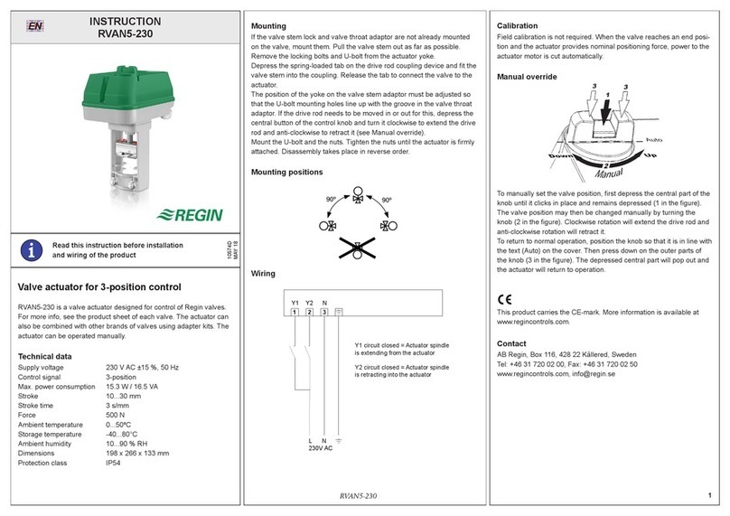
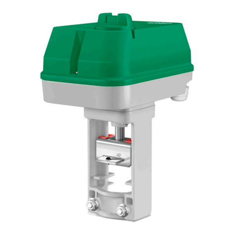
Regin RVAN5-24A User manual

Regin

Regin RVAN5-24A User manual

Regin TTC25X User manual

Regin

Regin TTC25X User manual

Regin Corrigo User manual

Regin

Regin Corrigo User manual

Regin RDAS18S-24C User manual

Regin

Regin RDAS18S-24C User manual

Regin CORRIGO L10 User manual

Regin

Regin CORRIGO L10 User manual

Regin TTC 2000 User manual

Regin

Regin TTC 2000 User manual

Regin RVAR5-24A User manual

Regin

Regin RVAR5-24A User manual

Regin TTC25X User manual

Regin

Regin TTC25X User manual

Regin Exigo User manual

Regin

Regin Exigo User manual

Regin TTC80F User manual

Regin

Regin TTC80F User manual

Regin RVAZ4L1-230 User manual

Regin

Regin RVAZ4L1-230 User manual

Regin PCMTV50-F20 User manual

Regin

Regin PCMTV50-F20 User manual

Regin REGIO RC-T User manual

Regin

Regin REGIO RC-T User manual

Regin RVAR10-230 User manual

Regin

Regin RVAR10-230 User manual

Regin REGIO MINI RC-DO User manual

Regin

Regin REGIO MINI RC-DO User manual

Regin RVAN25-24 User manual

Regin

Regin RVAN25-24 User manual

Regin RVAZ4-230 User manual

Regin

Regin RVAZ4-230 User manual

Regin REGIO RC-F User manual

Regin

Regin REGIO RC-F User manual

Regin Regio Midi User manual

Regin

Regin Regio Midi User manual

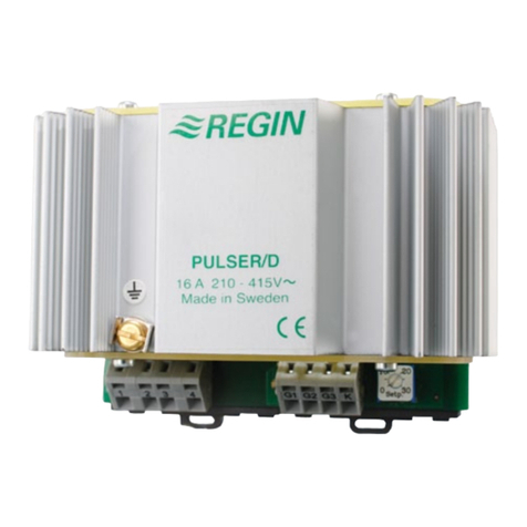
Regin PULSER/D User manual

Regin

Regin PULSER/D User manual

Regin RDAS7S-24C User manual

Regin

Regin RDAS7S-24C User manual

Regin TTC63F User manual

Regin

Regin TTC63F User manual

Popular Controllers manuals by other brands

DIEGON AP80 manual

DIEGON

DIEGON AP80 manual

KING UC1000 user manual

KING

KING UC1000 user manual

VARIZOOM VZ-ROCK operating instructions

VARIZOOM

VARIZOOM VZ-ROCK operating instructions

KONTRONIK JIVE Pro 80+ HV Operation manuals

KONTRONIK

KONTRONIK JIVE Pro 80+ HV Operation manuals

JETI model Max BEC 2D manual

JETI model

JETI model Max BEC 2D manual

LAE BR1-28 Instructions for use

LAE

LAE BR1-28 Instructions for use

Mitsubishi Electric QD77MS user manual

Mitsubishi Electric

Mitsubishi Electric QD77MS user manual

Continental Instruments CICP1100 datasheet

Continental Instruments

Continental Instruments CICP1100 datasheet

HP Surestore Disk Array 12h - And FC60 installation guide

HP

HP Surestore Disk Array 12h - And FC60 installation guide

YASKAWA motoman NX100 manual

YASKAWA

YASKAWA motoman NX100 manual

IOtech Personal488 user manual

IOtech

IOtech Personal488 user manual

SMC Networks ITV1050 Installation and maintenance manual

SMC Networks

SMC Networks ITV1050 Installation and maintenance manual

Lexicon DC-1 Quick reference guide

Lexicon

Lexicon DC-1 Quick reference guide

Rohm BD93F10MWV Application note

Rohm

Rohm BD93F10MWV Application note

Novusun CNC NCB01 manual

Novusun CNC

Novusun CNC NCB01 manual

Merobel DGT300+ instruction manual

Merobel

Merobel DGT300+ instruction manual

Burkert 787 649 operating instructions

Burkert

Burkert 787 649 operating instructions

ABB 8130.6 user manual

ABB

ABB 8130.6 user manual

manuals.online logo
manuals.online logoBrands
  • About & Mission
  • Contact us
  • Privacy Policy
  • Terms and Conditions

Copyright 2025 Manuals.Online. All Rights Reserved.