Elma Cyclomotion User manual

Elma Schmidbauer GmbH Gottlieb-Daimler-Str. 17 D-78224 Singen Phone +49 (0)7731 / 882-0 Fax +49 (0)7731 / 882-266 [email protected]om
www.elma-ultrasonic.com
document ref. 104 6474
Operating Instructions
Fig. Cyclomotion pro
Cyclomotion
Watchwinder
english

2
BA_Cyclomotion_EN_Vers.09.2019
© Elma Schmidbauer GmbH
Contents
1General....................................................................... 3
2Safety warnings.......................................................... 3
2.1 Instructions for the use of the present manual.......... 3
2.2 Instructions for the use of the unit............................ 4
3Product description..................................................... 5
3.1 Cyclomotion product features .................................. 5
3.2 CE conformity.......................................................... 5
3.3 Delivered equipment................................................ 6
3.4 Optional accessories................................................ 6
3.5 Technical details...................................................... 7
3.6 Functioning of the Cyclomotion................................ 8
3.7 Front view................................................................ 9
3.8 Rear view................................................................10
3.9 Operating panel......................................................11
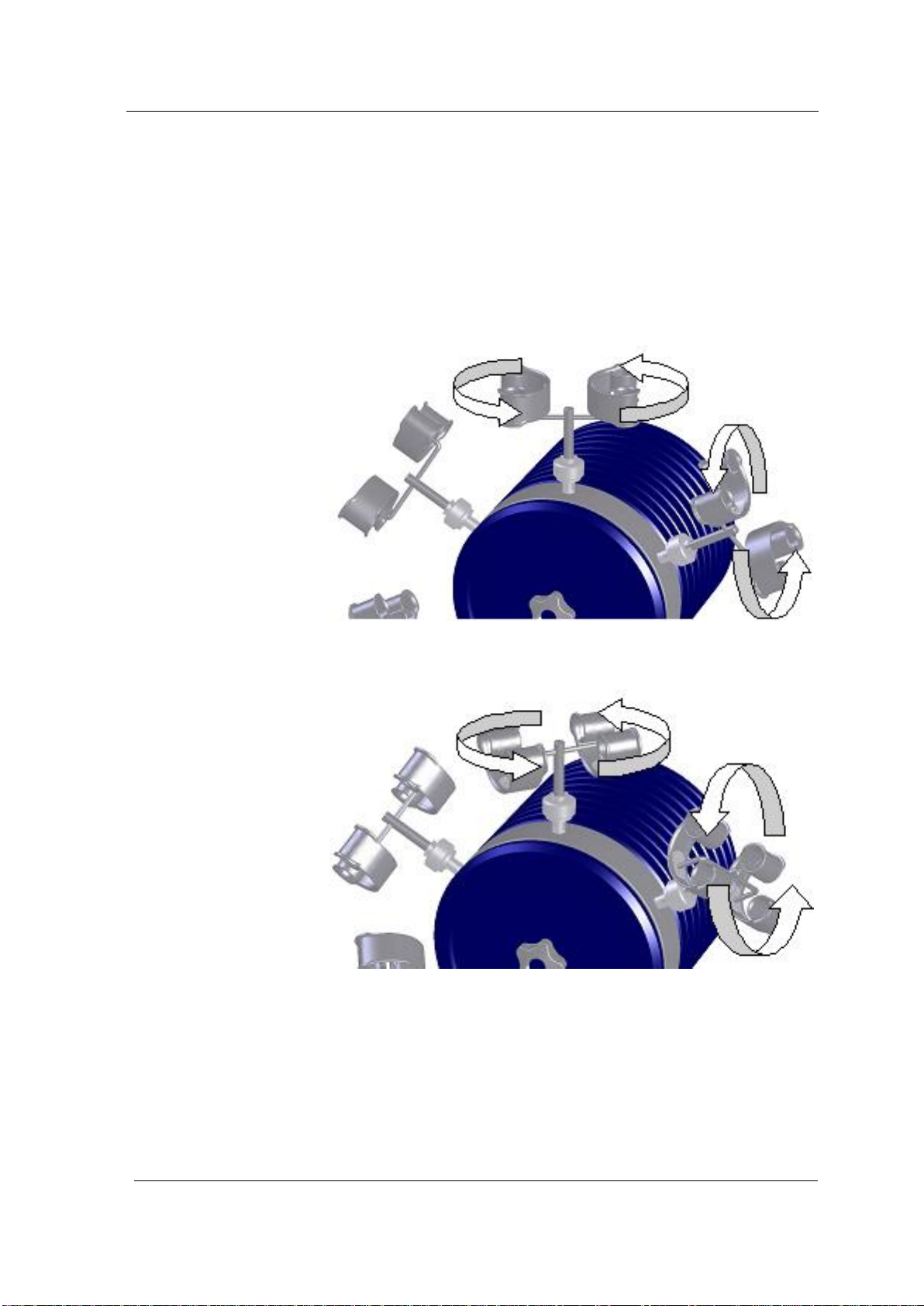
3.10 Individual combination of clips ................................11
3.10.1 Description of the clips .....................................12
3.10.2 Combination examples.....................................13
4Before initial operation.............................................. 14
4.1 Unpacking and placement.......................................14
4.2 Connection to the mains .........................................14
5Initial operation......................................................... 15
6Setting of the wind-up mode..................................... 17
7Maintenance............................................................. 18
7.1 Maintenance of the unit...........................................18
7.2 Cleaning of the protecting hood (Optional)* ............19
8Putting out of action and waste disposal .................. 21
9Manufacturer’s contact address ............................... 21

General
© Elma Schmidbauer GmbH
BA_Cyclomotion_EN_Vers.09.2019
3
1 General
The present Operating Instructions are part of the delivered
equipment. They must be ready for use at any time and remain
with the unit in case of resale.
We reserve the right to carry out technical modifications on the
unit due to advanced development.
An operating manual cannot take account of every conceivable
use. An operating manual cannot take account of every
possible use. Contact your dealer or the manufacturer for
further information or in the event of problems which are not
covered or not sufficiently covered in this operating manual.
2 Safety warnings
Please observe any additional national safety regulations that
may apply.
The manufacturer cannot be held liable for damages on
persons, equipment or watches caused by improper use.
The operator is responsible for the instruction of the operating
staff.
2.1 Instructions for the use of the present manual
Symbols used in the present manual
This symbol warns of the risk of injury caused by electricity.
This symbol warns of the risk of slight injury and damage to the
equipment.
This symbol marks additional information.
Exclusion of liability

Safety warnings
4
BA_Cyclomotion_EN_Vers.09.2019
© Elma Schmidbauer GmbH
2.2 Instructions for the use of the unit
The present Cyclomotion or Cyclomotion pro unit has been
designed for the winding up of mechanic (automatic) watches
only.
Operation of the unit by authorized and instructed staff only.
Observe the instructions given in the present manual.
Check the Cyclomotion and the power supply unit for transport
damages. In case of visible damage do not operate the unit!
In order to move the Cyclomotion to another place hold the unit
by the handle on the rear and the foot. Do not lift and carry the
Cyclomotion by the acrylic glass hood.
Place the unit on a dry and solid surface. Ensure that the
workplace is sufficiently ventilated and keep workplace and unit
dry.
Allowed ambient temperature: +5° to +30°.
For safety reasons, the present unit must be connected to a
correctly grounded socket only. The technical details indicated
on the nameplate must correspond with the available mains
connection details, in particular those of the mains voltage and
current connected value.
If the Cyclomotion and/or the mains cable are damaged do not
connect the unit to the mains!
The unit must be opened by authorised and specialised staff
only.
For cleaning the acrylic glass hood (Cyclomotion pro) use
cleaning media that are suitable for acrylic glass surfaces and
ensure that the acrylic glass hood cannot be scratched.
Intended use
User
Check for transport
damages
Transportation
Placement
Mains connection
Prevention of
electrical accidents

Product description
© Elma Schmidbauer GmbH
BA_Cyclomotion_EN_Vers.09.2019
5
3 Product description
Watch winder, the „artificial wrist“ for checking and winding up
automatic watches. The watch is put into any position possible
when worn on the wrist.
3.1 Cyclomotion product features
The standard unit is delivered without clips. For operating
the unit, 6 clips must be ordered separately; 5 different
types of clip are available.
The Cyclomotion is available in 2 versions; individual
adjustment of the bows is possible.
Change of rotational direction is possible; also suitable
for large and heavy watches (up to 200 g).
Individual combination(s) of clips possible; this allows the
simultaneous winding up of watches that are wound up in
both directions and of watches that are wound up in one
direction only.
2 different speeds available (1 or 4 rpm) for permanent
winding up and for quick winding up
Powerful, silent motor with integrated safety clutch and
holding torque (in standby mode) for the perfect
protection of the watches.
Optional: lockable protecting hood protects the watches
from dust and mechanical damage (Cyclomotion pro
only).
Manual, mechanical interruption of the service
programme possible.
3.2 CE conformity
The present Elma unit is in compliance with the CE marking
criteria with reference to
the EMC Directive 2004 / 108 / EWG (EEC)
the Machinery Directive 2006 / 42 / EWG (EEC)
The declaration of conformity is available from the
manufacturer.

Product description
6
BA_Cyclomotion_EN_Vers.09.2019
© Elma Schmidbauer GmbH
3.3 Delivered equipment
Basic unit Cyclomotion or Cyclomotion pro
Power supply unit
Operating Instructions
3.4 Optional accessories
„Watch clip 2“ 165 –205 mm 103 5190
„Watch clip 4“ 165 –205 mm 103 5192
„Watch clip 2 left / right“165 –205 mm 103 5359
„Watch clip 4 left / right“ 165 –205 mm 103 5360
„Watch clip 2“ 150 – 165 mm 104 5571
„Watch clip 4“ 150 – 165 mm 104 5573
„Watch clip 2 left / right“ 150 –165 mm 104 5566
„Watch clip 4 left / right“ 150 –165 mm 104 5568
“Watch box” for up to 4 watches 105 3528
„Industrial clip 4“ 103 5361
„Wall mounting device“ for Cyclomotion 103 5701

Product description
© Elma Schmidbauer GmbH
BA_Cyclomotion_EN_Vers.09.2019
7
3.5 Technical details
Mains voltage (Vac)
100 - 240
Mains frequency (Hz)
50 / 60
Sense of rotation
left / right
Revolutions radial (rpm)
1 or 4
Revolutions axial (rpm)
4.5 or 18
Clip
6 (12 or 24 watches)
Cyclomotion max. W / D / H (mm)
465 / 325 / 520
Cyclomotion pro max. W / D / H (mm)
635 / 325 / 585
Weight Cyclomotion (kg)
approx. 11
Weight Cyclomotion pro (kg)
approx. 16
Weight of clip (kg /pce)
approx. 0.1
Load per clip (g)
max. 200
Material housing
aluminium, coated
Material protecting hood (Cyclomotion pro)
acrylic glass
Power consumption total (W)
approx. 24
Power consumption standby mode (W)
approx. 24

Product description
8
BA_Cyclomotion_EN_Vers.09.2019
© Elma Schmidbauer GmbH
3.6 Functioning of the Cyclomotion
The speed of the spindle head (fig. 3.7. G) can be set to either
1 or 4 revolutions per minute (rpm). Due to the internal speed
increase the rotating speed of the clip is 4.5 times higher. The
watches are wound up either in both rotational directions or in
only one rotational direction depending on the type of watch
(see figures 3.6.1. and 3.6.2.).
Fig. 3.6.1. Clip for watches that are wound up in either direction
Fig. 3.6.2. Clip for watches that are wound up in one particular
direction only
Sense of rotation left: only left winding
Sense of rotation right: only right winding
Movement

Product description
© Elma Schmidbauer GmbH
BA_Cyclomotion_EN_Vers.09.2019
9
3.7 Front view
Fig. 3.7. front view
Operating panel (detailed view see below)
Mechanic disengaging screw
Protecting hood (Cyclomotion pro only)
Knurled screw for fastening the clips
Lock on protecting hood (Cyclomotion pro only)
Clip
Spindle head
A
B
C
D
E
F
G
A
B
C
D
G
E
F

Product description
10
BA_Cyclomotion_EN_Vers.09.2019
© Elma Schmidbauer GmbH
3.8 Rear view
Fig. 3.8. Rear view
Main switch
DC socket / connection for power supply unit
Handle
A
B
C
C
B
A

Product description
© Elma Schmidbauer GmbH
BA_Cyclomotion_EN_Vers.09.2019
11
3.9 Operating panel
Fig. 3.9. Operating panel
ON/OFF button
Button for setting the sense of rotation
Button for setting the speed
Start/Stop button (special operation mode, see Section 6:
Setting of the wind-up mode)
3.10 Individual combination of clips
The Cyclomotion (pro) can be equipped with 6 clips. You can
choose individual clip combinations to adjust the Cyclomotion to
your personal needs. You can combine clips for various winding
up modes (winding up in one or both directions) with clips for 2
or 4 watches or with industrial clips or with watch boxes.
Please observe the following description of the available clips
(see section 3.10.1) and of the combination examples (see
section 3.10.2).
A
B
C
D
B
A
C
D

Product description
12
BA_Cyclomotion_EN_Vers.09.2019
© Elma Schmidbauer GmbH
3.10.1 Description of the clips
Watch clip 2
for winding in both directions; for 2
watches with straps
Watch clip 4
for winding in both directions; for 4
watches with straps
Watch clip 2 left/right
for winding in one direction (left or
right depending on the watch); for
2 watches with straps
Watch clip 4 left/right
for winding in one direction (left or
right depending on the watch); for
4 watches with straps
Watch box
for up to 4 watches without straps,
max. Ø 43 mm
Industrial clip 4
for winding in both directions; for 4
watches without straps

Product description
© Elma Schmidbauer GmbH
BA_Cyclomotion_EN_Vers.09.2019
13
3.10.2 Combination examples
You want to wind up 12 watches with straps; the watches are
wound in both directions. In this case you can mount e.g. 6x
„watch clip 2“.
You want to wind up 24 watches with straps; the watches are
wound in one particular direction. In this case you can mont e.g.
6x „watch clip 4 left/right“.
You want to wind up 18 watches: 14 watches are with straps, 4
watches are without straps. 10 of the 14 watches are wound in
both directions, 4 watches are wound in right direction only.
Equip your Cyclomotion with the „Elma Watch box“for the 4
watches without straps; with one „watch clip 2“ and 2x with
„watch clip 4“ for the 10 watches that are wound in both
directions; and 2x with „watch clip 2 left/right“ for the 4 watches
that are wound in right direction only. Set the sense of rotation
to “right” (see section 6).
You want to wind up 12 watches: 9 watches are with straps, 3
watches are without straps. 3 of the 9 watches are wound in
both directions; 3 watches are wound in right direction only; 3
watches are wound in left direction only. Equip your
Cyclomotion with the “Elma Watch box” for the 3 watches
without straps; 2x with “watch clip 2” for the 3 watches that are
wound in both directions; and with 3x “watch clip left/right” for
the remaining 6 watches that are wound in one direction only.
Activate the automatic change of the sense of rotation (see
section 6) to ensure that all watches are wound up.
You can wind up watches that are wound in both directions and
watches that are wound in one direction only at the same time.
Ensure that you set the correct sense of rotation on your
Cyclomotion (see also section 6).
You would like to wind watch movements on the Cyclomotion.
Clamp this
in a plastic calotte in the "industry clamp 4”
Example 1
Example 2
Example 3
Example 4
Example 5

Before initial operation
14
BA_Cyclomotion_EN_Vers.09.2019
© Elma Schmidbauer GmbH
4 Before initial operation
4.1 Unpacking and placement
Please keep the original packing for possible service purposes,
or dispose of it according to the relevant waste disposal
regulations. You can also return the packing to the
manufacturer or your supplier (charges to your account).
Check the unit for possible transport damages before initial
operation. In case of visible damage do not put the unit into
operation. Contact your supplier and forwarding agent.
For operation place the unit on a dry, solid and level surface.
The watch clips are secured for transportation purposes by
means of one cable strap each. Remove the cable straps
before you operate the unit.
Allowed ambient temperature during operation:
+5°C to +30°C.
4.2 Connection to the mains
Check the technical data indicated on the nameplate of the
Cyclomotion and ensure that they correspond with the available
mains connection conditions, in particular the mains voltage.
Plug the delivered power supply unit into an earthed socket and
connect the cable to the DC socket on the unit rear
(see fig. 3.8.B).
Packing
Check for transport
damages
Placement
Remove transport
safety device
Ambient conditions
Before connection to
the mains

Initial operation
© Elma Schmidbauer GmbH
BA_Cyclomotion_EN_Vers.09.2019
15
5 Initial operation
1. Fix the watches or the clockworks to the clips. The elastic
coating on the clips protects the watch cases against
scratches.
2. To mount a clip with fixed watches or clockworks to the
spindle head, turn the spindle head so that the empty clip
support is at the top. There are two ways to do this:
Put the main switch on the unit rear (see fig.3.8.A) in
position Ito switch it on and press the on/off key (fig.
3.9.A). Press the start/stop key (fig. 3.9.D) to start the
Cyclomotion, let the spindle head move into the required
position and press the start/stop key again to stop the
Cyclomotion.
Or turn the disengaging screw (fig. 3.7.B) to the left to
separate the spindle head from the drive shaft. Now turn the
spindle head into the required position by hand and
retighten the disengaging screw.
Note: The spindle head can be turned by hand even with
tightened disengaging screw. In this case, you need more
force to move the spindle head against the resistance. The
drive mechanism will not be damaged.
3. Mount the clips with fixed watches or clockworks to the
spindle head one after the other. For this, open the knurled
screw of the empty clip support (see fig. 3.7.D), insert a clip
and retighten the knurled screw. Then move the next clip
support in the required position and mount the second clip,
etc.
If the knurled screws are not retightened sufficiently the
clips may slip out of the supports during operation causing
damage to the watches or clockworks.
Note! Ensure that the weight of the watches is distributed
evenly over the complete circumference of the spindle head.
Cyclomotion pro: If you need to wind up very large watches
with a diameter > 50 mm check if there is enough space
between the watch(es) and the acrylic glass hood and the lock
(on the Cyclomotion the foot) to prevent scratch damages on
the watch(es) and or the unit. We recommend to fix large
watches to the bottom position of the watch clip 4 or to a watch
clip 2.
The manufacturer cannot be held liable for any damage caused
on/by watches with a diameter > 50 mm.
Fix the
watches/clockworks
to the clips

Initial operation
16
BA_Cyclomotion_EN_Vers.09.2019
© Elma Schmidbauer GmbH
4. Put the main switch on the unit rear (see fig. 3.8.A) in
position Ito switch it on.
The Cyclomotion is now in standby mode. The ON/OFF
button is lighted red.
5. For a complete switch-off put the main switch into position 0.
When the unit is switched off by the main switch, it is separated
from the mains and does not consume any electricity.
Due to their own weight watches fixed to the clips may cause
the spindle head to move into a final position after switch-off.
How to switch the
unit on or off

Setting of the wind-up mode
© Elma Schmidbauer GmbH
BA_Cyclomotion_EN_Vers.09.2019
17
6 Setting of the wind-up mode
The unit is correctly connected to the mains as described in
Section 4.2.; the main switch (see fig. 3.8.A) is switched on
(standby mode). The on/off button (fig. 3.9.A) is lighted red.
Switch on the unit at the ON/OFF button (fig. 3.9.A) to activate
the operating panel.
The on/off button is now lighted green.
Press the start/stop button (fig. 3.9.D). Now, the on/off button is
lighted green (fig. 3.9.A). The unit starts the winding process.
To stop the winding process press the start/stop button again.
The green light in the button turns dark.
You can select 2 different speeds of rotation:
4 rpm: Press the top button for setting the speed of rotation
(fig. 3.9.C). 4 rpm is the pre-set speed on the delivered unit.
1 rpm: Press the bottom button for setting the speed of rotation
(fig. 3.9.C).
The speed of rotation can be changed during operation. The
final setting is saved when the unit is switched off.
There are 2 options to set the sense of rotation:
Right-hand rotation:Press the top button for setting the sense
of rotation (fig. 3.9.B). Right-hand rotation is pre-set on the
delivered unit.
Left-hand rotation: Press the bottom button for setting the
sense of rotation (fig. 3.9.B).
The sense of rotation can be changed during operation. The
final setting is saved when the unit is switched off.
Keep the start/stop button pressed for 2 sec to activate the
automatic change of sense of rotation: the unit starts rotating in
the sense that had been activated last (right-hand rotation on a
new unit); the sense of rotation changes regularly every 30 min.
The button light flashes.
Both speed and sense of rotation can be changed by hand
while the automatic change of sense of rotation is activated.
The 30 min change cycle continues.
Activate the
operating panel
Start winding
process
Stop the winding
process
Set the speed of
rotation
Set the sense of
rotation
Automatic change of
sense of rotation

Maintenance
18
BA_Cyclomotion_EN_Vers.09.2019
© Elma Schmidbauer GmbH
7 Maintenance
7.1 Maintenance of the unit
Pull the mains plug before you carry out any maintenance
and care works!
For reasons of safety check mains cable, power supply unit and
power input socket on the unit for damage in regular intervals.
Use original accessories only.
In case of a technical fault please contact your supplier or the
manufacturer of the unit.
For repair or spare parts orders please quote the serial number
of the unit.
Repair and maintenance works that require the unit to be
opened and connected to the mains must be carried out by
authorised and specialised staff only.
Always separate the unit from the mains before you open it.
The manufacturer cannot be held liable for any damage caused
by unauthorised repair.
In case of damage contact your supplier or the manufacturer of
the unit.
Mains cable and
mains connection
Repair
Opening of the unit
by authorised
specialised staff only

Maintenance
© Elma Schmidbauer GmbH
BA_Cyclomotion_EN_Vers.09.2019
19
7.2 Cleaning of the protecting hood (Optional)*
* Cyclomotion pro only
Fig. 7.2.1 Cyclomotion pro with open protecting hood
Mechanic disengagement screw with shaft
Front plate
Spindle head
To facilitate cleaning and care of the protecting hood inside,
remove the spindle head with the mounted watch clips.
1. Remove all watch clips.
2. Loosen the disengagement screw (fig. 7.2.1.A).
3. Pull the shaft with the disengagement screw to the front as
far as it will go (fig. 7.2.1.A).
4. Remove the front plate together with the disc springs
(fig. 7.2.1.B).
5. Carefully take out the complete spindle head with the
mounted watch clips (fig. 7.2.1.C).
6. Now there is more room to clean the acrylic glass of the
protecting hood on the inside. Use cleaning media and
wiping cloths that are compatible with the material to protect
the acrylic glass surfaces against scratching.
A
B
C
Cleaning and care
B
A
C

Maintenance
20
BA_Cyclomotion_EN_Vers.09.2019
© Elma Schmidbauer GmbH
7. Mount the spindle head. Follow the above steps in reverse
order and ensure that all components are correctly
assembled, in particular the disc springs.
Fig. 7.2.2. Position of the disc springs
Disc springs
This manual suits for next models
1
Table of contents