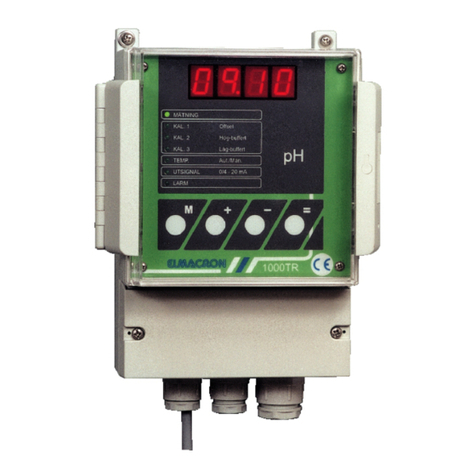
ELMACRON 1005RE User manual

1005RE
ORP% v1.1b
Instructions

\\Elmacron-server\Gemensam\Instruktioner\Instruktioner i Word\1005RE\Engelska\1005RE-ORP%E.doc
- 1 -
- Senast utskrivet 2007-10-11
11:16
TABLE OF CONTENTS
1. INTRODUCTION.............................................................................................................................................2
1.1 COMMON INTRODUCTION......................................................................................................................2
1.2 PARTS & ACCESSORY..............................................................................................................................2
2. INSTALLATION ..............................................................................................................................................3
2.1 CASING........................................................................................................................................................3
2.2 MOUNTING.................................................................................................................................................3
2.3 CONNECTIONS...........................................................................................................................................3
2.3.1 Preparation ............................................................................................................................................3
2.3.2 Connection of the power supply .............................................................................................................4
2.3.3 Connection of dosing pumps and valves ( control outputs )...................................................................4
2.3.4 Connection to an external alarm............................................................................................................4
2.3.5 Connection of the electrode....................................................................................................................4
2.3.6 Connection of a recorder........................................................................................................................4
2.4 CHECK THE CONNECTIONS....................................................................................................................4
2.5 EXAMPLE OF INSTALLATION AT ON/OFF AND PWM REGULATION ............................................5
2.6 EXAMPLE OF INSTALLATION AT FREQUENCY REGULATION.......................................................5
3. FUNCTIONS .....................................................................................................................................................6
3.1 COMMON FUNCTIONS .............................................................................................................................6
3.2........................................................................................................................................................................6
3.2.1 MEASURE..............................................................................................................................................6
3.2.2 CAL. 1.....................................................................................................................................................6
3.2.3 EXIT TO MEASURE...............................................................................................................................6
3.2.4 L1............................................................................................................................................................6
3.2.5 L2............................................................................................................................................................6
3.2.6 X1 ...........................................................................................................................................................6
3.2.7 X2 ...........................................................................................................................................................6
3.2.8 PWM.......................................................................................................................................................6
3.2.9 FRK ........................................................................................................................................................7
3.2.10 P-BAND................................................................................................................................................7
3.2.11 I-TIME..................................................................................................................................................7
3.2.12 ALARM.................................................................................................................................................7
3.2.13 OUTPUT ..............................................................................................................................................7
3.3 KEY FUNCTIONS .......................................................................................................................................8
4. REGULATION..................................................................................................................................................9
4.1 ON/OFF REGULATION..............................................................................................................................9
4.2 FREQUENCY REGULATION ....................................................................................................................9
4.3 PWM ( PULSE WIDTH MODULATED ) REGULATION .................................................................................10
4.4 I-TIME.........................................................................................................................................................11
5. SETTINGS.......................................................................................................................................................12
5.1 DEFAULT SETTINGS...............................................................................................................................12
5.2 PARAMETER SETTINGS.........................................................................................................................12
5.2.1 Relay configuration..............................................................................................................................12
5.2.3 Output signal........................................................................................................................................14
5.3 CALIBRATION..........................................................................................................................................15
5.4 OPERATION ..............................................................................................................................................15
5.5 ALARM.......................................................................................................................................................15
6. MAINTENANCE ............................................................................................................................................16
6.1 HARDWARE CHECK ...............................................................................................................................16
6.2 PRE-CALIBRATION .................................................................................................................................16
6.3 RESET OF DEFAULT SETTINGS............................................................................................................17
7. TROUBLE SHOOTING.................................................................................................................................17
8. SPECIFICATIONS.........................................................................................................................................18

\\Elmacron-server\Gemensam\Instruktioner\Instruktioner i Word\1005RE\Engelska\1005RE-ORP%E.doc
- 2 -
- Senast utskrivet 2007-10-11
11:16
1. INTRODUCTION
1.1 COMMON INTRODUCTION
1005RE is a new CE-approved series of controllers from Elmacron AB. In the series, there are
instruments for pH, Redox% and Redox mV measurement/ control.
1005RE is easy to program, calibrate and use.
The layout is clear; a large display with four LED-segments, diode indication for the menu and four
large function keys. All parameters are entered/changed with the function keys.
When connecting an electrode to 1005RE-ORP% the display shows the actual measured value in the
solution measured.
1005RE-ORP% is provided with an isolated output 0/4 - 20 mA, proportional to the measured value,
for connection to, for example, a computer, printer or other recording equipment. When measuring is
interrupted, the output stays frozen at the latest measured value.
1005RE has four relay outputs which can be set high/high, low/low, high/low and low/high. As
regulation form, you can make a choice between On/Off and proportional regulation.
Under the proportional regulation You have to choose between pulse and frequency related
regulation. The alarm delay can be set between 0 and 9999 seconds. The function "shutdown at
alarm" can be chosen on or off.
1.2 PARTS & ACCESSORY
1005RE is delivered without connection cables and electrodes.
Article Function Code number
Power supply cord, standard Power supply 20-R037-000
Low noise coax cable with BNC-connection
( xx* = 01, 02, 03, 05, 07 or 10 meter ) Connection of electrode/probe 60-T810-0xx*

\\Elmacron-server\Gemensam\Instruktioner\Instruktioner i Word\1005RE\Engelska\1005RE-ORP%E.doc
- 3 -
- Senast utskrivet 2007-10-11
11:16
2. INSTALLATION
2.1 CASING
1005RE is housed in a robust splash-proof plastic glassfiber reinforced case with a transparent
front cover. The protection class is IP 67.
2.1.1 Dimensions
2.2 MOUNTING
The instrument is designed for wall
mounting. Be sure that the instrument is
mounted at a non-vibrating place.
Mounting is done with four screws (∅7 - 9
mm). Fastening is carried out through the
four mounting brackets at the rear side of the
instrument.
2.3 CONNECTIONS
2.3.1 Preparation
Loosen the 4 plastic screws that hold the instrument front part, at the same time as the front is
kept on place with one hand.
Loosen carefully the front part, and fasten the front parts lower pair of screws in the bottom parts
upper pair of holes, using manual power.
Be sure that the flat conductor cable between the front and the bottom circuit cards does not
stretch too much.
Now the instrument is accessible for connections.
When the connections are done, the front part is put back on place.
It is recommended that each instrument is provided with a separate power switch.
The electrode coax cable must be protected by a screen and may not be installed near power cables.
Avoid extension of cables.
The connections consists of:
195 185
185
310
300

\\Elmacron-server\Gemensam\Instruktioner\Instruktioner i Word\1005RE\Engelska\1005RE-ORP%E.doc
- 4 -
- Senast utskrivet 2007-10-11
11:16
2.3.2 Connection of the power supply
Connect the power supply to terminal 1 (earth), terminal 2 (zero) and terminal 3 (live).
2.3.3 Connection of dosing pumps and valves ( control outputs )
Connection to relay output 1 (X1) is made through terminal 4 and terminal 6, connection to relay
output 2 (X2) is made through terminal 7 and terminal 9, connection to relay output 3 (L1) is made
through terminal 10 and terminal 12 and connection to relay output 4 (L2) is made through terminal 13
and terminal 15.
2.3.4 Connection to an external alarm
Connect alarm to terminal 16 and terminal 18.
2.3.5 Connection of the electrode
Electrode cabling is a very critical part for the safety and accuracy in measuring.
•Use a low noise coax cable between the electrode and the input terminal on the controller.
•Low noise cables has, in general, a black semi-conductive sheath between the centrewire
insulation and the shield. Remove this sheath.
•Keep the cable away from power wires.
•Max recommended length of cable is 10 meters.
•Connect the centre ( metal pin ) of the coax cable to terminal 19 ( ELCT + ).
•Connect the shield ( reference ) of the coax cable to terminal 20 ( ELCT - ).
NOTE! When using PtPK/G (Cr-instrument) do as follow:
•connect the shield ( reference ) of the coax cable to terminal 19 ( EL+ )
•connect the centre ( metal pin ) of the coax cable to terminal 20 ( EL- )
2.3.6 Connection of a recorder
Connect the recorder to terminal 25 ( REC + ) and terminal 26 ( REC - ).
2.4 CHECK THE CONNECTIONS
Before the power supply is turned on; check that the connections are mechanical and electrical
correct.
E1 E1N1N1 L1 L1
REL1AB REL2AB REL3AB REL4AB REL5AB
11 2233 468101214161857911131517
19 20 21 22 23 24 25 26
E1E1N1N1 L1 L1
11 2233
(X1) (X2) (L1) (L2) (LARM)

\\Elmacron-server\Gemensam\Instruktioner\Instruktioner i Word\1005RE\Engelska\1005RE-ORP%E.doc
- 5 -
- Senast utskrivet 2007-10-11
11:16
2.5 EXAMPLE OF INSTALLATION AT ON/OFF AND PWM REGULATION
Example, connection of
electromagnetic dosing pumps, 230
-volts power supply.
XIf the relay output fuse > 6 A, an
extra fuse should be mounted
according to the drawing to the left.
2.6 EXAMPLE OF INSTALLATION AT FREQUENCY REGULATION
Example, connection of
electromagnetic dosing pumps
designed for 230-volts supply and
pulse input
E1E1N1N1 L1 L1
REL1AB REL2AB REL3AB REL4AB
11 2233 468101214579111315
E1E1N1N1 L1 L1
11 2233
230 V, 50 Hz
x
Pumps, valves etc
(X1) (X2) (L1) (L2)
E1 E1N1N1 L1 L1
REL1AB REL2AB REL3AB REL4AB
11 2233 4 6 8 10 12 14579111315
E1 E1N1N1 L1 L1
11 2233
230 V, 50 Hz
x
External controlled pumps with pulse input
(X1) (X2) (L1) (L2)

\\Elmacron-server\Gemensam\Instruktioner\Instruktioner i Word\1005RE\Engelska\1005RE-ORP%E.doc
- 6 -
- Senast utskrivet 2007-10-11
11:16
3. FUNCTIONS
3.1 COMMON FUNCTIONS
All settings are made through the function keys on the front panel. The keys +and –are accelerating
in three steps when they are kept pressed.
Chosen function is indicated by a green diode in the menu. At alarm, a red diode is activated at the
same time as the diode at the actual function activates. When pressing Myou step down in the menu.
When calibration or setting mode is entered, the output signal stays "frozen" at the latest value, the
relays opens up and the regulation is paused, until = is pressed.
3.2
3.2.1 MEASURE
When power supply is connected the measuring mode starts.
3.2.2 CAL. 1
Offset calibration. Pre-set value : 5%.
3.2.3 EXIT TO MEASURE
Returns to measuring mode.
3.2.4 L1
Settings of limit value 1 (on/off-output) and alarm limit 1. The value can be set between 0,5 and 99,5%
3.2.5 L2
Setting of limit value 2 (on/off-output) and alarm limit 2. The value can be set between 0,5 and 99,5%.
3.2.6 X1
Setting of limit value 3. The value can be set between pH 0,5 and 99,5%.
3.2.7 X2
Setting of limit value 4. The value can be set between pH 0,5 and 99,5%.
3.2.8 PWM
Pulse length, between 5 – 100 seconds.
X
1
X
2
PWM
FRK
P-BAND %
ALARM
OUTPUT
CAL1 Offset
EXIT TO MEASURE
L1
L2
I-TIME sec.

\\Elmacron-server\Gemensam\Instruktioner\Instruktioner i Word\1005RE\Engelska\1005RE-ORP%E.doc
- 7 -
- Senast utskrivet 2007-10-11
11:16
3.2.9 FRK
Frequency, between 50 – 180 pulses/minute.
3.2.10 P-BAND
Proportional band, between 1 – 100 %.
3.2.11 I-TIME
Integration time, between 0 – 2000 seconds.
3.2.12 ALARM
The alarm relay delay can be set to 0 - 9999 seconds.
When an error occurs in the measuring mode, the alarm diode activates at the same time as the error
code is shown on the display. At serious errors, the error code is flashing on the display.
Shut down at alarm on or off.
3.2.13 OUTPUT
Can be set to 0 - 20 mA or 4 - 20 mA. The function is possible to scale.

\\Elmacron-server\Gemensam\Instruktioner\Instruktioner i Word\1005RE\Engelska\1005RE-ORP%E.doc
- 8 -
- Senast utskrivet 2007-10-11
11:16
3.3 KEY FUNCTIONS
KEY FUNCTION 1 ( at parameter setting mode ) FUNCTION 2 ( in measuring mode )
Steps down the menu
+
Accelerating key.
Increase the value in setting mode.
Used when making a choice according to the display.
Interrupt measuring mode together with -
Accelerating key.
Decrease the value in setting mode.
Interrupt measuring mode together with +
=
Confirm performed settings Starts measuring mode
=
+

\\Elmacron-server\Gemensam\Instruktioner\Instruktioner i Word\1005RE\Engelska\1005RE-ORP%E.doc
- 9 -
- Senast utskrivet 2007-10-11
11:16
4. REGULATION
4.1 ON/OFF REGULATION
At On/Off regulation the "on"-time is decided only by the limit value, when the limit is exceeded the
relay stays "on" until the measured value is within the limit values.
Example of On/Off regulation
Limit value 1 20%, high
Limit value 2 40%, high
4.2 FREQUENCY REGULATION
At frequency regulation the "on"-time is constant ( 100 ms ). The number of pulses /minute is decided
by the distance between the limit value and the actual value, the chosen proportional band and the
chosen max. frequency.
Example at frequency regulation.
Limit value 1 25%, high
Xp-band 20 %
Max frequency 100 pulses/min
The proportional band ( the XP-
band ) is given in % of full
measure range.
Measure range = 0 - 100%= 100
%-units, which gives Xp-band
20% of 100 %-units = 20 %-units
in our example.
The frequency ( pulses/minute ) is
given as a linear function between
25%and 45%, where the
frequency is 0 pulses/minute at
25%and 100 pulses/minute at
45%and above.
%
10 20 30 40 50 60
limit value 1 limit value 2
on
off
%
Frequency
pulses/min
100
50
10 20 30 40 50 60
Proportional band
limit value
1

\\Elmacron-server\Gemensam\Instruktioner\Instruktioner i Word\1005RE\Engelska\1005RE-ORP%E.doc
- 10 -
- Senast utskrivet 2007-10-11
11:16
4.3 PWM ( pulse width modulated ) REGULATION
At pulse width modulated regulation the relay outputs "on"-time is decided by the distance between the
limit value and the actual value, the chosen proportional band and the chosen period time.
Example at pulse width modulated regulation.
Parameters:
Limit value 1 20%, high
Xp-band 25 %
Period time, T 100 seconds
The proportional band ( the XP-band ) is given in % of full measure range.
Measure range = 0 - 100 %= 100 %-units, which gives Xp-band 25% of 100 %-units = 25 %-units in
our example.
Relay "on" ( % of period time ) is
given as a linear function
between 20%and 45%, where
the "on"-time is 0% of the period
time at 20%and 100% of the
period time at 45%and above.
NOTE ! tmin = 500 ms, tmax= T minus 230 ms
%
100%
50%
10 20 30 40 50 60
Proportional band
limit value
1
Relay “on”
in % of period time
T
t
on
off
T = Period time
t = Actual % av Period time

\\Elmacron-server\Gemensam\Instruktioner\Instruktioner i Word\1005RE\Engelska\1005RE-ORP%E.doc
- 11 -
- Senast utskrivet 2007-10-11
11:16
4.4 I-TIME
The integration time (I-time) can be set between 0 and 2000 seconds.
The set time starts when the measured value exceeds one of limit 3 or 4 (only when proportional
regulation is chosen). After expired I-time the frequency is doubled (at frequency regulation) or the on-
time is doubled (at PWM-regulation) compared with P-regulation. The doubling is performed with an
interval corresponding to the set I-time until either the measured value is within the limits or that max
frequency (alt. max on-time ) is reached. The regulation is then performed with max frequency (alt.
max on-time) until the measured value is within the limits.
In the example below the P-band is 80% (80 % -units), max frequency 180 Hz, I-time 600 seconds
and frequency regulation chosen as regulation form. The limit value is 20%.
20
40
60
80
100
120
140
160
180
frequency(Hz)
time (sec)
00 600 1200 1800
%
P-Band
20 40 60 80 100
TheinfluenceofI-time
P-regulation

\\Elmacron-server\Gemensam\Instruktioner\Instruktioner i Word\1005RE\Engelska\1005RE-ORP%E.doc
- 12 -
- Senast utskrivet 2007-10-11
11:16
5. SETTINGS
5.1 DEFAULT SETTINGS
When delivered, 1005RE have the following default settings.
Output 0 - 20 mA
Alarm delay 300 sec.
Shutdown at alarm Off
Offset 5%
Slope 100% ( 20 °)
Limit 1 (L1)( low ) 100%
Limit 2 (L2)( high ) 100%
Limit 3 (X1)( low ) 100%
Limit 4 (X2)( high ) 100%
Regulation On/Off
Xp-band 100.0%
Frequency 180 pulses/ min
PWM 100 sec
I-Time 2000 sec
5.2 PARAMETER SETTINGS
All settings has to be confirmed with =to be saved. To leave the setting mode without saving the
settings: press M.
Before starting up the controller the following parameters has to be set:
Turn the power supply on.
5.2.1 Relay configuration
When delivered the instrument is pre-set for On/Off regulation. Limit value 1 is set to 100%, min.value
( LO ), limit value 2 is set to 100%, min.value ( LO ), limit value 3 is set to 100%, max.value ( HI ) and
limit value 4 is set to pH = 100%, max.value ( HI ).
5.2.2a) Setting of limit values
NOTE! Relay 3 and 4 (L1 and L2) provides only ON/OFF-function.
1. Interrupt the measuring by pressing +and -at the same time until the measuring is
interrupted and the diode at TEMP is activated.
2. Step to L1 with M.
3. On display: 100.0. If another limit value is desired, use +and -to set a new value.
Confirm with =. On display: -LO- .
4. Choose if limit value 1 is a min ( -LO- ) or max-function ( -HI- ), use +. Press =to
confirm.
5. The diode at L2 is activated. On display: 100.0. If another limit value is desired, use +
and -to set a new value. Confirm with =. On display: -LO- .

\\Elmacron-server\Gemensam\Instruktioner\Instruktioner i Word\1005RE\Engelska\1005RE-ORP%E.doc
- 13 -
- Senast utskrivet 2007-10-11
11:16
6. Choose if limit value 2 is a min ( -LO- ) or max-function ( -HI- ), use +. Confirm with =.
7. The diode at X1 is activated. On display: 100.0. If another limit value is desired, use +
and -to set a new value. Confirm with =. On display: -HI- .
8. Choose if limit value 3 is a min ( -LO- ) or max-function ( -HI- ), use +. Confirm with =.
9. The diode at X2 is activated. On display: 100.0. If another limit value is desired, use +
and -to set a new value. Confirm with =. On display: -HI- .
10. Choose if limit value 4 is a min ( -LO- ) or max-function ( -HI- ), use +. Confirm with =.
5.2.2b) On/Off regulation
1. The diodes at PWM, FRK, P-BAND and I-TIME is activated, the display shows OnOF.
Choose between On/Off regulation and proportional regulation, use +. Press =to confirm.
2. The diode at ALARM is activated, the display shows 0300. Set the time delay, in seconds,
using +and -. Press =to confirm.
3. Decide the function shutdown at alarm shall be on (Shon) or off (ShoF) with +. Press =to
confirm.
3. Step to EXIT TO MEASURE by pressing M repeatedly. Press =to start measuring.
5.2.2c) Proportional regulation
1. The diodes at PWM, FRK, P-BAND and I-TIME is activated, the display shows OnOF.
Choose between On/Off regulation and proportional regulation, use +. Press =to confirm.
2. The diode at FRK is activated, the display shows On . If frequency related regulation is
desired, press =to confirm. If pulse width modulated regulation is desired, press +until
the display shows Off , then press =to confirm. The diode at PWM is activated, the
display shows On .Press =to confirm.
Frequency related regulation
If pulse width modulated regulation is desired, see below
3. The diode at FRK is activated, the display shows 0180 . Set the max frequency
(pulses/minute), use +and –. Press =to confirm.
4. The diode at P-BAND is activated, the display shows 0100. Set the proportional band in %
of total range. Use +and -. Press =to confirm.
5. The diode at I-TIME is activated, the display shows 0050. Set the integration time (if no
integration is desired, set 0000). Use +and -. Press =to confirm.

\\Elmacron-server\Gemensam\Instruktioner\Instruktioner i Word\1005RE\Engelska\1005RE-ORP%E.doc
- 14 -
- Senast utskrivet 2007-10-11
11:16
6. The diode at ALARM is activated, the display shows 0300. Set the time delay, in seconds,
use +and -. Press =to confirm.
9. Decide if the function shutdown at alarm shall be on (Shon) or off (ShoF) with +. Press =
to confirm.
10. Step to EXIT TO MEASURE by pressing M repeatedly. Press =to start measuring.
Pulse width modulated regulation
4. The diode at PWM is activated, the display shows 100.0 . Set the total period time (in
seconds). Use +and -. Press =to confirm.
7. The diode at P-BAND is activated, the display shows 0100. Set the proportional band in %
of total range. Use +and -. Press =to confirm.
8. The diode at I-TIME is activated, the display shows 0050. Set the integration time (if no
integration is desired, set 0000). Use +and -. Press =to confirm.
9. The diode at ALARM is activated, the display shows 0300. Set the time delay, in seconds,
use +and -. Press =to confirm.
11. Decide if the function shutdown at alarm shall be on (Shon) or off (ShoF) with +. Press =
to confirm.
11. Step to EXIT TO MEASURE by pressing M repeatedly. Press =to start measuring.
5.2.3 Output signal
1. Interrupt the measuring by pressing +and -at the same time until the measuring is
interrupted and the diode at TEMP is activated.
2. Step to
OUTPUT with M.
3. Choose between 0 - 20 and 4 - 20 mA, use +.
4. Press =to confirm.
5. The display shows SPAn . Press =to confirm.
6. The display shows 0000 . Set the %-value corresponding to 0 (alt. 4) mA.
7. Press =to confirm. The display shows 0100 .
8. Set the %-value corresponding to 20 mA. Press =to confirm.
9. The instrument steps automatically to EXIT TO MEASURE. Press =to start measuring.
NOTE! The values have to be set so that the 0/4 mA-level is corresponding to a lower value than the
20 mA value. In other cases the output signal stays at 0 mA.

\\Elmacron-server\Gemensam\Instruktioner\Instruktioner i Word\1005RE\Engelska\1005RE-ORP%E.doc
- 15 -
- Senast utskrivet 2007-10-11
11:16
5.3 CALIBRATION
The controller should be calibrated regularly, to reach a high security in the measurement. The
instrument is pre-set for calibration at 5%.
During the calibration, the latest output signal is "frozen", the relays are open and all regulation is
interrupted.
See appendix "Calibration instruction" for calibration.
5.4 OPERATION
Measuring is started when the power supply is turned on. After an interruption of the measuring, it can
be restarted by pressing =when the EXIT TO MEASURE diode is activated.
The display shows the actual measured value in the solution measured at the same time as the
corresponding mA-signal is sent to the output.
During the operation, the diode at MEASURE is activated. If a relay is closed the corresponding diode
activates.
Relay1
Relay2 Diode X1
Diode X2
Relay3
Relay4 Diode L1
Diode L2
Alarm Diode ALARM
5.5 ALARM
When the measured value has exceeded the pre-set limit values during a period longer than the pre-
set time delay, the alarm relay is activated and the diode at alarm is lit up. If the function "shutdown at
alarm" is activated (on) the regulation stops, otherwise it continues.
The alarm shuts down either when the measured value is within the limit values or when measuring is
interrupted by pressing +and -at the same time.

\\Elmacron-server\Gemensam\Instruktioner\Instruktioner i Word\1005RE\Engelska\1005RE-ORP%E.doc
- 16 -
- Senast utskrivet 2007-10-11
11:16
6. MAINTENANCE
6.1 HARDWARE CHECK
A check of the hardware is necessary only if you suspect that there is something wrong with your
controller.
1. Disconnect the power supply.
2. Short-circuit the electrode input.
3. Connect a mA-meter to the REC-output.
4. Press Mand connect the power supply, keep Mpressed during 5 seconds. The four upper
diodes are activated.
5. The controller performs a self-test according to table 6.1.1
6.1.1 Hardware check
CH01 Test of LED on display All 4 LED-segments are activated
CH02 Test of the function keys Press the keys one by one and the corresponding
sign is shown on the display
CH03 Test of the output signal Press =. 20.00 is shown on display at the same
time as corresponding signal is sent to the output.
Press =.04.00 is shown on display at the same
time as the corresponding signal is sent to the
output. Press =
CH04 Test of the diodes All the menu diodes are activated
CH05 Test of the relays Relay 1, 2, 3, 4 and 5 are activated and deactivated
in numeric order.
The version number is shown, then the instrument starts in measuring mode
6.2 PRE-CALIBRATION
The controller is always pre-calibrated when delivered. Pre-calibration is only necessary when the
instrument has been shut of for a longer period.
For safe and accurate pre-calibration it is recommended that the calibration is carried out by means of
the calibrator 1000CAL.
Connect the calibrator to the electrode input.
1. Turn the power off.
2. Connect the reference instrument to the electrode input.
3. Connect a mA-instrument to the mA output.
3. Press –and turn on the power supply. Keep the key pressed until the display shows
CAL1.
CAL1.CAL1.
CAL1. (10 seconds). Every second diode is activated. Set the reference instrument at
5%.
4. Press =to continue.

\\Elmacron-server\Gemensam\Instruktioner\Instruktioner i Word\1005RE\Engelska\1005RE-ORP%E.doc
- 17 -
- Senast utskrivet 2007-10-11
11:16
4. On the display E05.0
E05.0E05.0
E05.0 during 5 s.
5. On the display CAL2.
CAL2.CAL2.
CAL2. Set the reference instrument at
6. Press =to continue.
7. On the display E85.0
E85.0E85.0
E85.0 during 5 s.
8. On the display CAL3.
CAL3.CAL3.
CAL3. (calibration of output signal). Press =to continue.
9. On the display 0.01A
0.01A0.01A
0.01A. Press +or - to receive 10.0 mA on the mA-instrument.
NOTE! You have to press +or - repeatedly to get a change in the signal,
10. Press =to continue.
11. The display shows the version number during 5 sec.
12. The instrument returns to measuring mode, the measuring starts automatically.
6.3 RESET OF DEFAULT SETTINGS
The default settings are reset according to chapter 5.1.
1. Turn the power supply off.
2. Press +and turn on the power supply. Keep the key pressed until the display shows C
CC
C
l
lll
r
rr
r
O
OO
O(10 seconds). The four lower diodes are activated.
3. Press =to continue.
4. The display shows the version number and then the measuring starts up.
7. TROUBLE SHOOTING
CODE INDICATES PROBABLE CAUSE CORRECTION
E-01 The deviation is > +30% from
pre-set value*
Faulty buffer solution
Old/bad electrode
Check the buffer
solution
Replace the electrode
E-02 The deviation is < -30%from
pre-set value*
Faulty buffer solution
Old/bad electrode
Check the buffer
solution
Replace the electrode
* The deviation is calculated comparing to the offset value ( zero point ). Accepted range for calibration
at 5%is -25%to 35%.

\\Elmacron-server\Gemensam\Instruktioner\Instruktioner i Word\1005RE\Engelska\1005RE-ORP%E.doc
- 18 -
- Senast utskrivet 2007-10-11
11:16
8. SPECIFICATIONS
Instrument
Version
Dimensions 300x185x175
Weight 2,5 kg
Max length, electrode cable 10 meters
Display Four 7-segment LED
Board 4 push buttons
Connections Terminals
Power supply 230 VAC, 50 Hz
Backup > 10 years
Range, %0 - 100%
Accuracy, %±0.1 %
Resolution, %±0.1 %
Offset Range ± 30%
Calibration Offset, 5%
Input ORP-inp z = 1012 Ω
Outputs
Output 0 - 20 mA / 4 - 20 mA
Max load, output 700 Ω
Alarm relay Potential free contact, closing
Time delay Adjustable 0 - 9999 sec
Shutdown On / Off
Set-point controls Potential free contacts, closing
Control outputs Re1, Re2, Re3, Re4
Proportional band, XP 1.0 - 100.0%
Frequency 50 - 180 pulses/min, pulse length Ton = 100 ms
PWM ( Pulse Width Mode ) T = 5.0 - 100.0 sec ( 0 - 99% ) Tonmin = 500 ms
ON/OFF Hysteresis = ± 0.5 %
Table of contents
Other ELMACRON Measuring Instrument manuals

