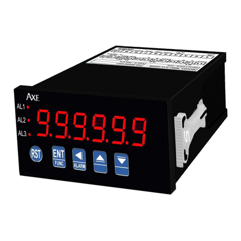
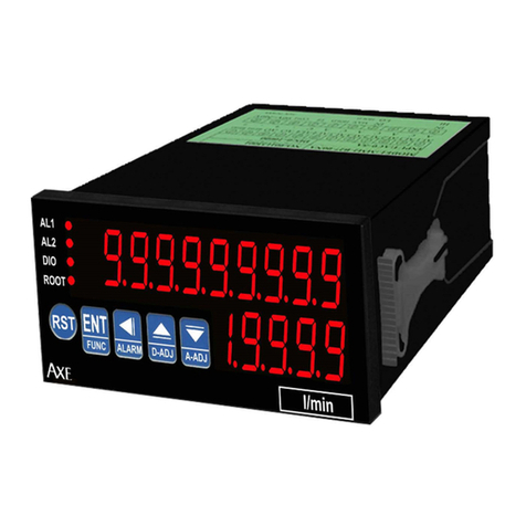
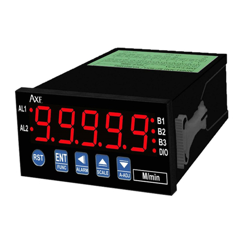
AXE MMRH Series User manual

Rev.1.1
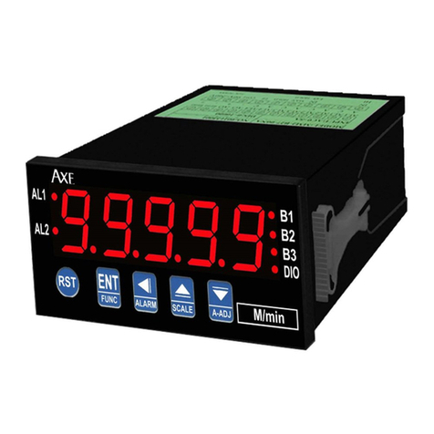
AXE Microprocess RPM & Line-speed maths controller meter MMRH Series
■Features
◎Accept more type sensors(switch,encoder,proximity
switch,…etc)finish RPM/LINE SPEED transmit ◎16BIT DAC analog output can be modified,
◎Accuracy 0.03% F.S. ◎Four alarm function
◎Input range(0~200KHz) ◎0.8" highlight display
◎Readout range(-19999~99999) ◎RS485 Communication interface,Protocol MODBUS RTU MODE
◎RPM/LINE or LINE-SPEED unit can be modified ◎BAUD RATE:38400/19200/9600/4800/2400
◎Daul input math function, B-A,B/A,(B/A)-1,1-(B/A),B/(A+B)
◎Decimal point can be modified
◎Input pulse of revolution can be modified(1~99999) ◎Man-machine interface,easy to operate
◎Diameter(LINE-SPEED)/scale(RPM) can be modified
(0.0001~9.9999) ◎EEPROM Saving,data safekeeping about 10 years
◎Display avrage times can be modified(1~99) ◎Modified inside parameter,must have pass code
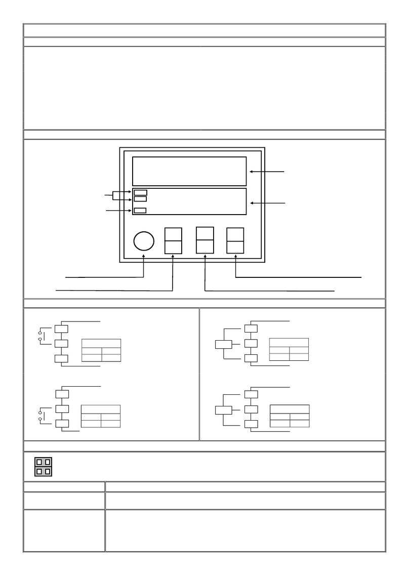
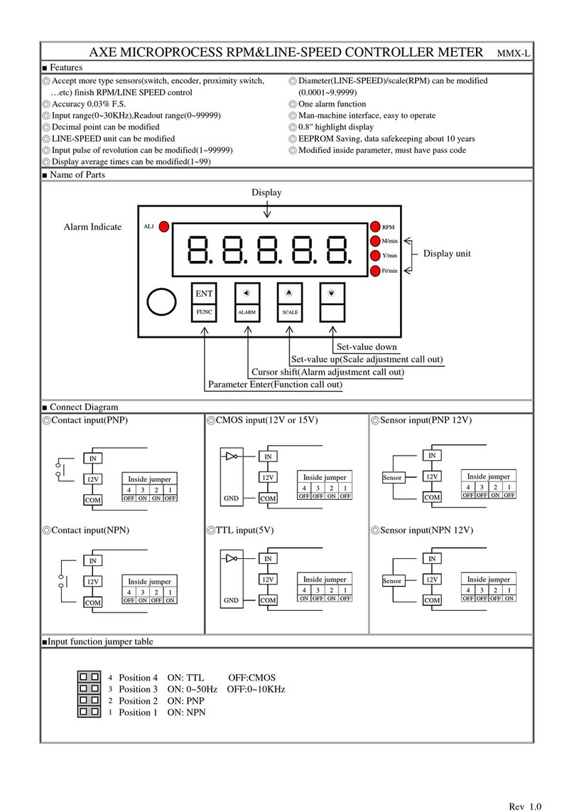
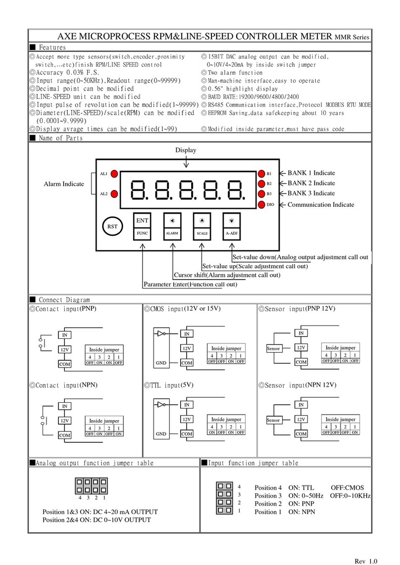
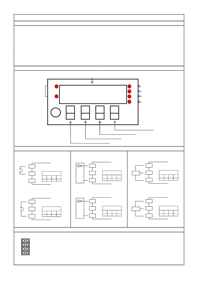
■Name of Parts
■Connect Diagram ■Input function jumper table
◎Contact input (PNP) ◎Sensor input (PNP 5V/12V)
◎Contact input (NPN) ◎Sensor input (NPN 5V/12V) Position 1 ON:IN(B) NPN
Position 3 ON:IN(A) NPN
Key Introduce Operation Manual
Key Function 1.In normal display,The key function is call out setting group
2.In parameter setting page,The key function is data Enter , and goto next page
Key Function 1.In normal display,The key function is call out alarm value setting page
2.Into parameter setting page,the parameter mark&data is alternate display,If need modify data can
press shift key into setting procedure,The display is lock parameter data,this time must let off key
about 0.2 sec,press again,the cursor(twinkle express)is cycle moving left.
(Key Response about 0.2
sec)
Key Function 1.In normal display,The key function is call out adjustment display scale page
2.Into parameter setting page,the parameter mark&data is alternate display,If need modify data can
press up key into setting procedure,The display is lock parameter data,this time must let off key
about 0.2 sec,press again,the parameter data will increment. (Key Response about 0.2 sec)
DIO
AL1
AL3
AL4
AL2
Alarm Indicate
Display
Parameter Enter
(
Function call out
)
Set-value up(Scale adjustment call out)
Set-value down(Analog output adjustment call out)
Cursor shift(Alarm adjustment call out)
ENT
FUNC
E
ALARM
D-ADJ
A-ADJ
Communication Indicate
AZ
No Use
1
2
3
4
COM
IN
12V
Inside jumper
1
2
3
4
OFF
O
FF
OFF
OFF
Sensor
COM
IN
12V
Inside jumper
1
2
3
4
ON
OFF
O
N
OFF
Sensor
COM
IN
12V
Inside jumper
1
2
3
4
OFF
O
FF
O
FF
OFF
COM
IN
12V
Inside jumper
1
2
3
4
ON
OFF
ON
OFF

Rev.1.1
Key Function 1.In normal display,The key function is call out adjustment analog output ZERO&SPAN page
2.Into parameter setting page,the parameter mark&data is alternate display,If need modify data can
press down key into setting procedure,The display is lock parameter data,this time must let off key
about 0.2 sec,press again the parameter data will decrement. (Key Response about 0.2 sec)
&
Key Function In setting group or setting page press
&
key return normal display,but if in setting page the
modify data will be lost
No Key in anything In setting group or setting page no key in anything about 2 minutes,return normal display,but if in
Setting page the modify data will be lost
Step Parameter Mark Description
Parameter Mark
Operation Manual
1
Normal display
Press
/FUNC key into P.COD setting page
2
P.COD(Pass code input page)
1.Key in 5 digit pass code with
or
or
key
2.Press
key,the pass code is right into setting group , otherwise
return normal display
SYS(System setting group)
ROP(Alarm setting group)
AOP
(Analog output setting group)
3
DOP
(Communication setting group)
1.Select setting group with
key
2.Press
key into setting page of selection setting group
4
SYS(System setting group)
Press key decideSYS setting group , press key into Dp setting
page
4-1
DP(Decimal Point setting
page)
Default = 0
1.Decide decimal point position with
or
key (0 to 4)
2.Press
key enter data and into CNTS setting page
4-2
CNTS(Count Rates Select)
Default = 200KHZ
1.Decide Count Rates Select with or key (50HZ,500HZ,200K
HZ)
2. Press key enter data and into TYPE setting page
4-3
TYPE(Display Type)
Default = RPM
1.Decide display type with
or
key(RPM/LINE)
2.Press
key enter data,If select LINE into UNIT setting page,
otherwise into PPR-A setting page
4-4
UNIT(Line Speed Unit)
Default = METER
1.Decide line speed unit with
or
key(METER/FOOT/YARD)
2.Press
key enter data and into PPR-A setting page
4-5
PPR-A(Pulse Per Revolution
of input A)
Default = 1
1.Decide pulse per revolution of input A with
&
&
key(1~99999)
2.Press
key enter data and into PPR-B setting page
4-6
PPR-B(Pulse Per Revolution
of input B)
Default = 1
1.Decide pulseper revolution of input B with
&
&
key(1~99999)
2.Press
key enter data and into MODE setting page
4-7
MODE(Mode)
Default = A
1.Decide display mode with or key
A (Display value of input A)
B (Display value of input B)
B-A (Display value of B-A)
(B/A)x100 (display value of (B/A)*100)
(B/A-1)x100 [display value of ((B/A)-1)*100]
(B/(A+B))x100 [display value of (B/(A+B))x100]
(1-B/A)x100 [display value of (1-(B/A))*100]
1A2B (Display value of input +A)(A lead B)(Max.25KHz)
(Display value of input -A)(B lead A)(Max.25KHz)
2.Press
key enter data and into TBASE setting page
4-8
TBASE (Sampling Time
Base)
Defaul t = 0.1
1.Decide sampling time base with
&
&
key(0.1~99.9sec)
2.Press
key enter data and into AVG setting page
4-9
AVG (Display Average
times)
Default = 1
1.Decide display average times with
&
&
key(1~99)
2.Press
key enter data and into CODE setting page
4-10
CODE(Pass Code)
Default = 0
1.Decide pass code with
&
&
key(0~99999)
2.Press
key enter data and into LOCK setting page

Rev.1.1
4-11
LOCK(Panel Lock)
Default = NO
1.Decide panel lock with
&
key(NO or YES)
2.Press
key enter data and return SYS setting group
5
ROP(Alarm setting group)
Press
key decide ROP setting group,press
key into ACT1 setting
page
5-1
ACT1(Alarm Active 1 setting
page )
Default = HI
1.Decide active 1 with
or
key(HI or LO)
2.Press
key enter data and into ACT2 setting page
5-2
ACT2(Alarm Active 2
setting
page )
Default = HI
1.Decide active 2 with
or
key(HI or LO)
2.Press
key enter data and into ACT3 setting page
5-3
ACT3(Alarm Active 3
setting
page )
Default = HI
1.Decide active 3 with
or
key(HI or LO)
2.Press
key enter data and into ACT4 setting page
5-4
ACT4(Alarm Active 4
setting
page )
Default = HI
1.Decide active 4 with
or
key(HI or LO)
2.Press
key enter data and into HYS1 setting page
5-5
HYS1(Alarm Hysteresis 1
setting page)
Default = 0
1.Decide Hysteresis 1 with
or
or
key(0~999)
2.Press
key enter data and into HYS2 setting page
5-6
HYS2(Alarm Hysteresis 2
setting page)
Default = 0
1.Decide Hysteresis 2 with
or
or
key(0~999)
2.Press
key enter data and into HYS3 setting page
5-7
HYS3(Alarm Hysteresis 3
setting page)
Default = 0
1.Decide Hysteresis 3 with
or
or
key(0~999)
2.Press
key enter data and into HYS4 setting page
5-8
HYS4(Alarm Hysteresis 4
setting page)
Default = 0
1.Decide Hysteresis 4 with
or
or
key(0~999)
2.Press
key enter data and into DEL1 setting page
5-9
DEL1(Alarm Delay 1 setting
page)
Default = 0
1.Decide delay 1 with
or
or
key(-99.9~99.9 sec)
2.Press
key enter data and into DEL2 setting page
Note:-0.1 ~ -99.9
sec = Alarm active time
0.1 ~ 99.9 sec = Alarm delay time
5-10
DEL2(Alarm Delay 2 setting
page)
Default = 0
1.Decide delay 2 with
or
or
key(-99.9~99.9 sec)
2.Press
key enter data and into DEL3 setting page
Note:-0.1 ~ -99.9
sec = Alarm active time
0.1 ~ 99.9 sec = Alarm delay time
5-11
DEL3(Alarm Delay 3 setting
page)
Default = 0
1.Decide delay 3 with
or
or
key(-99.9~99.9 sec)
2.Press
key enter data and into DEL4 setting page
Note:-0.1 ~ -99.9
sec = Alarm active time
0.1 ~ 99.9 sec = Alarm delay time
5-12
DEL4(Alarm Delay 4 setting
page)
Default = 0
1.Decide delay 4 with
or
or
key(-99.9~99.9 sec)
2.Press key enter data and return ROP setting group
Note:-0.1 ~ -99.9
sec = Alarm active time
0.1 ~ 99.9 sec = Alarm delay time
6
AOP(Analog output setting
group)
Press
key decide AOP setting group , press
key into ANLO
setting page
6-1
ANLO(A/O Zero According
to Display setting page)
Default = 0
1.Decide ANLO with
or
or
key(-19999~99999)
2.Press
key enter data and into ANHI setting page
6-2
ANHI(A/ O Span According
to Display setting page)
Default = 99999
1.Decide ANHI with
or
or
key(-19999~99999)
2.Press
key enter data and return AOP setting group
7
DOP(Communication setting
group)
press
key decide DOP setting group,press
key into ADDR
setting page

Rev.1.1
7-1
ADDR(Communication –Add
ress setting page )
Default = 0
1.Decide address with
or
or
key(0~255)
2.Press
key enter data and into BAUD setting page
7-2
BAUD(Communication Baud
Rate setting page)
Default = 19200
1.Decide baud rate with
or
key(38400,19200,9600,4800,2400)
2.Press
key enter data and into PARI setting page
7-3
PARI(Communication Parity
Check setting page)
Default = n82
1.Decide parity check with
or
key(n82,n81,even,odd)
2.Press
key enter data and return DOP setting group
Step Parameter mark description Parameter mark
Operation manual
8
Normal display
Press
/ALARM key about 3 sec,into AL1 1setting page
8-1
AL1 (Alarm value 1 setting
page)
Default = 0
1.Decide alarm value 1 with
or
or
key(-19999~99999)
2.Press
key enter data and into AL2 setting page
8-2
AL2 (Alarm value 2 setting
page)
Default = 0
1.Decide alarm value 2 with
or
or
key(-19999~99999)
2.Press
key enter data and into AL3 setting page
8-3
AL3 (Alarm value 3 setting
page)
Default = 0
1.Decide alarm value 3 with
or
or
key(-19999~99999)
2.Press
key enter data and into AL4 setting page
8-4
AL4 (Alarm value 4 setting
page)
Default = 0
1.Decide alarm value 4 with
or
or
key(-19999~99999)
2.Press
key enter data and return normal display
Step Parameter mark description Parameter mark
Operation manual
9
Normal display
Press
/D-ADJ key about 3 sec,into SCL-A setting page
9-1
SCL-A (Display Scale A
setting page)
Default = 1
1.Decide scale A with
or
or
key(0.0001~9.9999)
2. Press
key enter data and into SCL-B setting page
9-2
SCL-B (Display Scale B
setting page)
Default = 1
1.Decide scale B with
or
or
key(0.0001~9.9999)
2.Press
key enter data and return normal display
Step Parameter mark description Parameter mark
Operation manual
10
Normal display
Press
/A-ADJkey about 3 sec,into AZERO adjustment page
10-1
AZERO(Analog Output
Zero Adjustment page)
Default = 0
1.Adjustment analog output zero with
or
or
key(±6000)
2.Press
key enter data and into ASPAN adjustment page
10-2
ASPAN(Analog Output
Span Adjustment page)
Default = 0
1.Adjustment analog output span with
or
or
key(±6000)
2.Press
key enter data and return normal display
Appendix
Error Mark description Error Mark Analyze & Description
1
Input over range error
detect
Input signal over range(0~200KHz)
2
Display over range error
detect
Display over range(99999)
3
Display under range error
detect
Display under range (-19999)
4
EEPROM error detect
1.External interference when EEPROM read/write
2.EEPROM write over 1 million times(guarantee 10 years)
Please power reset,if still display E-00,doing following step:
1.E-00 & No alternate display for inquire reset EEPROM
2.Decide Yes with or key,press key return normal display
3.EEPROM was reset,Please follow step 1~10 set again

Rev.1.1
MMRH Modbus RTU Mode Protocol Address Map
Data format 16Bit/32Bit, sign bit 8000~7FFF(-32768~32767),80000000~7FFFFFFF(-2147483648~2147483647)
Address
Name
Description Accept
0000
DP Decimal Point,Input Range 0000~0004 (0~4)(0:100,1:10-1,2:10-2,3:10-3,4:10-4) R/W
0001
TYPE
Display Type,Input Range 0000~0001 (0~1) (0:RPM,1:LINE) R/W
0002
LOCK
Panel Lock,Input Range 0000~0001 (0~1)(NO/YES) R/W
0003
CNTS
Count Rates Select,Input Range 0000~0002 (0~2) (0:50HZ,1:500HZ,2:200KHZ) R/W
0004
UNIT
Line Speed Unit,Input Range 0000~0002 (0~2) (0:METER,1:FOOT,2:YARD) R/W
0005
MODE
Mode,Input Range 0000~0007 (0~7)(0:A,1:B,2:B-A,3: (B/A)x100,4: (B/A-1)x100,5: (B/(A+B))x100,
6:(1-B/A)x100), 7:1A2B R/W
0006
TBASE
Sampling Time Base,Input Range 0001~03E7 (0.1~99.9 sec.) R/W
0007
AVG Display Average times,Input Range 0001~0063 (1~99) R/W
0008
ACT1
Alarm Active 1,Input Range 0000~0001(0~1) (0:HI,1:LO) R/W
0009
ACT2
Alarm Active 2,Input Range 0000~0001(0~1) (0:HI,1:LO), R/W
000A
ACT3
Alarm Active 3,Input Range 0000~0001(0~1) (0:HI,1:LO) R/W
000B
ACT4
Alarm Active 4,Input Range 0000~0001(0~1) (0:HI,1:LO) R/W
000C
HYS1
Alarm hysteresis 1,Input Range 0000~03E7 (0~999) R/W
000D
HYS2
Alarm hysteresis 2,Input Range 0000~03E7 (0~999) R/W
000E
HYS3
Alarm hysteresis 3,Input Range 0000~03E7 (0~999) R/W
000F
HYS4
Alarm hysteresis 4,Input Range 0000~03E7 (0~999) R/W
0010
DEL1
Alarm Delay 1,Input Range FC19~03E7 (-99.9~99.9) R/W
0011
DEL2
Alarm Delay 2,Input Range FC19~03E7 (-99.9~99.9) R/W
0012
DEL3
Alarm Delay 3,Input Range FC19~03E7 (-99.9~99.9) R/W
0013
DEL4
Alarm Delay 4,Input Range FC19~03E7 (-99.9~99.9) R/W
0014
ADDR
Communication Address,Input Range 0000~00FF (0~255) R/W
0015
BAUD
Communication Baud Rate,Input Range 0000~0004 (0~4)( 0:38400,1:19200,2:9600,3:4800,4:2400) R/W
0016
PARI
Communication Parity Check,Input Range 0000~0003 (0~3)(0:N82,1:N81,2:EVEN,3:ODD) R/W
0017
A_ZERO
Analog Output Zero Adjust,Input Range E890~1770 (-6000~6000) R/W
0018
A_SPAN
Analog Output Span Adjust,Input Range E890~1770 (-6000~6000) R/W
0019
CODE
Pass Code,Input Range 00000000~0001869F (0~99999)high word R/W
001A
Pass Code,Input Range 00000000~0001869F (0~99999)low word R/W
001B
PPR-A
Pulse Per Revolution of input A,Input Range 00000001~0001869F (1~99999)high word R/W
001C
Pulse Per Revolution of input A,Input Range 00000001~0001869F (1~99999)low word R/W
001D
PPR-B
Pulse Per Revolution of input B,Input Range 00000001~0001869F (1~99999)high word R/W
001E
Pulse Per Revolution of input B,Input Range 00000001~0001869F (1~99999)low word R/W
001F
SCL-A
Display Scale A,Input Range 00000001~0001869F (0.0001~9.9999)high word R/W
0020
Display Scale A,Input Range 00000001~0001869F (0.0001~9.9999)low word R/W
0021
SCL-B
Display Scale B,Input Range 00000001~0001869F (0.0001~9.9999)high word R/W
0022
Display Scale B,Input Range 00000001~0001869F (0.0001~9.9999)low word R/W
0023
ANLO
Analog Output Zero According to Display,Input Range FFFFB1E1~0001869F (-19999~99999)high word R/W
0024
Analog Output Zero According to Display,Input Range FFFFB1E1~0001869F (-19999~99999)low word R/W
0025
ANHI
Analog Output Span According to Display,Input Range FFFFB1E1~0001869F (-19999~99999)high word R/W
0026
Analog Output Span According to Display,Input Range FFFFB1E1~0001869F (-19999~99999)low word R/W
0027
AL1 Alarm 1,Input Range FFFFB1E1~0001869F (-19999~99999)high word R/W
0028
Alarm 1,Input Range FFFFB1E1~0001869F (-19999~99999)low word R/W
0029
AL2 Alarm 2,Input Range FFFFB1E1~0001869F (-19999~99999)high word R/W
002A
Alarm 2,Input Range FFFFB1E1~0001869F (-19999~99999)low word R/W
002B
AL3 Alarm 3,Input Range FFFFB1E1~0001869F (-19999~99999)high word R/W
002C
Alarm 3,Input Range FFFFB1E1~0001869F (-19999~99999)low word R/W
002D
AL4 Alarm 4,Input Range FFFFB1E1~0001869F (-19999~99999)high word R/W
002E
Alarm 4,Input Range FFFFB1E1~0001869F (-19999~99999)low word R/W
002F
DISP Display Value, Display Range FFFFB1E1~0001869F (-19999~99999)high word R
0030
Display Value, Display Range FFFFB1E1~0001869F (-19999~99999)low word R
0031
STATUS
Status,Display Range 0000~007F(0~127)Bit0:AL1,Bit1:AL2,Bit2:AL3,Bit3:AL4,Bit4:DOFL,Bit5:-DOFL,Bit6:IOFL
0000~007F(0~127)Bit0:AL1,Bit1:AL2,Bit2:AL3,Bit3:AL4,Bit4:DOFL,Bit5:-DOFL,Bit6:IOFL R
Other AXE Measuring Instrument manuals
Popular Measuring Instrument manuals by other brands

Caen
Caen DT5740 Technical information manual

Savant
Savant SmartEnergy SEM-1024 Quick reference guide

PEWA
PEWA Questemp II instruction manual

Clarion
Clarion Drive Eye manual

MONARCH INSTRUMENT
MONARCH INSTRUMENT ACT-3X User manual and reference guide

Saunier Duval
Saunier Duval MiLink Plus installation instructions