ELMARK AN-100 User manual

AN-Ø100
AN-Ø120
MODEL DESCRIPTION
Standard
Pull
switch Flap Flange
PS - PULL SWITCH
V - LAPF
PSV - PULL SWITCH + FLAP
F - FLANGE
VF - FLAP+FLANGE
INSTRUCTIONS FOR INSTALLATION AND USE
ENG

Read these instructions carefully before use and keep it for future references.
The installation and the adjustment of the ventilator can only be done by competent persons, trained to work with electric
systems up to 1000V, who have read the given instructions for installation, adjustment and use.
Characteristics of the power network to which the device is connected have to be within norms (standards) and effective
regulations. The electrical installation must feature a device for the automatic protection of network. The appliance needs
to be connected through phase switch with at least 3 mm distance between contacts. Check before the installation whether
the parts of the ventilator (propeller, ventilator body and mask) are without signs of damage, and, in particular, that there
are no small objects in the operating part of the ventilator (area of rotation of propeller blades), which could damage the
blades. The device must not be used for the purposes for which it is not intended and any modifications or changes are
strictly prohibited.
This appliance is not intended for use by children or persons with impaired physical, mental or sensory abilities, or by
persons with insufficient knowledge and experience, unless they are supervised by a person responsible for their safety or
have been given instructions for safe use of the appliance. Children must be under supervision of adults in order to prevent
playing with the appliance. Also, cleaning and user maintenance must not be carried out by children under the age of 8 and
without supervision.
If joint exhaust outlet is used, it is necessary to take measures to prevent permeating of smoke, unburnt gases and other
combution products. Possibility of reverse flow of gases from appliances using gas or open flame needs to be eliminated.
The air that is taken out of the premise must contain no dust or other solid particles, as well as sticky substances and
fibrous materials. The appliance must not be used in the premises with flammable substances or evaporations (such as
petrol, benzene, inscticides etc.).
The appliance should not be covered and fresh air flow should not be obstructed. Air flow through the openings in the mask
to the operating part of the ventilator should be optimal in order to secure the parameters and the stated technical
characteristics. Also, sitting on the appliance or putting objects on it is not allowed.
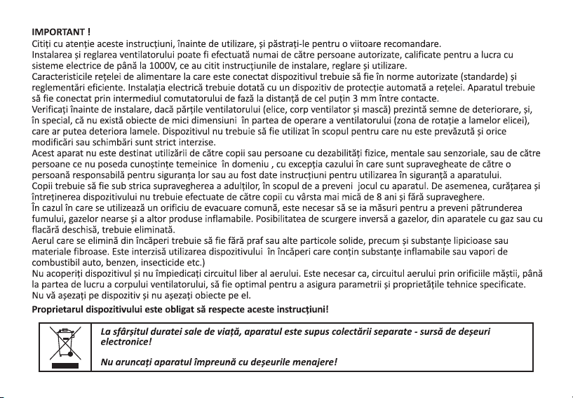
At the end of its working life, the appliance is subject to source-separated collection of electric
waste!
Do not dispose of the appliance together with communal waste!
IMPORTANT!
The owner of the appliance is obliged to comply with these instructions!

Type Model description
AN-Ø100
Motor
class II
15W
Ventilator model Technical characteristics
AN-Ø120PS
AN-Ø120PSV
AN-Ø120VF
AN-Ø120
AN-Ø120V
AN-Ø120F
AN-Ø100PS
AN-Ø100PSV
AN-Ø100VF
AN-Ø100
AN-Ø100V
AN-Ø100F
AN-Ø120
Motor
class II
20W
MAIN TECHNICAL CHARACTERISTICS
The ventilator is connected to electric power network (electric current) of AC voltage of 230 V and 50 Hz frequency.
When it comes to electric shock protection, the ventilator belongs to Class II (230 V / 50 Hz).
Labelling of certain ventilator models and meanings of symbols are shown in the table below, while the schematic
overview, horisontal and mounting dimensions, as well as the construction characteristics are shown in tables 1 and 2.
O O
The ventilator is intended for exploitation in air temperatures in the range from +1 C to +40 C.
Noise level on 3m distance does not exceed 45dB.
pull switch
pull switch+flap
flap+flange
standard
flap
flange
pull switch
pull switch+flap
flap+flange
standard
flap
flange
- Voltage: 230V
- Speed: 2500 rpm
- Power:15W
3
- Air flow:98 m/h
- Noise level:41dB (À)
- Mass: 0,5kg
- Protection: IP-X4
- Voltage: 230V
- Speed: 2450 rpm
- Power:20W
3
- Air flow:190 m/h
- Noise level:43dB (À)
- Mass: 0,65kg
- Protection: IP-X4

Table 2.
AN-Ø100
AN-Ø120
TYPE
Pa
30
20
0
40
10
Pe(mmcda)
3
2
0
4
1
AN-Ø100
3
Q(m /h)
0.005 0.011 0.0220 0.016
20 40 800 60
0.027
100
3
Q(m /s)
Pa
50
20
0
60
Pe(mmcda)
5
2
0
6
AN-Ø120
3
Q(m /h)
0.005 0.011 0.022
0
0.016
40 80 1600 120
0.027
200
3
Q(m /s)
20 60 100 140 180
10 1
30 3
40 4
0.033 0.038 0.044 0.05 0.055
Pe - (mmcda) i PàPressure 3 3
Q- Air flow (m/h) i(m /s)
Table 1.
Dimensions (mm)
ØA
98
118
B
153
180
C
45
50
D
37
37
B
B
A
CD

The ventilators are designed to ventilate housing or office space.
They are used in premises and in places where spreading of humidity and
odours needs to be prevented. They are not intended for use in work
O
environments and housing facilities where air temperature exceeds 40 C.
PURPOSE OF THE VENTILATOR
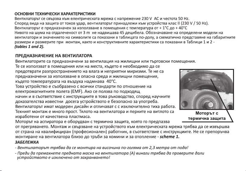
The installation and connecting of the appliance to power supply should be carried out by a qualified (competent)
person, in accordance with the instructions. Installation in the vicinity of chimney or heating pipes is not
recommended - shema 1.
The appliance complies with all electromagnetic field (EMF) standards.
If the appliance is operated properly and in accordance with the instructions
given in this manual, it is safe for use, according to scientific evidence available
nowadays.
The ventilators are with modern design and very silent operation.
Their installation is very simple Its installation is very simple and quick.
The ventilator body, mask and blades are made of quality plastic.
The ventilator engine has a thermal equipment which prevents engine overheating.
MOTOR WITH
THERMAL PROTECTION
VENTILATOR INSTALLATION
Onto ceiling On window
(flange)
Into a wall opening
scheme 1

The appliance must be connected with only one phase from main power supply of the indicated voltage and frequency,
shown on the plate with the technical characteristics of the ventilator. The electrical installation must have a phase
switch with at least 3 mm distance between contacts.
CONNECTING TO POWER SUPPLY
Place the ventilator AN-Ø100 or AN-Ø120 into pre-drilled opening of an adequate size in the wall or the ceiling.
Remove front mask (A), releasing the mask holder (1) with the tip of the screwdriver until it is released, and
then pull the mask toward yourself.
The ventilator body (D) should be put into the opening on the wall or the ceiling. The ventilator frontal part (B) should
be positioned and fixed using the classical method with wall plugs and screws (2) or by fixing with a flange (4) on the
back side (in case of installation on window).
A
1
1
D
B
3
C
4
2
NOTE:
- The ventilator must be installed on the height over 2.3 m from floor level!
-Before removal of the ventilator front mask (A) always check whether the appliance is disconnected from power supply!
FIGURE 1.Ventilator components

The electrical connection is achieved by connecting the power cable with the connector (C), blue wire with N contact
and brown or black wire with L contact (fig 2). Press mask (A) on the frontal part of the ventilator (B), until it is firmly
caught by the mask holder (1) (fig 1). The appliance must be connected with the power cable with the cross section of
2
at least 1.0 - 1.5 mm .
~
L
N
~
L
N
USER MAINTENANCE
The ventilator maintenance works are conducted only after the appliance is disconnected from power supply.
Cleaning should be done with a soft cloth and a small brush using water solution of a mild detergent. Avoid contact
between liquid and electric components. After cleaning, surfaces need to be well dried before the appliance is used
again.
STORING
The appliances should be stored i.e. kept in an aired premise at temperatures from +5 °C to + 40 °C and at relative air
humidity lower than 80% (at T = 25 °C), in original production packaging.
FIGURE 2.Wiring diagram
WITH OR
WITHOUT FLAP
WITH PULL
SWITCH


This manual suits for next models
11
Table of contents
Other ELMARK Fan manuals


