ELMEKO PM 100 User manual

3
INHALTSVERZEICHNIS TABLE OF CONTENTS
Anwendung .................................................................................................................................................................................................4
Technische Daten......................................................................................................................................................................................4
Eigenschaften ............................................................................................................................................................................................. 5
Leistungsdiagram......................................................................................................................................................................................5
Lieferumfang...............................................................................................................................................................................................5
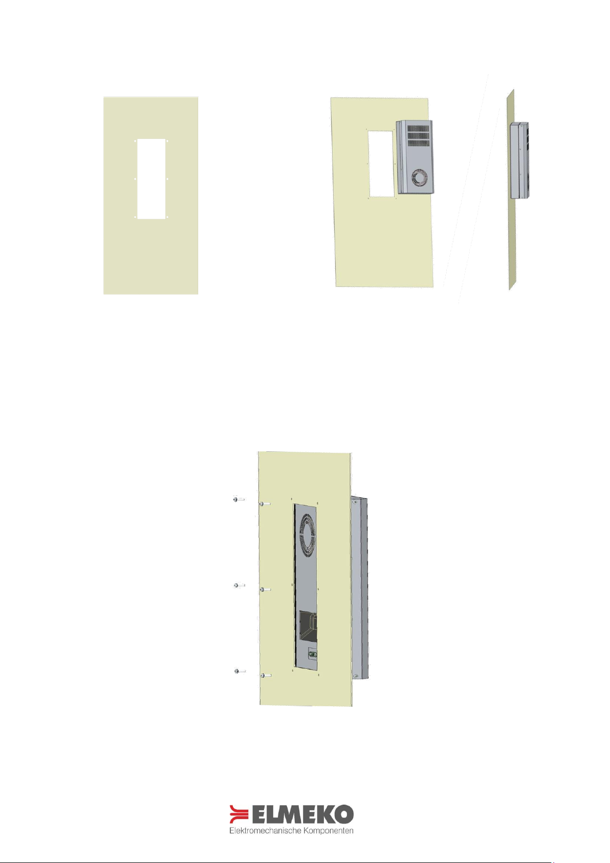
Abmessungen / Montageausschnitt..................................................................................................................................................6
Montage........................................................................................................................................................................................................6
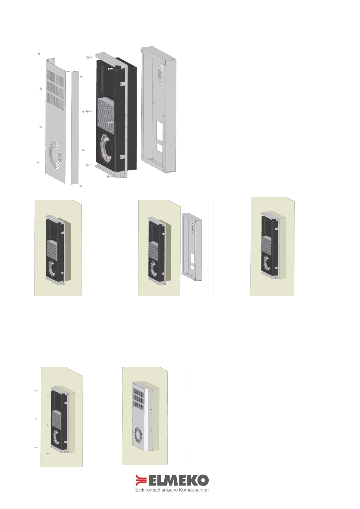
Anbau.............................................................................................................................................................................................................7
Teilanbau......................................................................................................................................................................................................8
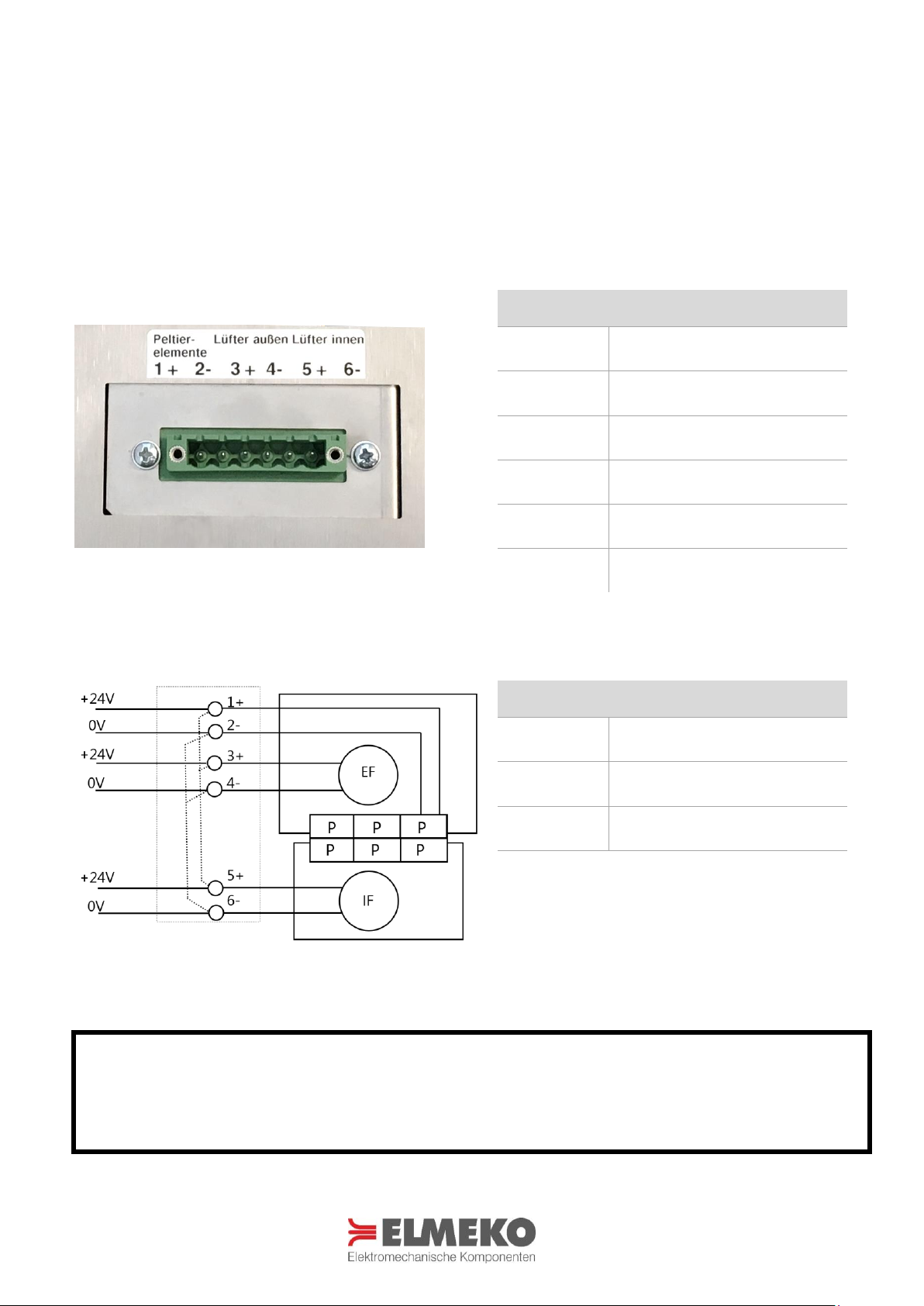
Schaltbild......................................................................................................................................................................................................8
Elektrischer Anschluss .............................................................................................................................................................................9
Anschlussbeispiel Kühlen mit TES 60* ............................................................................................................................................10
Anschlussbeispiel Heizen und Kühlen mit TRP 205* ................................................................................................................10
Zubehör.......................................................................................................................................................................................................11
Sicherheitshinweise ................................................................................................................................................................................11
Wartung und Pflege...............................................................................................................................................................................12
Garantieerklärung ...................................................................................................................................................................................12
Application...................................................................................................................................................................................................4
Technical Data ............................................................................................................................................................................................ 4
Features.........................................................................................................................................................................................................5
Performance curve....................................................................................................................................................................................5
Delivery contents.......................................................................................................................................................................................5
Dimensions / Installation cutout.........................................................................................................................................................6
Installation ...................................................................................................................................................................................................6
External mounting .................................................................................................................................................................................... 7
Partial internal mounting.......................................................................................................................................................................8
Wiring diagram .......................................................................................................................................................................................... 8
Electric installation....................................................................................................................................................................................9
Connection example cooling with TES 60*...................................................................................................................................10
Connection example heating and cooling with TRP 205* ......................................................................................................10
Accessories ................................................................................................................................................................................................11
Safety instructions ..................................................................................................................................................................................11
Care and maintenance ..........................................................................................................................................................................12
Guarantee bond.......................................................................................................................................................................................12

4
ANWENDUNG APPLICATION
Die Peltier-Kühlgeräte wurden zur Klimatisierung von Schaltschränken und Wandgehäusen, sowie für Displays
und Großanzeigen entwickelt. Sie zeichnen sich aus durch ihre schnelle und flexible Montage, Zuverlässigkeit,
geringen Wartungsaufwand und ihrer optimalen ästhetischen Integration. Sie sind erhältlich mit einer
Kühlleistung von bis zu 100 Watt. Durch das Edelstahlgehäuse wird ein Outdooreinsatz auch in rauer Umgebung
ermöglicht. Die Kühlgeräte erreichen die Schutzart IP55. Weitere Vorteile sind die Eignung für mobilen Betrieb
und die Möglichkeit, die Geräte in jeder Lage zu montieren, da diese ohne Kältemittel und Vibrationsfrei
arbeiten. Der hohe Wirkungsgrad trägt zusätzlich zur Umweltfreundlichkeit bei. Mit dem passenden Regler ist
Kühl- und Heizbetrieb möglich.
The Peltier coolers are developed for cooling of small enclosures and electronic cases, as well as industrial PC
and large displays. They are characterized by their quick and flexible assembly, reliability, low-maintenance and
their optimal aesthetic design. They can be supplied with cooling capacities of up to 100 watts. The stainless-
steel housings allows outdoor use even in harsh environments. The coolers reach degree of protection up to
IP55. Further advantages are the suitability for mobile use and the possibility to install the thermoelectric coolers
in every position, because they work without liquid refrigerants and without vibrations. The high efficiency
contributes additionally to the eco-friendliness. With the matching controller cooling and heating is possible.
TECHNISCHE DATEN TECHNICAL DATA
Bezeichnung Type
PM 100
Artikelnummer Part number
40 M10 570
Betriebsspannung
Operating voltage
24 V DC
Eingangs-Spannungsbereich
Input voltage range
16 - 28 V DC
Stromaufnahme
Amperage
6,5 A
Anlaufstrom
Starting current
8,5 A
Vorsicherung
Fuse
10 A (T)
Kühlleistung bei ∆t= 0 Kelvin
Cooling capacity at ∆t= 0 Kelvin
100 W
Heizleistung
Heathing capacity
180 W
Nennleistung
Nominal power
156 W
Schalldruck
Sound presure
72 dB(A) @1m
Luftvolumenstrom
Air volume flow
120 m³/h
Schutzart Außen / Innen
Degree of protection outside / inside
IP55 / IP20
Lebensdauer
Service life
60.000 h
Gewicht
Weight
5300 gr.
Einsatztemperatur
Operating temperature
-25 °C … +50 °C
Zulassungen
Approval
CE

5
EIGENSCHAFTEN FEATURES
LEISTUNGSDIAGRAM PERFORMANCE CURVE
LIEFERUMFANG DELIVERY CONTENTS
-Schaltschrankkühlung mit Peltiertechnik
-Anbau und Teileinbau ohne weiteres Zubehör
-Robustes Edelstahlgehäuse
-Elegante flache Bauform
-Getrennter Innen- und Außenkreislauf
-Hochleistungskühlkörper
-Optimierte Luftführung
-Gerichteter Kaltluftstrom
-Heiz- oder Kühlbetrieb
-Steckbare Anschlussteckleiste
-Enclosure cooling with Peltier technology
-Extension and installation without additional accessories
-Robust stainless-steel housing
-Elegant flat design
-Separate internal and external circulation
-High-performance heatsinks
-Optimized airflow
-Directional cold air flow
-Heating or cooling operation
-Plug-in terminal
Mit dem QR-Code haben Sie direkten Zugang zur
umfangreichen Berechnung der benötigten Kühl- und
Heizleistung. Die Berechnungssoftware DELTA T bietet
ihnen dazu eine gute Möglichkeit, Ihr Projekt genau
zu bewerten.
With the QR code you have direct access to the
extensive calculation of the required cooling and
heating capacity. The calculation software DELTA T
offers you a good opportunity to evaluate your
project precisely.
Abführbare Verlustleistung / Heat dissipation capacity [W]
Innentemperatur / Inside temperature [°C]
-Peltier-Kühlgerät
-Befestigungsschrauben
-Betriebsanleitung
-6-polige Anschlusssteckleiste
-Thermoelectric cooler
-Fastening screws
-Instruction manual
-6-pole pluggable terminal block

6
ABMESSUNGEN / MONTAGEAUSSCHNITT DIMENSIONS / INSTALLATION CUTOUT
MONTAGE INSTALLATION
Für die Montage ist ein Ausschnitt in Türe, Seitenwand, Rückwand oder Dach des Gehäuses erforderlich. Der
Montageausschnitt muss der Montageposition entsprechend sein. Die Montageposition ist so zu wählen, dass
der Luftstrom des Peltier-Kühlgeräts die Temperierung der Komponenten unterstützt. Ein optimaler Luftstrom
wird bei senkrechter Einbaurichtung erreicht. Direktes Anströmen von temperaturempfindlichen Einbauten mit
Kalt- oder Warmluft ist zu vermeiden. Die Lufteintritts- und Luftaustrittsöffnungen sind freizuhalten. Nur so kann
sichergestellt werden, dass die maximale Kühlleistung zur Verfügung steht. Kühlgeräte können als Anbau oder
auch als Teilanbau montiert werden. Der Montageausschnitt ist jeweils gleich. Für welche Montagemöglichkeit
Sie sich entscheiden, hängt letztlich vom Platzbedarf innerhalb und außerhalb des Schaltschranks ab und hat
keinen Einfluss auf die Kühlleistung.
For installation a cutout is necessary which can be done in door, side, rear or roof of the enclosure. The
mounting cutout must be according to the mounting position. The mounting position should be selected so that
the air flow of the Peltier coolers unit supports the temperature control of the components. An optimal air flow is
achieved through vertical installation. Direct oncoming of temperature-sensitive installations with cold or hot air
is to be avoided. The air inlet and air outlet openings are to be kept unhindered. Only in this way can it be
ensured that the maximum cooling power is available. Thermoelectric coolers can be mounted external or partial
internal. The mounting cutout is the same. Which mounting option you choose depends ultimately on the space
required inside and outside of the enclosure and has no influence on the cooling capacity.
Montageausschnitt für An- und
Teileinbau!
Mounting cutout for external and
partial internal mounting!
Mit dem QR-Code haben Sie direkten Zugang zur
Homepage www.elmeko.de wo der
Montageausschnitt als PDF oder DXF Datei
heruntergeladen werden kann
With the QR code you have direct access to the
homepage www.elmeko.de where the mounting
cut-out can be downloaded as PDF or DXF file
Alle Maße in mm
All dimensions in mm

7
ANBAU EXTERNAL MOUNTING
Montageausschnitt und Bohrungen nach
Zeichnung oder Bohrschablone
anfertigen
Use the drawing or a drilling template for
the mounting cutout
Ansicht von innen
View from inside
Gerät von innen mit sechs Schrauben M5 mit Unterlegscheiben befestigen
Fasten the unit from inside with six screws M5 with washers
Das Kühlgerät auf den Ausschnitt setzen
Place the cooler on the cutout

8
TEILANBAU PARTIAL INTERNAL MOUNTING
SCHALTBILD WIRING DIAGRAM
Seitliche Schrauben am Gehäuseoberteil entfernen
und das Oberteil abnehmen. Anschließend die 6
Schrauben im Rahmen entfernen und vorsichtig
das Gehäuseunterteil abziehen.
Remove the screws on the side of the housing
cover and take the cover away. Then remove the 6
screws in the frame and carefully pull off the
bottom part.
Das Kühlgerät von außen in den Montageausschnitt einsetzen und anschließend das Gehäuseunterteil von der
Schrankinnenseite ansetzen und fixieren
Insert the cooling unit from the outside into the installation cut-out and then place the bottom part of the housing
from the cabinet inside in position
Mit den 6 Schrauben von der Außenseite den
Gehäuserahmen und das Unterteil verschrauben und
anschließend das Gehäuseoberteil am Kühlgerät montieren.
Fit the housing frame and the bottom part with the 6 screws
from the outside and replace the housing cover to the
cooling unit

9
ELEKTRISCHER ANSCHLUSS ELECTRIC INSTALLATION
Für den elektrischen Anschluss ist der Schaltschrank vorher vorschriftsmäßig außer Betrieb zu nehmen. Die
Spannungsversorgung sind an die Anschlussklemmen anzuschließen (siehe Schaltbild). Es wird eine
Gleichstromspannung von 24 V DC benötigt. ACHTUNG: Bei Anschluss an Wechselspannung wird das Gerät
zerstört.
For the electrical connection, the control cabinet must first be disconnected. Connect the supply voltage to the
terminals (see wiring diagram). The power supply requires an DC voltage of 24 V DC. ATTENTION: AC current will
destroy the cooler.
Klemme
Terminal
Belegung Connection
1
Peltier Elemente +24V
Peltier-Elements +24V
2
Peltier Elemente 0V
Peltier-Elements 0V
3
Lüfter Außenkreislauf +24V
External fan +24V
4
Lüfter Außenkreislauf 0V
External fan 0V
5
Lüfter Innenkreislauf +24V
Internal fan +24V
6
Lüfter Innenkreislauf 0V
Internal fan 0V
Bezeichnung
Term
Belegung Connection
EF
Lüfter Außenkreislauf
External fan
P
Peltier Elemente
Peltier-Elements
IF
Lüfter Innenkreislauf
internal fan +24V
Klemmen 1+, 3+ und 5+ sowie die Klemmen 2-,
4- und 6- können auch zusammen ange-
schlossen werden.
Terminals 1+, 3+ and 5+ and terminals 2-, 4-
and 6- can be connected.
ACHTUNG!
Bei eingeschalteter Kühlung müssen die Lüfter Außen- und Innenkreislauf immer mit eingeschaltet sein!
ATTENTION!
External and internal fans must run if the cooling is switched on!

10
ANSCHLUSSBEISPIEL KÜHLEN MIT TES 60*
CONNECTION EXAMPLE COOLING WITH TES 60*
ANSCHLUSSBEISPIEL HEIZEN UND KÜHLEN MIT TRP 205*
CONNECTION EXAMPLE HEATING AND COOLING WITH TRP 205*
* Thermostate und Netzteil sind Zubehör und müssen separat bestellt werden
Thermostats and power supply are accessories and must be ordered separately

11
ZUBEHÖR ACCESSORIES
Bezeichnung
Type
Beschreibung Description
Artikelnummer Part number
Emparro 10
Netzteil Emparro 10
Power supply Emparro 10
42 10A 500
TES 60
Thermostat TES60
Thermostat TES60
15 TES 060
TRP 205
Thermostat TRP 205, Heizen + Kühlen
Thermostat TRP 205, heating + cooling
45 TRP 205
TRP 260
Temperatursteuerung TRP 260
Temperature control TRP 260
45 TRP 260
SICHERHEITSHINWEISE SAFETY INSTRUCTIONS
-Die Installation darf nur von autorisiertem Fachpersonal vorgenommen werden. Die landesüblichen
Richtlinien sind gemäß IEC 60364 einzuhalten
-Die technischen Daten auf dem Typenschild und in dieser Anleitung sind zu beachten
-Der Anschluss erfolgt an 24 V DC
-Anschlusskabel sind nur als Kupferleitungen zulässig
-Die maximale Umgebungstemperatur von bis zu 50 °C ist zu berücksichtigen
-Die Umgebung des Geräts darf max. Verschmutzungsgrad 2 entsprechen
-Vorschriften des EVU sind zu beachten
-Bei Beschädigung des Gehäuses oder der Anschlussleitung Spannung abschalten und alle Stecker abziehen
-Achtung! Beim Öffnen des Gerätes erlischt die Garantie
-Schutzmaßnahmen nach VDE 0100 sind sicherzustellen
-Bei der Herstellung von Montageausschnitten und Befestigungsbohrungen ist geeignete Schutzausrüstung zu
tragen.
-Luftein- und Luftaustrittsöffnungen des Gerätes dürfen nicht abgedeckt werden.
-Installation must only be carried out by qualified electrical technicians in observation of the respective national
power supply guidelines (IEC 60364)
-The technical specifications on the identification plate and in this manual, must be observed
-Supply voltage is 24 V DC
-Connection cables only as copper conductors only
-Taking into account the maximum surrounding air temperature rating of 50 °C
-The environment of the device may be maximum with pollution degree 2
-If the housing, or wire is damaged, switch off the voltage supply and disconnect all plugs
-Attention! Opening the case will void guarantee
-The safety measures according to VD 0100 have to be ensured
-Wear protective gear when cutting the mounting cut out and drilling the fastening holes.
-The air inlet and outlet openings to the unit must not be covered.
Die Entsorgung muss gemäß den jeweiligen nationalen gesetzlichen Bestimmungen erfolgen.
The disposal is to occur according to the respective national regulations.

12
WARTUNG UND PFLEGE CARE AND MAINTENANCE
-
Das Peltier-Kühlgerät ist wartungsarm
-
Führen Sie in regelmäßigen Abständen eine Sichtprüfung an den Lüftern und dem Aussenkühlkörper durch
-
In staubbelasteter Umgebung kann ein Ausblasen des Kühlkörpers mit Druckluft zur Erhaltung der
Kühlleistung erforderlich sein. Dabei muss das Gerät spannungsfrei geschaltet werden!
-
The thermoelectric cooler is low-maintenance
-
Regularly perform a visual inspection at the fans and the outer heatsink
-
Dusty environments may require a cleaning of the heatsink with compressed air to maintain the cooling
performance. Before cleaning disconnect the device from the mains!
GARANTIEERKLÄRUNG GUARANTEE BOND
Wir gewähren eine Garantiezeit von 24 Monaten ab dem Zeitpunkt der Lieferung des Gerätes bei
bestimmungsgemäßen Einsatz und unter den folgenden Betriebsbedingungen:
-Einsatz in Schaltschränken oder Gehäusen für industrielle Anwendungen
-Beachtung der auf dem Typenschild angegebenen Anschlussspannung und Anschlussleistung
Diese Garantie gilt nicht für evtl. Schäden, die dem Gerät zugefügt werden durch:
-Inbetriebnahme in ungeeigneter Umgebung, z. B. in saurer oder ätzender Atmosphäre
-Anschluss an eine andere Spannung, wie auf dem Typenschild angegeben
-Überspannung, z. B. Blitzeinschlag
-Äußere Gewaltanwendung
Die Garantie entfällt bei einer Benutzung, die nicht den Vorschriften in der Betriebsanleitung entspricht.
Im Schadensfall innerhalb der Garantiezeit übernimmt der Hersteller eine Materialgarantie, indem die fehlerhaften
Bauteile repariert oder ersetzt werden. Der Hersteller übernimmt keinerlei Verantwortung außerhalb der Reparatur
oder dem Austausch defekter Bauteile. Der Hersteller übernimmt keine Aufwendungen für Aus- und Einbau des
Gerätes, oder der Folgeschäden. Die reparierten oder ausgetauschten Bauteile verändern den Beginn oder die
Beendigung der Garantiezeit in keiner Weise.
Es liegt in der Verantwortung des Kunden, die richtige Erdung, Installation und Stromversorgung des Gerätes
entsprechend der gültigen Vorschriften sicherzustellen.
Achtung: Alle Eingriffe in das Gerät haben den Verfall der Gewährleistung und den Haftungsausschluss zur Folge!
We grant a guarantee of 24 months starting from delivery and when the operating instructions are fully complied with
and when they are used in the following conditions:
-Operation in enclosures or cabinets for industrial applications
-Power supply must be same as indicated on the identification plate
This guarantee does not cover any damage to the product due to:
-Using the product in unsuitable environment, e.g. in acid or corrosive atmospheres
-Connection to a supply voltage different from that indicated on the identification plate
-Electrical overload, e.g. through lightning strike
-Damage caused by external force
The guarantee is void with a use, which does not correspond to the regulations in the operating manual.
For each component found to be faulty during the term of the guarantee, the manufacturer will, according to its
unquestionable judgement, repair, and/or substitute the faulty components free of charge. The manufacturer is in no
way held liable except for repairing or substituting faulty products. The manufacturer is not responsible for any
additional expenses incurred for removing, handling and installation if required. The repaired or replaced products do
not change the time the guarantee starts or ends.
It is the customer’s responsibility to see to the correct protective earth connection, installation, and power supply of
the product in compliance with current standards.
Attention: Tampering with the product in any way will void the warranty and exclude any liability!
Table of contents
Other ELMEKO Accessories manuals
Popular Accessories manuals by other brands

PCB Piezotronics
PCB Piezotronics 208C01 Installation and operating manual

ROSE DISPLAYS
ROSE DISPLAYS GOTCHA WITH V CLIP instruction sheet

Omega Engineering
Omega Engineering Venue 7 3736 China Only instruction sheet

TIS
TIS MS-PIR-CM installation manual

Siemens
Siemens RUGGEDCOM WIN7237 installation guide

Baumer
Baumer UNDK 09G8914/KS35A/IO quick start guide