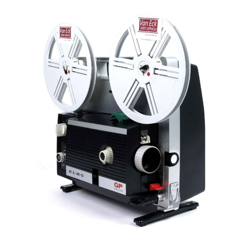
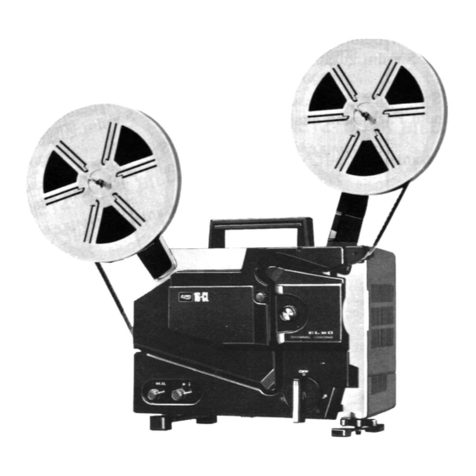
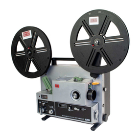
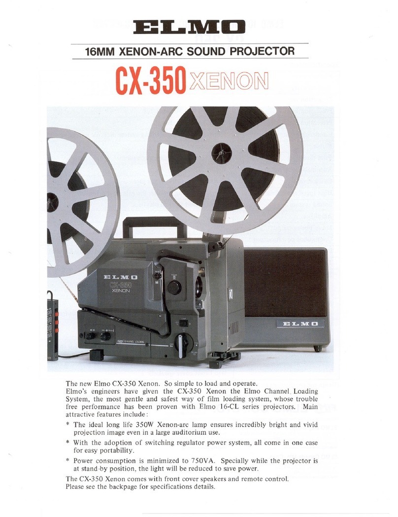
Elmo FILMATIC 16-A User manual

EL1'1ID
INSTRUCTION MANUAL

SPECIFICATIONS
Power supply
Projection lamp
Projection lens
Projection speed
Mo
toe
Reel capacity
Film threading
Loop restorer
Still projection
Reverse projection
Slow motion projectivn
Rewinding
Remote
contro
l
Sound system
Photo electric ce
ll
Amplifier circuit
Continuous power
output
(5%)
Tone
control
Microphone
Speaker
AC
Single phase,
50
/
60
Hz.
24V-250W quartz halogen
lamp with cold mirror.
F/1.3 50mm lens is standard.
F/i'.4
20mm lens, F/
1.
8
75mm lens, Conversion lens
(x0.8 & xI.25), Zoom
conve
rt
er
(xO.8
to
x
I.
25) and
Elmo scope lens are available
as accessories.
24 and 16 fps.
Induction motor.
Max. 600m
(2000ft).
Projector is
equi
pped with
360m (1200ft) reel.
Fully automatic.
Automatic.
Possible.
Possible.
Possible. 6
and
4 fps.
Flickerless system.
High speed rewinding.
Possible.(Depending on countries
.)
Magnetic and op
ti
cal re-
production.
Silicon photo-diode.
All I
C.
20W (8Q}.
Treble
and
bass separate
co
nt
rol.
Usabl
e.
2 built-in 12.5cm
(5")
dynamic speakers.

NAME
S OF PARTS
Q,
Fr
o
nt
reel
~
Fr
onl reel arm
Q) Folding bu
uo
n for
f
ront
reel arm
©
lli
gh speed rewinding knob
(§)S
elf
-threading lever
®
Fim
spr
oc
kel
<V
Pro
je
ction lens
@
Fo
cusing
knob
® A
cc
essory shoe
® Frami
ng
knob
@Oil inlet
@ Film trimmer
@ Speed change lever
® Elevation co
ntr
ol knob
~
Oi
l level
ga
uge
Q§i
Motor/la
mp
switch
Qj)
Exciter lamp hous
in
g
Q~
M-0 switch
Q$
Tone
co
ntrol
knobs
® Vo
lume
cont
rol
knob
® Amplifier switch
@ Lamp housing
@ S
elf
-threading release lever
@ Rear reel arm
@ Rear r
ee
l
® Folding
buu
on for
rear reel arm
@ H
andl
e
@ Still/Slow Motion lever
@
Mi
c./Phono rece
pt
a
cl
e
® Speaker cord rece
pt
ac
le
® Inclination adjus
te
r
Cl~
Power fuse holder
1!1
3>
l'
1>wer
cord receptacle
~-0
Covor for remote co
ntr
ol
roccpluc
lc
NAME OF PARTS
@,-
---
-Ill-
,
@·
-----
2
©
®
@
©
@
~
r.--+
-(6)
r
.-
---(j)
®
®
@
:======--
@
1----
- @
~---
@
- -
--0

CONDENSED OPERATING
INSTRUCTIONS
1P
la
ce the projector
and
speaker
in
posi-
tion. Connect the power c
ord
and
speaker cord.
5
Attach
the front
and
rear reels and
depress the self-t
hr
eading lever ([ ' until
it sits
in
positi
on
to set
the
s
elf
-threading
mechanism.
OFF
REV F
OR
W'D
~
LAMP LAMP
9
Turn
the motor/lamp switch ([6 to
"FO
R
W'
D"
and
then
to"
LAMP" .
OFF
___
.,.
REV. FORW"D
I
LAM
P
LA
MP
2 Leave
the
m
otor
/
lamp
switd1
I-
~
at
"OFF
"
and
th
e Still/Sl
ow
Mlltion lev
er
@
at
"NORMAL
".
6Insert the film leader.
aft
er
trimmi
ng.
into
the
threading sl
ot.
VOLUME
10
Switch o n the ampli
fi
er switd1 .
2.J
_ .
Then
turn the volume
con
trol kn
ub
~
and tone control knobs J9
lO
the
de
sired
pos
ition.

3
7
11
MAG.
OPT
Set
the
M-0
switch
()'~
to
"M"
when
using magnetic
sound
film
or
"O"
when
using
optical
sound
film. Leave
the
volume
contro
l
knob
@ at
"OFF".
[
After
about
50c
m
(20")
of film emerges
from
the
rear
end
of
the
projector,
lif
t
the
se
lf
-
th
read
in
g release lever
{~
;
to
st
op
lh
e
mo
tor.
Foc
us
th
e proj
ec
ted
image
uni
ii it
is sharp
by t
urn
ing the
fo<.:
using
knnh
(
~
;
and
turn
the frnming kn
ob
QQJ
to elimina
te
th
e frame lin
e,
if
necessary.
OFF
REV FORW'D
LAMP
LAMP
4
8
Turn
the
motor
/ l
am
p switch @
to
"LAMP
".
F
ocus
on
the
screen and r
e-
turn
it to
"OFF"
after
focusing.
Wind tht: rilm
on
the
rear reel
'2J
l .
12
For r
ew
inding.
turn
the
motor
/
lamp
switch(!§
to
"
REV"
and
pu
ll
th
e high
speed rewinding
knob
(! ; .
3

4
PREPARING
FOR
PROJECTION
Setting
up
the projector
I. Unlock the loc
ks
on
bo
th
sides
of
the front cover and remove
the
front
cover.
2. The
front
cover incorporates the speakers
so
it
can be used
as
a
speaker cabinet. Place the front cover beside the screen at a
height
of
Im
to
2m
(3ft
to
6ft). Remove the speaker cord from
the vinyl cover and connect it
to
the speaker cord receptacles at
the back
of
the projector ® and inside the front cover.
3. Set
up
the front and rear reel arms ® ® .
4. Remove the pow
er
cord from the vinyl cover. Connect
th
e
power
cord
to
its receptacle ® and plug it
into
the AC outlet.
5.
Make sure
that
the
motor
/lamp switch ® , volume control knob
VOtU
•l
BA
SS
TM&lC
® and tone control knobs @ are set
at
"OFF"
as illus
trat
ed
below.
Set the
M-0
switch @ to either "
MAG
."
wh
en using magne
ti
c
s
ound
film or " OPT." when using optical sound film.
•••
-
6. Make su
re
that
the
Still/Slow Motion lever @
is
set
at
"NORMAL".
7.
Attach
the
reel
of
film
and
the
empty
reel
on
the
front
reel arm
® and rear reel arm @ respectively, and lock
them
into
position by
turning
the reel locks.
8. Adjust sideway inclination
of
the
projector
by
turning
the
inclination adjuster ® on
the
rear leg.
9.
Turn
the
motor/lamp
switch @
to
"F
ORW'D"
and
then
to
"LAMP''.
If
the projected light is
not
centered
vertically on the screen, loosen the elevation
control
knob
QJ>
.
and
adjust height by raising
or
lowering
the
front
of
the
projector. Then
tighten the elevation co
ntrol
knob
and
tum
the
motor/lamp
switch back
to
"OFF".
10. Make sure
that
the projection speed change lever @
is
set
at
desired s
peed
;
"SOUND"
for
24 fps
or
"S
ILENT" for 16 fps.
lf
not
,
turn
the
motor
/
lamp
sw
itch
®
to
"FORW'D"
and
c
han
ge
ac-
cordingly.
Do
no
t c
han
ge the speed unless
the
motor
is runnin
g.
5

6
THREADING FILM
1.
Trim
the
film
end
with
the
film
trimmer
@
to
insure
smooth,
automatic
threading. Unless
the
film
end
is
properly
trimmed,
the
film
cannot
be threaded.
In case
the
film
leader is
bent
or
perforations
are damaged, replace
or
cut
off
the
leader.
2.
Depress
the
green self-threading lever ®
until
it
sits in
position
,
and
the threading mechanism
is
set
for self-
threading and
the
motor
starts running.
3.
Insert
the
film
end
into
the
threading
slot
marked
by a
red
arrow
until
the
film is pulled in.
4. When
about
SOcm
(20")
of
the
film emerges
from
the
rear
end
of
the
projector, lift
the
green self-threading
release lever @ ,
and
the
self-threading
mechanism is released and
the
motor
stops.
Wind
the
film
on
the
rear
reel. Film
threading
is
now
completed.

PROJECTION
R
Projec
tion
is
started
by turning the
motor
/lamp switch ®
to
"FO
RW
'D" and then
to
"LAMP
".
(Un
less the
self-threading mechanism
is
released, the
motor
/
lamp switch
cannot
be turned.)
When the projected
image
appears
on the
screen
,
check
the following
points:
1. Focus
Tum
th
e focusing
knob
@
to
bring the image
into focus.
2. Framing
If the frame line appears
on
the screen,
turn
the framing
knob
®
to
eliminate it.
3. Volume
and
tohe
Switch
on
the
amp
lifier switch @ .
Then adju
st
volume and tone by turning the
volume co
ntrol
knob
® and t
one
co
ntrol
knobs ® respectively.
7

VARIOUS PROJECTION
1.
Slow motion projection
2.
Still projection
For slow motion
pr
o
je
c
tion
, move the still/
slow motion lever ® from "NORMAL"
to
"S
LOW
",
and~
the projection speed is slowed
"
down
to
a quarter
of
the normal speed.
Still projection during operation can be done
by moving the still/slow motion lever ®
to
"SLOW" and then further
to
"STILL
" while
depress
in
g the lever
at
the
po
sition
of
"SLOW"
and holding it.
3. Reverse projection
r
-------oFF
When the
motor
/lainp switch ®
is
turned
to
8
REV
.
~w
·
o
LAMP~MP
"
REV"
, the film moves in reverse. When
it
is
turned
furt
her
to
"LAMP"
, the film is projected
in reverse.
4. Remote control projection
Note:
For
ce
rtain countries, t
he
ptojeclor is
delivered without the r
emot
e
oo
ntrol
receptacle, and in
th.is
case, this in-
struction is
not
applicable.
Remote
contro
l projection can be
do
ne by
connecting an optional remote control de
vi
ce
to
th
e r
emo
te control receptacle insi
de
its
cover @ . Be su
re
to
opera
te
a remote co
ntr
ol
switch by setting the m
otor/
lamp
sw
it
ch ®
to "
FO
RW
'D
".
(Do not
tum
it to "LAMP".)
The wiring
fo
r rem
ot
e control is illu
st
r
ate
d
belo
w.
:~:
5
~
6
Remote
con
tr
ol
r
ecep
t
ac
le

UNLOADING FILM MANUALLY
When removing
th
e film manually
from
the
film path:
I. Push down
the
button
® shown in the picture
to
open
the
sprocket shoe.
2.
Swing
open
the hinged lens holder toward
yo
u.
3.
Op
en
the
cov
er
® and push down the sprocket sh
oe
©
as
illustrated in the p
ictu
re.
4. Now the film can easily be taken
out
manually.
IMPORTANT
Do
not
move
the
projector when
the
lamp
is
on
or
before
the
lamp
is
adequately
cool as this maydamage
the
lamp.
9

10
WHEN PROJECTION IS COMPLETED
When the film has been projected, first
tum
off the
Lamp
by turning
the
motor/Lamp switch @
to
"FORW'D",
and
then
turn the volume
control
knob
®
to
"OFF"
and switch
off
the amplifier switch ® .
Af
ter
the
film has been wound
con;IJ~letely
on
the rear reel, move the
still/sl
ow
motion
lever @ to
"STILL'\
and leave the
motor
running
to
ensure
that
the lamp is adequately cooled.
Rewinding the fi
lm:
I.
Insert the film
end
into
the slot
of
the
front
reel hub.
2.
Turn the
motor/
lamp switch @ to
"REV".
3. Pull the
high
speed rewinding
knob
© toward you, and the
film
is rewound
at
high
speed. (The
high
speed rewinding
knob
is
released automatically when the projector operates for forward
projection. So
you
may leave
it
in
this position until the
next
projection.)
4.
After
making sure
that
the lamp is adequately cool, turn the
motor/
lamp switch @
to
"OFF''.

STORING
1.
Disco
nn
ect
the power
cor
d first. Return
the
take-up reel, p
owe
r
coi
d
and
s
peaker
cord
to
their
storing places. Handle
the
co
rd
s
with care so as
not
to
damage
them
.
2.
L
ower
the
front
and rear reel arms by depressing
the
folding
but
to
ns @
and
®
at
the
base
of
the
reel arms.
3. L
oosen
the
elevation
control
knob
~
,
return
the
eleva
tion
leg
to its
retracted
position,
and
retighten
the
knob. Never
transport
the
projector
with
the
elevation leg
extended.
4. Replace the
front
cover
on
the
projector
and
put
on
the vinyl
cover.
11

12
CLEANING
Open the hinged lens holder l
owar
d
you
to
clean the film gate
and
lens
surfaces.
1.
Fi
lm
gate
The film gate, which is in
co
n
ti
nu
ous
con
tact
with the film, is
precisely machined
to
prevent damage
to
the
film. When dust
or
ot
her
malter
adheres
to
the
gate
,
il
may scr
atc
h or damage
the
film.
From
time
to time,
therefore
, especially
after
heavy use,
t
he
fi
lm gate
and
su
rroun
ding area sh
ou
ld be cleaned with
th
e
sma
ll
brush provided
or
a soft cloth. Never
attempt
to
clean
the
film gate with
anything
made of
met
al or touch the film se
nd
ing
claw during cleaning.
2.
Pr
oj
ection lens
Remove
the
lens
by
pulling straight out. Clean
both
the
front
and rear surfaces gently with a
soft
hair brush or
soft
cloth.
Never blow on the lens surfaces
or
touch with bare fingers.
CHANGING FREQUENCY (CYCLE)
When changing frequency from
50
Hz
to
60
Hz a
nd
vi
ce versa, d
is-
conn
ect
th
e
power
cord first, remove
the
back cover
and
th
en s
hift
the
frequency changing belt as shown in the picture.

MAINTENANCE
Be
sure
to
di
sconnect
the power co
rd
before replacing the lamps and
fuses.
Wh
en replacing the projection lamp,
mak
e sure
tha
t
it
has cooled
sufficiently
to
handle.
Pr
oj
ec
ti
on lamp
(1) Replac
in
gthe projection la
mp
:
1. Open the l
amp
housing
@.
2. Loosen
the
screw ®
and
turn
the
lock-
ing lever @ to
re
lease
the
mirror holder
© .
3.
PuU
the
mirror holder © toward
you
and
pu
ll
the
l
amp
straight our.
4.
When in
sert
ing a new lamp, leave
the
paper sleeve or cardboard cover
on
the
lamp. Never
touch
the glass p
ortion
of
the l
amp
and
mirror directly
with
bare
fingers.
5. Align
th
e two pins
of
the lamp with
the
holes in
the
socket
@
and
push the
lamp
into
the
socket
as far as
it
will go.
6.
Pu
sh the mirror holder © back
to
its
place and fix it.
(
2)
Adj
us
ting the
po
sition of t
he
projection lamp:
If
the
projected image is
too
dark
or uneven
after
replacing
the
lamp, adjust
the
lamp
posi-
tion
by
turning the adjusting screws ® , ®
and © .
I.
To
adjust brightness on
the
upper
or
lower side
of
the image, turn
the
adjust-
ing screw ® .
2. To adjust brightness
on
the
right
or
left
side
of
the image, turn
the
adjusting
screw ® .
4.
After
adjus
tment
with the adjusting
screws ©
and
® , make fine adjust-
ment
by
turning
the adjusting screw © ·:
13

Exciter lamp
Power fuse
Amplifier
fuse
14
The
quality
of
optical
so
und
reprod
uction
will
d
eteriorate
if the
exciter
l
amp
is used for a
long
time
.
To replace the exciter lamp:
L.
Remove
the
exciter lamp housing @ by
pulling
fro
II\.
underneath
toward
you.
2.
Pull o
ut
the
metal shielding cylinder @ ,
pu
sh
up
th
e ejec
tor
@
and
turn
the
lamp counterclockwise
to
remove it.
3.
To
install a new lamp, align
the
three
guide pins
with
the
holes
of
the
l
amp
base flange, wjth
the
notch
of
the
lamp
base flange facing d
ow
nward.
Then
push
the
lamp a
nd
tum
it clockwise as far as
it
will go.
4. Push down
the
ejec
tor
to
fix
the
l
amp
in
position
and
attach
the
shielding cylinder
with
its
open
side facing upward.
When replacing
the
power fuse (SA),
turn
the
power
fuse
hold
er ® counterclo
ckw
ise, and
the
fuse can
be taken
out.
I.
Pull out
th
e volume
and
tone
co
nt
rol
knobs
@ ® .
2.
Remove
the
back cover.
3. Remove the chassis r
eta
inin
g scr
ew
® of
the
amplifi
er
and
pull
out
the amplifier
unit.
4.
There
are
two
fuses;
th
e right one
(2A)is
for
the
excite
r lamp
and
the
other(3A)
is for
th
e amplifier.

LUBRICATION
OIL
LEVEL
®
Oiling
for
intermittent
feeding mechanism
The
intermittent
feeding mechanism is lubricat-
ed
by
the
oil circulation system.
The
oil level
should be
kept
between the two lines
on
the
oi
l level gauge @ .
If
the
oil is insufficient
after
freql)ent use, add exclusive
Elmo
Special
Oil through the oil inlet ® while observing
the oil level gauge,
until
the oil level is close to
the upper limit
on
the
oil level gauge.
Changing oil
It
is recommended to change
the
oil
after
a few years
of
use,
though
it depends
on
the
frequency
of
using
the
projector.
To change the oil:
1.
Remove
the
oil
inlet screw
and
the
screws
2.
® and @
of
the oil
tank
housing
shown in
the
picture, and
the
oil
tank
housing can be detached.
Place a suitable receptacle beneath the oil
outlet
on
the lower, right side
of
the
oil
tank.
3.
Remove
the
oil
outl
et
screw
and
drain
the oil.
4. Operate
the
projector and drain a
ll
the
oil
in
the
oil feed pipe. Never operate
the projector over
one
minute
after
the
oi
l has been fully drained.
S.
Tighten the oil
outlet
screw.
6.
Pour Elino Special Oil into
th
e oil inlet
while observing
the
oil level gauge.
Oiling
for
bearings
All the bearings are ball bearings or special
oilless types. Although frequent oiling
of
the
bearings is
not
necessary,
it
is
recomme
nd
ed
to
apply
one
or
two
drops
of
oil
to
the
rotating
parts
other
than
the ball bearings
packed with grease, after
about
a
year
of
use.
lk
sure
to
disconnect the power cord before
removing
the
back cover. Never
put
the
oil
on
the
rubber
roll
ers
and belts.
15

16
TROUBLE SHOOTING
1.
Film will not thread
o when the film end is bent
as
shown in Fig.
1.
o when perforations are damaged
as
shown
in
Fig. 2.
o when the film
end
is jagged as
shown
in
flg.
3.
o when the film end is twisted"or curved as shown
in
Fig.
4.
o when the film
end
is extremely curled as shown in Fig. 5.
o when the film end is reversely curled as shown in Fig. 6.
bU
11
[
-
..
Fig
. 1 Fig. 2
AIll l
)l
l 1l II
Fig
. 3
Fig.
4
Fig
. 5
Fig.
6
Properly
tr
immed film
end
(I
l l l l l Trim the film
end
with the film
trimmer @ . Straighten the film
leader if
it
is extremely curled
or
replace the film leader
if
it
is reversely
curled.

2. Motor w
ill
n
ot
run
o when the power cord is
not
properly plugged in.
o when the power fuse is broken.
.3. Self-
thr
eading will
not
be
don
e
o when the threading lever is
not
depressed.
o when the
motor
/lamp switch
is
not
positioned
at
"OFF".
o when the sprocket shoes are open.
o when the film gate
is
open.
o when the film
end
is
not
properly trimmed.
4. Projection lamp will
not
light
o when the l
amp
is broken.
5. Sound wi
ll
not
be
reproduced
o when the M-0 switch is
not
properly positioned.
o when the exciter lamp
or
its fuse
is
broken (in case
of
optical
reproduction).
o when the
amp
lifier is n
ot
switched on.
o when the volume is turned down to the lowest limit.
o when the amplifi
er
fuse is broken.
o when the speaker cord is
not
properly connected.
o when sound
is
not
recorded
on
the film.
6.
Sound
will be
out
of
tune
o when the speed change lever is positioned
at
"S
ILENT''.
1.
Automatic
loop res
tor
er will work irregularly
o when the proper film len
gt
h between the
two sprockets
is
lost because the perforations
of
a few fram
es
are damaged. In this case,
stop
the projector, open
either
sprocket
sh
oe
,
and
reset the film loop.
17

18
ACCESSORIES
Translucent screen
60crn x 80crn
(23.
6"
x
31.5")
39crn x 52crn
(15.4"
x 20.
5")
Elmo Scope Lens
This lens is used for projecting Cinemascope
mo
vi
es.
lt
can be
put
in
front
of
the projection
lens simply
by
mounting
it
on the accessory
sh
oe
of
the projector. The projected image is
horizontally magnified twice.
Conversion
Lens
This a
tt
achment lens converts the foc
al
length
of
the projection lens
to
either
x0
.8
or
x
l.
25,
i.e., the
st
a
nda
rd
50mm
lens plus this accessory
serves asa 40mm wide-angle lens
or
by reversing
it a 63mm teleph
oto
lens. You can make use
of
it
when the projected image
is
too
small or
large.
Daylight Rear Projection Device
This accessory prism, which can
be
put
.on
th
e
accessory shoe
of
the projector, provides a
clear projection image in a bright place when
used with a special translucent screen.
Table of contents
Other Elmo Projector manuals

Elmo
Elmo Boxi MP-350 User manual

Elmo
Elmo HP-L2900H DX User manual

Elmo
Elmo ST-600D User manual

Elmo
Elmo EDP-S10 User manual

Elmo
Elmo HP-400HZ User manual

Elmo
Elmo 16-CL Optical User manual

Elmo
Elmo Boxi MP-350 User manual

Elmo
Elmo EL55R2 User manual

Elmo
Elmo LCD Data Protector EDP-X80A4 User manual

Elmo
Elmo CRP-221 User manual