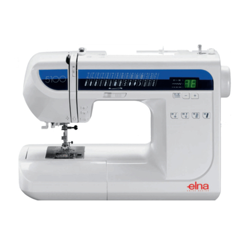
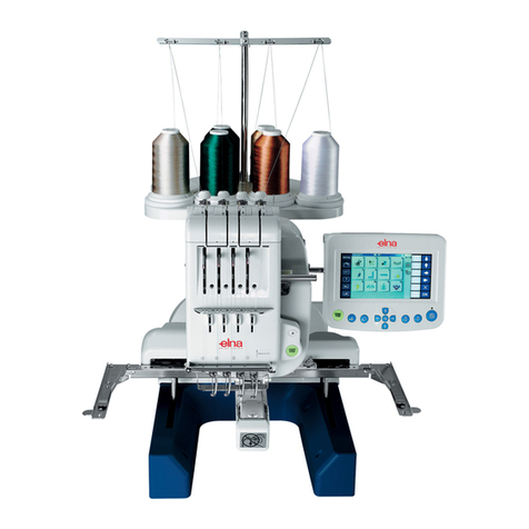
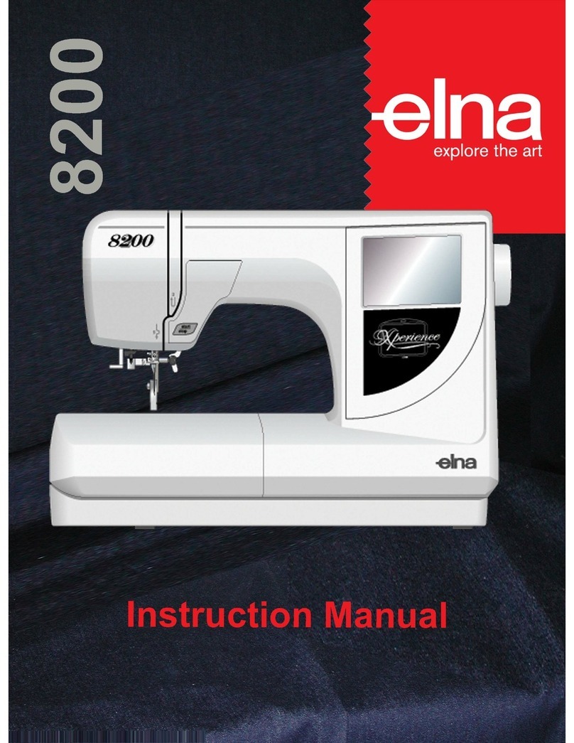
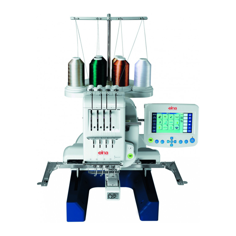
ELNA xquisit User manual

SERVICE MANUAL
08/02 Printed in Switzerland 395 902 – 82

Elna International Corps. SA Xquist service manual
Feed mechanism
1. Feed amount 0 to 5 mm (in increments of 0.1 mm in the range from 0.2 to 1.0 mm, and
1.5 mm, 2.0 mm, 2.3 mm, 2.5 mm, 3.0 mm, 3.5 mm, 4 mm, 4.5 and
5.0mm)
2. Reverse stitching length 0 to 2.5 mm (for straight stitch) Fixed at 0.5 mm (for the other patterns)
3. Feed amount adjustment By the manual switch mounted on the LCD
Feed amount (pitch) is given on the LCD.
4. Reverse stitching The machine performs reverse stitching at low speed (11 rpm) while the
reverse stitching switch is ON.
5. Lateral feed Fixed at 2 mm when a lateral feed pattern is specified.
6. Descending of feed dog Automatically comes down when the embroidering device is set on the
machine.
Special-purpose mechanism
1. Automatic thread tension controller
By the thread-feeding stepping motor Manual switch for increasing/decreasing the amount of needle
thread of the automatic thread tension controller by a material thickness sensor (to
increase/decrease the amount of thread in 8 steps).
2. Automatic thread trimmer
Lateral STM is actuated by pressing the thread-trimming switch so as to bring the thread trimming
mechanism in the standby state. Then the hook driving shaft turns one and a half times (when the
machine has sloped with its needle down) or two times (when the machine has stopped with its
needle up) by the sewing machine drive motor and the main shaft is disengaged at the first turn. The
machine actuates the thread trimming knife to cut the thread (115 rpm) and stops with its needle up.
Disengagement of the main shaft is released before stop.
3. Automatic backtack sewing
By pressing la key after selecting the pattern, backtack sewing is performed at beginning and end of
sewing, and the needle and bobbin threads are cut finally.
4. Helpful pictograph
Operation lever, bobbin winder, buttonholing set, running out of needle thread, pattern selection
display, inoperative key display, limit of pattern memory display, pattern in storing, calling display
(when the embroidering device is set), needle raising indication, embroidery frame installing
indication, embroidery frame changing indication, embroidery card inserting indication, difference of
embroidery carc indication, pattern clearing indication, and bobbin thread remaining amount
indication.
5. Automatic needle threading mechanism
When setting thread to the thread retaining section of the thread transfer body, threading from the
section to needle is automatically performed by pressing the key of the operation panel.
6. Automatic buttonholing
Auto return type fully automatic buttonholing.
Buttonhole size detection, automatic stop after backtracking at the sewing end (backtracked (L and
S) keyhole), and purl stitching using super buttonholing button is possible. Buttonholing plate is
provided.
7. Bobbin thread remaining amount.
Bobbin thread remaining amount is detected by the LED sensor when the bobbin thread is running
out, and the message is shown on the LCD. Then the sewing machine stops.
Elna International Corps. SA Xquist service manual
8. Limit sensor.
In order to prevent the bobbin from being excessively wound when automatically winding bobbin, the
sensor monitors during bobbin winding and detects that the bobbin is wound more than the specified
amount. Then bobbin winding automatically stops.
9. Pattern selection.
Direct selection of Patterns through a transparent touch panel and indication of selected pattern on
LCD.
10. Number of patterns
Practical patterns 87, Continuous patterns 58, Adherence one point 34, One point 167, Lettering
characters 4 fonts 450, large pattern 44.
11. Constant-position needle bar stopper.
The machine stops with its needle up or down using the synchronizer shield plate and detector
(photo-interrupter) mounted on the main shaft.
When the thread trimming presser is raised, when the embroidering device is used or when the
bobbin is to be wound, the machine stops with its needle up. In a case other than those described
above, the machine stops with its needle down.
12. Prevention of wrong-setting of needle.
It is designed so as not to insert the needle in the wrong direction.
13. Operation guide.
How to operate the sewing machine, advice and how to sew are indicated on LCD.
14. Prevention of overheat of motor.
If the sewing machine motor shaft is locked, the power supplied to the motor is automatically turned
OFF after 1 to 1.5 seconds.
If the motor becomes extraordinarily hot in such cases as the sewing machine continuously runs at
high speed, the thermal sensor built in the motor detects and stops the machine operation. (The
power is turned ON again after the motor has cooled down.)
15. Automatic bobbin winder.
When performing the embroidering, exclusive bobbin thread can be wound to bobbin without
removing bobbin. In addition, after bobbin winding, threading to bobbin thread tension spring and
thread cutting are performed. Then sewing can continue.
Microcomputer and ROM
32-bit microcomputer 1
Gate array 1
ROM 32MB
Flash ROM 8MB
Embroidering card Available from 4MB to 64MB (Smart media)
Gate array
A large scale and original circuit is necessary for the computer sewing machine. The circuit is built in
the IC, which is the exclusive one produced for this model only.

Elna International Corps. SA Xquist service manual
Outer dimensions and weight
Main unit 47.9 cm (width) X 32.4 cm (height) X 21.5 cm (depth) Weight12.4 kg
Main unit with case 49.5 cm (width) X 33.0 cm (height) X 23.5 cm (depth) Weight13.7 kg
Embroidering device 33.5 cm (width) X 13.0 cm (height) X 32.0 cm (depth) Weight2.3 kg.
Power consumption
Sewing machine main unit. 120V 60 Hz
(Lamp only) 13.5V 3 W
Technical explanation
Sewing speed
Max. sewing speed in high speed operation.
For straight stitching 850 ± 50 rpm
For embroidering (at high speed) 800 ± 50 rpm
Low sewing speed in high speed operation
For bobbin winding 600 ± 15 rpm
Max. sewing speed in medium-high speed operation.
For zigzag pattern 700 ± 50 rpm
When bartacking buttonholes on both sides 525 ± 15 rpm
Max. sewing speed in medium speed operation
For embroidering (at medium speed) 410 ± 10 rpm
Low sewing speed in medium speed operation
For key hole buttonholes, lateral feed patterns, 300 ± 10 rpm
High sewing speed in low speed operation
For embroidering (at low speed) 245 ± 10 rpm
Low sewing speed In low speed operation 115 ± 10 rpm
Extra low speed operation 70 ± 10 rpm
In case of embroidering, the sewing speed automatically changes over according to travel amount of
X-feed and Y-feed of embroidery STMs regardless of the slide controller. (800, 750, 41 0 and 245
rpm) Max. sewing speed (800 rpm) is limited according to the position of slide variable resistor.

Elna International Corps. SA Xquist service manual
INDEX BY TROUBLES (MECANICAL TROUBLES)
Phenomenon Item to be checked
Defective thread
tension P-17 Height of the presser foot P-20 Height of the feed dog
P-20 Inner hock detent P-21 Tension release plate and base tension
P-26 Bobbin thread tension P-40 Adjusting the actual feed amount
P-43 Adjusting the material thickness
Stitch skipping P-17 Position of the presser foot P-18 Height of the needle bar
P-18 Needle to hook timing P-19 Clearance between the needle and hook
Thread
breakage P-18 Height of the needle bar P-18 Needle to hook timing
P-20 Inner hook detent plate
Hitched stitch P-17 Needle entry
Defective feed
of the material
P-17 Height of the presser bar P-20 Height of the feed dog
Contact of the
needle P-17 Needle entry P-19 Clearance between the needle and hook
P-26 Timing belt
Pattern shape P-27 Disengaging the main shaft P-27 Main shaft disengaging stopper
P-42 Longitudinal feed and lateral feed
Automatic
thread trimmer P-21 Base tension P- Disengaging the knife P-24 Lateral position of the thread trimmer cam
P-24 Moving knife guide (upper) P-25 Moving knife guide (lower)
P-25 Height of the looper P-26 Bobbin thread tension
P-26 Timing belt
Noise P-26 Timing belt P-28 Motor belt
Buttonhole P-27 Buttonhole
Bobbin winder P-32 Automatic bobbin winging device
Needle threader P-28 Needle threader
Embroidering
device P-37 Replacing procedure of the motor P-38 Adjusting the belt
P-38 Adjusting the origin
AUTOMATIC NEEDLE THREADING (TROUBLE AND CORRECTIVE MEASURE)
Trouble Cause Corrective measure
Needle thread comes
off the thread
retaining section
when the transfer
body rotates and
comes down.
1. The set needle thread does not enter
up to the root of shaft and is narrowly
retained at the top end.
Adjust the retaining pressure at
the upper position (see page 30).
2. The retaining pressure does not
become high. Turn OFF the power,
and turn the driving shaft
counterclockwise. The retaining
pressure changeover plate woks and
the spring is compressed to increase
the retaining pressure
When the is not compressed,
check the adjustment of the
retaining pressure change-over
link (see page 30).

Elna International Corps. SA Xquist service manual
1. Height of the threading hook is improper. Check the adjustment of the needle threader
(see page 29)
2. Thread tensed in front of needle is not in the center
of needle eyelet at the lower position of the transfer
body.
Check the vertical adjustment of the lower
position (see page 30).
3. Longitudinal position of the transfer body in terms
of needle is not proper at the lower position of the
transfer body
Check the longitudinal adjustment of the
lower position (see page 30).
4. Thread retaining section is open at
the lower position of the transfer
body.
Check the adjustment of the retaining
pressure change-over link (see page 30).
Thread fails to pass
the needle eyelet.
5. The base tension is open when threading Check the adjustment of the base tension
(see page 8).
1. The base tension is open when threading Check the adjustment of the base tension
(see page 8).
2. The position of needle clamp threading arm is too
high. Check the height of needle clamp threading
arm (see page 30)
3. The transfer body is attached to the left side. Check the lateral adjustment of the transfer
body (see page 30).
Thread is not caught
by the needle clamp
thread guide.
Needle thread fails to
enter the fork end.
4. Longitudinal position of the transfer
body is improper. Front and rear. Check the longitudinal adjustment of the
lower position (see page 30).
1. The transfer body is attached to the left side. Check the lateral adjustment of the transfer
body (see page 30).
2. The position of needle clamp threading arm is too
high. Check the adjustment of the height of needle
clamp threading (see page 30).
The needle clamp
thread guide fails to
catch thread.
Thread deflects to the
inside of the thread
guide and cannot be
caught.
3. The thread path control plate is attached to the left
side. Adjust the thread path control plate (see
page 30).
1. The transfer body is attached to the right side. Check the lateral adjustment of the transfer
body (see page 30).
2. The position of needle clamp threading arm is too
low. Check the adjustment of the height of needle
clamp threading arm (see page 30).
The needle clamp
thread guide fails to
catch thread.
Thread deflects to the
outside of the thread
guide and cannot be
caught.
3. The thread path control plate is attached to the right
side. Adjust the thread path control plate (see
page 30).
1. Malfunction of the threading body Installing position of the face plate is
improper
The face plate inside cover is moved to the
right.
(The face plate installing plate is slanting
attached.)
Defective change-over of STM
2. Malfunction of the base tension Check the motion of the base tension
3. Malfunction of the mis-threading preventing plate Check the motion of the mis-threading
preventing plate.
Defective threading
to the thread take-up
spring and thread
take-up lever.
4. Rising amount of the auxiliary roller cover

Elna International Corps. SA Xquist service manual
Automatic bobbin winding ( troubles and corrective measure).
Bobbin thread winding from the exclusive bobbin thread
Trouble Cause Corrective measures
1. The hook cover is not attached. Attach the hook cover.
2. Threading to the thread retaining
plate is not correct. Check whether threading to the thread retaining
plate is as shown i the threading diagram.
Check whether threading is made to the lower
side of thread retaining plate hook.
3. Retaining force of the thread
retaining spring is too low. Adjust the height of thread retaining plate A
(see page 30).
4. After starting thread winding, the
thread which has come out of the
b
obbin slit passes the upper side of
“U” letter at the top of thread
retaining plate A and comes off
the thread retaining spring.
Check the position of thread retaining plate A
hook.
Thread fails to be
wound in bobbin.
5. Bobbin fails to rotate. Malfunction of the gear connecting link.
Deformation of the gear connecting link plate
spring.
1. There is a scratch on the inner
hook and thread is caught with it. Correct the inner hook.
2. Thread is caught with the inner
hook détente plate and runs
around.
Correct or replace the inner hook detent plate.
Adjust the inner hook detent plate (longitudinal
direction see page 6). If it is excessively moved
to the forward direction, thread is caught it.
3. Thread has not completed and the
bobbin thread is removed by the
needle thread.
Same as 1 and 2 above.
The hook cover pile is excessively tilted.
Thread is not
cough by the
inner hook thread
guide.
4. Threading has completed, but the
thread cannot be drawn out since
thread end is drawn in and comes
out from the entrance side.
Same as 1 and 2 above.
The feed bar pile fails to retain thread.
1. There is a scratch on the inner
hook and thread is caught with it. Correct the inner hook.
2. Thread is caught with the inner
hook detent plate and runs around. Correct or replace the inner hook detent plate.
Adjust the inner hook detent plate (longitudinal
direction see page 6). If it is excessively moved
to the forward direction, thread is caught it.
3. The outer hook fixed knife is dull. Replace the outer hook fixed knife.
4. The bobbin thread tension is too
low. Adjust the bobbin thread tension (see page 17).
Bobbin thread
fails to cut.
5. Tension on the side of spool for
exclusive thread is too low. Check the thread winding tension plate or
bobbin thread guide.
1. Thread slackens when pushing the
thread with the hook of outer hook. The position of gear connecting link stopper s
improper and the bobbin driving gear is
disengaged.
Bobbin rises and the gear is disengaged.
2. A scratch on the hook of outer
hook. Check the inclined plane of the hook of outer
hook.
Thread is not
retained to thread
retaining plate A
after completing
thread winding.
3. Tension of thread retaining plate A
is too high. Check the retaining force 65 to 90g of thread
retaining plate A (asm.) only.

Elna International Corps. SA Xquist service manual
Dismantling of plastic frames
UNDER COVER
1. Loose the two screws 1 and 2.
2. Remove the under cover
FACE PLATE COVER
1. Loose the screws 1 and 2
2. Remove the claw section A and B using a thin
screwdriver or the like
BELT COVER
1. Remove the two screws 1
2. Insert a thin screwdriver into the hooking
section C and push in the direction of arrow
mark to remove the belt cover

Elna International Corps. SA Xquist service manual
FREE ARM BOTTOM COVER
1. Loose the screws 1 and 2.
2. Remove the bottom cover
BOTTOM PLATE (BASE)
To facilitate the disassembling of the front and
rear panel, please loose the 5 screws from the
base.
1. Loose the screws 1 through 5.
2. Remove the base
FRONT PANEL
1. Remove screws 1 and remove the needle plate
2. Remove the screw 2 and loose the screw 3
3. Insert a thin screwdriver into section C and
remove the claw.
4. Applying force to section A in the direction ->
inserts a thin screwdriver into section D and
removes the claw.
5. Remove section E at the jaw section while
lowering the rear panel.
6. Make sure that the small pin F inside of the
front panel in G is lowered before open the
claw H.
7. Remove all connectors see drawing below.

Elna International Corps. SA Xquist service manual
FRONT PANEL CONNECTION
1. Remove the connectors 4, 5, and 6 connected
from the front panel to the microcomputer
circuit board.
2. Then draw out the flexible card connector 7
after the lock of connector 6 has been
released.
3. Remove connector 8 connected to the inverter
circuit board.
To remove the Rear panel.
1. Remove the Under cover.
2. Remove the Belt cover.
3. Remove the Free arm bottom cover.
4. Loose the 5 screws from the bottom plate
base.
5. Disconnect all Front panel connectors.
REAR PANEL
1. Loose the screw 1.
2. Remove the screw 2, situation of this screw.
Turn the hand wheel so that the needle bar is
in lowest positioning (this screw fixe the rear
cover and is to reach from the front inside over
the take up lever).

Elna International Corps. SA Xquist service manual
REAR PANEL
1. Remove the screws 3 and 4.
2. Lower presser-lifting lever 5.
3. Lift handle 6, draw section 7 and remove the
rear panel.
4. Remove claw section 8 from the bottom plate.
EMBROIDERY UNIT
FRAME OF EMBROIDERY DEVICE
1. Remove the screws 1 through 7.
2. Press a and pull

Elna International Corps. SA Xquist service manual
UPPER MAIN SHAFT DISENGAGING
Location of components to be adjusted.
6. Remove the Under cover.
7. Remove the Face cover inside.
8. Remove the Belt cover.
9. Remove the Free arm bottom cover.
10. Loose the 5 screws from the bottom plate base.
11. Remove the Front panel.
12. Disconnect all Front panel connectors.
13. Disconnect all connectors on the left side from the
microcomputer circuit board so that you have
access to the Disengaging mechanical system.
HOW TO ADJUST
Relation of the position of the main shaft disengaging
cam and the main shaft-disengaging cam.
1. Provide a clearance of 1,6 mm between the main
shaft hand wheel and the main shaft-disengaging
cam. Using a 1.6-mm spacer or the like.
2. Loosen adjustment screw 1 and the tree screws 2
from the needle throwing STM installing plate.
3. Move needle-throwing STM installing plate 3 to the
left or right to adjust the distance of 2 mm between
the main shaft-disengaging cam 4 and main shaft
disengaging link 5.
4. Tighten the tree screws 2 to fixe the needle
throwing STM installing plate.
Note:
When this adjustment is performed, the needle entry
point shifts. Perform again the needle entry
adjustment.
After this adjustment, perform the Main shaft
disengaging stopper adjustment.
MAIN SHAFT DISENGAGING STOPPER
1. Provide a clearance of 1,6 mm between the main
shaft hand wheel and the main shaft-disengaging
cam.
2. Loose the screw 1.
3. Make the top end of the main shaft disengaging
stopper comes in contact with the stopper spring.
4. Tighten the screw 1.
5. After adjustment, apply grease to the sections
below.
•Joint of the main shaft-disengaging cam and
the main shaft hand wheel.
•
Cam section of the main shaft disengaging

Elna International Corps. SA Xquist service manual
cam.
•Top end section of the main shaft disengaging
stopper.
MAIN MOTOR
MAIN MOTOR.
1. Remove the Under Cover.
2. Remove the Belt Cover.
3. Remove the Free arm bottom cover.
4. Loosen the 5 screws from the bottom plate
base.
5. Remove the Rear Cover (see below).
MAIN MOTOR.
1. Remove the screw 1 situation of this screw.
Turn the hand wheel so that the needle bar is in
lowest position (this screw fixe the rear cover
and is to reach from the front inside over the
take up lever).
MAIN MOTOR.
1. Remove the two screws 1
2. Remove the two screws 3
3. Remove the screw 4.
4. Lower the presser bar 5.
5. Lift the handle 6, draw section 7 and remove
the rear panel.
6. Remove claw section 8 with the under cover.

Elna International Corps. SA Xquist service manual
MAIN MOTOR.
1. Remove the two screws 1.
2. Disconnect the motor.
3. Remove the motor belt.
MAIN MOTOR
How to adjust the motor belt.
Adjust the motor belt tension by moving the motor
up or down and after the adjustment, fix the belt
screws.
Fuses
F2 = 5 A (Motor)
F3 = 3,15 A
F4 = 3,15 A

Elna International Corps. SA Xquist service manual
AUTOMATIC BOBBIN WINDING
Location of components to be adjusted.
1. Remove the under cover.
2. Remove the face cover inside.
3. Remove the belt cover.
4. Remove the free arm bottom cover.
5. Remove the front panel.
1. Adjusting the inclination and the longitudinal position of thread retaining plate A, temporarily
determine the height and fix it.
2. Turn the bobbin thread intermediate gear by hand to move thread retaining plate A in the
state that the throat plate and the hook cover are attached.
3. Then temporarily determine the height of thread retaining plate A so that it can move from
the forward end position (above the inner hook) to the backward end position.
4. Insert a hexagon wrench key from the frame hole and loosen the thread retaining plate C
set screw to adjust the height.

Elna International Corps. SA Xquist service manual
Adjust the height so that the clearance
provided between the upper plane (rib which
is higher) of the bobbin rib and the bottom
end of thread retaining plate A is 0 to 0.3
mm at the forward end position.
This manual suits for next models
1
Table of contents
Other ELNA Sewing Machine manuals

ELNA
ELNA 664 - User manual

ELNA
ELNA 6200 - User manual

ELNA
ELNA 664PRO - User manual

ELNA
ELNA 2600 User manual

ELNA
ELNA Creative Series User manual

ELNA
ELNA eXpressive 900 Technical manual

ELNA
ELNA eXpressive 970 User manual

ELNA
ELNA 6200 - User manual

ELNA
ELNA eXplore 120 User manual

ELNA
ELNA 8300 - LEAFLET User manual