ELNA eXperience 520 User manual

SERVICE MANUAL
MODEL: eXperience 520

TABLE OF CONTENTS
WHAT TO DO WHEN........................................................................................................ 1-3
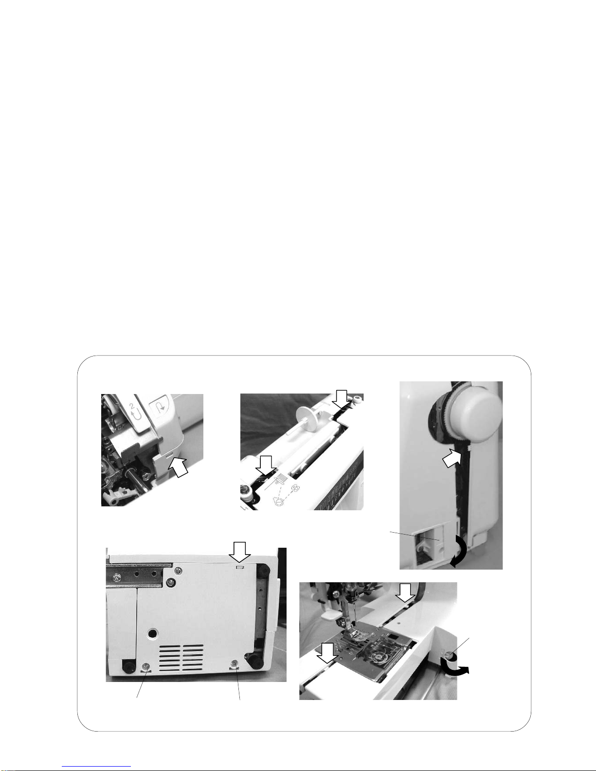
SERVICE ACCESS (1) FACE COVER............................................................................... 4
SERVICE ACCESS (2) BED COVER ................................................................................. 5
SERVICE ACCESS (3)(4) FRONT COVER .................................................................... 6-7
SERVICE ACCESS (5) REAR COVER............................................................................... 8
MECHANICAL ADJUSTMENT
PRESSER BAR HEIGHT AND ALIGNMENT .............................................................................. 9
NEEDLE DROP POSITION ....................................................................................................... 10
NEEDLE TO SHUTTLE TIMING................................................................................................ 11
NEEDLE BAR HEIGHT.............................................................................................................. 12
NEEDLE CLEARANCE TO SHUTTLE ...................................................................................... 13
BACKLASH (BETWEEN LOWER SHAFT GEAR AND SHUTTLE HOOK GEAR).................... 14
FEED DOG HEIGHT.................................................................................................................. 15
ZIGZAG SYNCHRONIZATION.................................................................................................. 16
NEEDLE THREAD TENSION.................................................................................................... 17
STRETCH STITCH FEED BALANCE........................................................................................ 18
REPLACEMENT AND ADJUSTMENT OF THE NEEDLE THREADER PLATE ....................... 19
CONNECTOR DIAGRAM .......................................................................................................... 20
SELF DIAGNOSTIC TESTS ...................................................................................................... 21
SELF DIAGNOSTIC SHEET................................................................................................. 22-25
REPLACING PRINTED CIRCUIT BOARD A............................................................................. 26
REPLACING SLIDE VOLUME AND PRINTED CIRCUIT BOARD F......................................... 27
REPLACING DC MOTOR AND ADJUSTING MOTOR BELT TENSION .................................. 28
REPLACING THE FUSES ......................................................................................................... 29
REPLACING MACHINE SOCKET (UNIT) ................................................................................. 30
REPLACING THE TRANSFORMER ......................................................................................... 31
REPLACING THE ZIGZAG WIDTH MOTOR ............................................................................ 32
REPLACING THE FEED STITCH MOTOR ............................................................................... 33
ADJUSTING BUTTONHOLE LEVER POSITION ...................................................................... 34
ADJUSTING THE BOBBIN WINDER SWITCH ......................................................................... 35
OILING....................................................................................................................................... 36

1
MODEL 520
CONDITION CAUSE HOW TO FIX REFERENCE
1. Skipping
stitches 1. Needle is not inserted properly.
2. Needle is bent or worn.
3. Incorrectly threaded.
4. Needle or thread are
inappropriate for fabric being
sewn.
5. Sewing on stretch fabric.
6. Presser foot pressure is too
weak.
7. Inappropriate needle bar
height.
8. Inappropriate needle to shuttle
timing.
9. Inappropriate needle to shuttle
clearance.
Insert the needle properly.
Change the needle.
Rethread.
Use the recommended sewing needle
and thread.
Use a #11 blue tip needle.
Adjust the presser bar level to make the
pressure stronger.
See mechanical adjustment “Needle
bar height”.
See mechanical adjustment “Needle
to shuttle timing”.
See mechanical adjustment
“Clearance between needle and hook”.
P. 12
P. 11
P. 13
2. Fabric not
moving 1. Presser foot pressure is too
weak.
2. Incorrect f.d. Height.
3. Feed dog Is in down position.
4. Thread on bottom side of fabric
is jammed up.
5. Feed dog teeth are worn.
Adjust the presser bar level to make the
pressure stronger.
See mechanical adjustment “feed
dog height”.
Raise the feed dog Level.
Make sure to bring both needle and
bobbin thread under the foot when
starting sewing.
Change the feed dog.
P. 15
WHATTO DOWHEN

2
MODEL 520
P. 10
P. 13
P. 16
CONDITION CAUSE HOW TO FIX REFERENCE
3. Breaking
upper
thread
1. Initial sewing speed is too fast.
2.Thread path is incorrect.
3. Needle is bent or dull.
4. Upper thread tension is too
strong.
5. Needle size is inappropriate for
fabric.
6. Needle eye is worn.
7. Needle hole in needle plate is
worn or burred.
Start with medium speed.
Use the proper thread path.
Replace with a new needle.
Adjust needle thread tension correctly.
Use appropriate needle for fabric
and thread in use.
Change the needle.
Repair the hole or replace the needle
plate.
P. 17
4. Breaking
bobbin
thread
1. Incorrectly threaded bobbin.
2.Too much thread is around on
the bobbin.
3. Lint is stuck inside the bobbin
holder.
4.Thread quality is too low.
5.Thread is jamming around the
bobbin.
Thread bobbin correctly.
Adjust the position of stopper.
Clean the shuttle.
Change to a high quality sewing thread.
Clear out the jamming thread.
5. Needle breaks 1. Needle is hitting the needle plate.
2. Needle is bent or worn.
3. Needle is hitting the shuttle.
4.The fabric moves while the
needle is piercing it, or the
needle zigzags while in fabric.
5. Fabric is being pulled too
strongly while sewing.
See mechanical adjustment “needle
drop position”.
Change the needle.
See mechanical adjustment
“Clearance between needle and hook”.
See mechanical adjustment “Zigzag
synchronization”.
Guide the fabric gently while sewing.

3
MODEL 520
CONDITION CAUSE HOW TO FIX REFERENCE
6. Noisy
operation 1. Backlash between shuttle hook
gear and lower shaft gear is too
great.
2. Lower shaft gear is loose.
3. Inappropriate belt tension.
4. Not enough oil.
See mechanical adjustment
“Backlash (lower shaft gear)”.
Eliminate the looseness.
See part removal and replacement
“driving motor (DC motor)”.
Oil all moving parts.
P. 14
P. 28
P. 36
7. Deformation
pattern 1. Inappropriate feed balance.
2. Inappropriate zigzag
synchronization.
3. Upper thread tension is too
strong.
See mechanical adjustment
“Stretch stitch feed balance”.
See mechanical adjustment
“Zigzag synchronization”.
See mechanical adjustment
“Needle thread tension”.
p. 18
P. 16
P. 17

4
MODEL 520
Cap
SERVICE ACCESS (1)
FACE COVER
TO REMOVE:
1. Remove the cap.
2. Remove the setscrew (A) and remove the face cover.
TO INSTALL:
3. Insert the three ribs and the hook on the face cover into the rear cover.
Tighten the setscrew (A) and attach the cap.
Ribs
Hook
Setscrew (A)
Face cover

5
MODEL 520
SERVICE ACCESS (2)
BED COVER
TO REMOVE:
1. Set the drop lever to the left and remove the three setscrews (A), remove the bed cover.
TO INSTALL:
2. Set the drop lever to the left and install the bed cover.
Secure it in place with the three setscrews (A).
Setscrew (A)
Setscrew (A)Drop lever
Bed cover
Setscrew (A)

6
MODEL 520
SERVICE ACCESS (3)
FRONT COVER
TO REMOVE:
1. Remove the face cover and bed cover (see pages 4 and 5).
2. Loosen the setscrews (A) and then remove the setscrew (B), (C), (D), (E) and (F).
3. Remove the front cover (see page 20) and disconnect each switch connector.
NOTES: TO DISCONNECT THE CONNECTORS:
Grasp the connector directly with your fingers and pull. Do not pull on the lead wire, as this may
damage the contact sleeve inside the connector.
TO INSTALL:
4. To install the front cover, follow the above procedure in reverse.
NOTES: TO CONNECT THE CONNECTORS:
1. Insert each connector into the connector post (on the printed circuit board) which has the
same color as that of the connector.
2. Insert the connector at the right angle. Then push it straight down until it locks in place.
Setscrew (B)
Setscrew (A)
Setscrew (C) Setscrew (D)
Setscrew (E)
Front cover Setscrew (F)

7
MODEL 520
SERVICE ACCESS (4)
HOW TO REMOVE THE FRONT COVER
1. Remove the hooks on the front cover and the rear cover (indicated by the white arrows) and
the hook on the base.
2. Remove the feed balancing dial.
3. Remove the machine socket, and then remove the front cover.
* Remove the setscrews (G) and (H) from the rear cover to remove the machine socket easily,
Setscrew (G) Setscrew (H)
Feed balancing
dial
Machine socket

8
MODEL 520
SERVICE ACCESS (5)
REAR COVER
TO REMOVE:
1. Remove the front cover (see pages 6 and 7).
2. Loosen the setscrews (A), (B), (C), (D) and (E).
* To remove the cover, detach the presser foot lifter section first, with the presser foot lifter in
the down position.
TO INSTALL:
3. Follow the above procedure in reverse.
Setscrew (A)
Setscrew (B)
Setscrew (C)
Presser foot lifter
Rea cover
Setscrew (D) Setscrew (E)

9
MODEL 520
Presser bar lifter
Setscrew 4x8
Presser foot
6.0 mm
Needle plate
[Height of presser foot]
[Presser foot alignment]
Should be
parallel
Feed dog
MECHANICAL ADJUSTMENT
PRESSER BAR HEIGHT AND ALIGNMENT
When the presser foot is raised, the clearance between the presser foot and the needle plate
should be 6.0 mm.
When the presser foot is lowered, the edge of the foot and the feed dog window on the needle
plate should be parallel.
1. Remove the face cover and raise the presser foot.
Loosen the setscrew to adjust the presser foot height (6.0 mm) and the presser foot
alignment.
2. Tighten the setscrew firmly.
3. Install the face cover.

10
MODEL 520
MECHANICAL ADJUSTMENT
NEEDLE DROP POSITION
Set the stitch pattern at " "; the standard needle drop position should be at the center of the
needle plate hole.
When the needle swings in maximum zigzag width " ", the distance between both ends of the
needle hole on the needle plate and the needle should be 0.2 mm or more. If not, adjust as
follows.
ADJUSTMENT PROCEDURE:
1. Turn on the power switch, set the stitch pattern at straight " " and the zigzag width at
maximum " " then check the needle drop position.
2. If the needle drop position is not in the center of the needle plate hole when the straight
stitch is selected, or if the clearance between the needle and edge of the needle plate hole
on both side is less than 0.2 mm when the stitch pattern is set to maximum zigzag width,
remove the face cover and loosen the setscrew, then adjust the needle drop position by
turning the eccentric pin.
NOTES:
Make sure the eccentric pin is positioned with its off-center head facing downward.
3. When you have finished adjusting the needle drop position, tighten the setscrew and install
the face cover.
Eccentric pin
Setscrew 3x4
Needle plate hole
0.2 mm or
more
0.2 mm or
more
A=B
Eccentric pin position
(Off -center head)
Adjust the needle drop position by turning the
eccentric pin as

11
MODEL 520
Lower shaft gear
MECHANICAL ADJUSTMENT
NEEDLE TO SHUTTLE TIMING
When the machine is set the straight stitch pattern no.2 ( left needle position), the amount of
ascending travel of the needle bar from its lowest position to the position where the tip of the
hook meets the right side of the needle should be 3.25 - 3.55 mm.
1. Remove the needle plate and bobbin holder.
2. Turn on the power switch, set the straight stitch pattern no.2 (left needle position).
3. Remove the bed cover.
4. Turn the handwheel toward you, and set the needle bar at the lowest position.
5. Loosen the setscrews on the lower shaft timing gear.
6. Raise the needle bar between 3.25 - 3.55 mm from the lowest position of the needle bar.
7. Turn the lower shaft timing gear until the tip of hook meets with the right side of needle.
8. Tighten the setscrews on the lower shaft timing gear.
9. Attach the bed cover, bobbin holder and needle plate.
Match the tip of hook at
the right side of needle
Needle #14
3.25-3.55 mm
Lower needle position
Setscrew

12
MODEL 520
MECHANICAL ADJUSTMENT
NEEDLE BAR HEIGHT
The distance between the upper edge of needle eye and the tip of the hook should be in the
range of 1.6-2.0 mm when the tip of hook meets the right side of the needle in ascending travel
of needle from its left and lowest position.
1. Remove the needle plate and bobbin holder.
2. Turn on the power switch.
3. Select the pattern" "(simple zigzag). (Maximum zigzag width)
4. Turn the handwheel toward you until the tip of hook meets the right side of the needle.
5. Loosen the setscrew (A).
6. Adjust the height of the needle bar by moving the needle bar upward or downward without
turning it. (Make sure that the needle setting groove of the needle bar is in the front).
7. Tighten the setscrew (A).
8. Insert the bobbin holder, then attach the needle plate.
Setscrew (A)
Needle setting groove
Tip of hook meets right side of needle
Needle #14 Hook race
1.6-2.0 mm
Upper edge of needle eye
Hook race unit

13
MODEL 520
MECHANICAL ADJUSTMENT
NEEDLE CLEARANCE TO SHUTTLE
The clearance between the needle and the tip of hook should be -0.1 to +0.05 mm.
PREPARATION:
1. Remove the needle plate, bobbin holder, and bed cover, and replace the needle with the test
pin (D).
2. Turn the power switch on, and select pattern " " (simple zigzag). (Maximum zigzag width)
ADJUSTMENT PROCEDURE:
1. Loosen the screws (A), (B), (C), then slightly tighten the hinge screw (C).
2. Turn the handwheel toward you, and adjust the clearance between master needle and the
point of the hook in the left and right needle position to –0.1 to +0.05 mm by moving the hook
in the left and right by moving the hook set plate up or down.
3. Tighten the setscrews (A), (B), (C).
4. Check the backlash of the hook drive, gear and lower shaft gear. If the backlash is too great
or not enough, adjust the backlash in accordance with "to adjust the backlash of hook drive
gear and lower shaft gear".
5. Attach the bed cover, needle plate and bobbin holder, and remove the master needle.
Hinge screw (C)
Setscrew (B)
Hook set plate
Setscrew (A)
Test pin (D)
Point of hook
–0.1 to +0.05 mm

14
MODEL 520
MECHANICAL ADJUSTMENT
BACKLASH (BETWEEN LOWER SHAFT GEAR AND
SHUTTLE HOOK GEAR)
Jog the hook race back and forth to check rotary play.
The standard play should be 0.8 mm (0.03") or less when the hook point is within the feed dog
width. If play excess 0.8 mm, adjust as follows.
ADJUSTMENT:
1. Remove the bed cover (see page 5).
2. Loosen the setscrew.
3. Turn the lower shaft bushing (eccentric bushing) clockwise (B) if there is too much play in the
shuttle hook. Turn the lower shaft bushing (eccentric bushing) counterclockwise (A) if there
is too little play in the shuttle hook.
4. Tighten the setscrew securely after adjustment and install the bed cover.
NOTES:
After adjusting the backlash, be sure to check the needle to shuttle timing and the feed dog
height.
Backlash allowance
Point of shuttle hook
Check the backlash
Groove
Groove on the lower
shaft bushing
Lower shaft gear A
B
Setscrew
Shuttle hook gear

15
MODEL 520
MECHANICAL ADJUSTMENT
FEED DOG HEIGHT
The highest position of the feed dog should be between 0.8 to 0.9 mm from the surface of the
needle plate when the pressure dial is set at "3" and the presser foot is raised.
1. Set the pressure dial at "3" and lower the presser foot.
2. Turn on the power switch.
3. Remove the bed cover.
4. Turn the handwheel toward you to set the feed dog at the highest position.
5. Loosen the setscrew (A) and nut (B).
6. Adjust the feed dog height by turning the adjusting screw (C).
7. Tighten the nut (B) and setscrew (A).
(to raise)
(to lower)
Adjusting screw (C)
Nut (B)
Setscrew (A)
Presser foot
Feed dog
0.80-0.90 mm
Surface of the needle plate

16
MODEL 520
MECHANICAL ADJUSTMENT
ZIGZAG SYNCHRONIZATION
The needle should start swing between 6.3 to 7.5 mm above the surface of the needle plate
when the machine is set for zigzag stitching.
1. Remove the front cover (see to page 7).
2. Turn on the power switch, select the pattern no. 2 and set the machine at the maximum
zigzag width.
3. Turn the handwheel toward you slowly with your hand until the needle start to sewing.
Loosen the setscrew and turn the upper shaft shield plate in the direction of;
*A. If the swing point is higher than 7.5 mm.
*B. If the swing point is lower than 6.3 mm.
4. Position the upper shaft shield plate as close as possible to the left.
(It should not touch the upper shaft sensor).
5. Check the swing point by turning the handwheel, then tighten the setscrew.
6. Attach the front cover.
Needle #14
6.3–7.5 mm
Surface of needle plate
A
B
Upper shaft shield plate Setscrew
Upper shaft
sensor

17
MODEL 520
MECHANICAL ADJUSTMENT
NEEDLE THREAD TENSION
The standard tension should be 75 to 90 grams when the tension dial is set at "4", measured
with a #50 white polyester thread being pulled at approximately 110 mm/sec.
If the tension is outside the standard range, adjust as follows:
ADJUSTMENT:
1. Set the thread tension dial to "4" and check the thread tension.
2. Remove the front cover (see page 7).
3. Pull the adjusting plate spring (A) away from the lead screw (B) and adjust by turning the
lead screw (B).
If the tension is strong , turn the lead screw in direction “C”.
If the tension is weak, turn the lead screw in direction “D”.
4. Attach the front cover.
Thread (polyester sewing
thread (#50 white))
Pull the thread at a speed of approx. 110 mm/
sec. In the direction of arrow.
Adjusting plate spring (A)
D
C
Lead screw (B)

18
MODEL 520
MECHANICAL ADJUSTMENT
STRETCH STITCH FEED BALANCE
When a stretch stitch pattern is sewn with the feed balancing dial position set at the standard
setting mark " ", the stitch pattern should look like the one marked with a " " (A=B) in the
diagram below.
If forward and backward feeding is unbalanced (A.B or A,B), adjust as follows.
ADJUSTMENT PROCEDURE:
1. Turn the power switch on and select the stitch pattern " ".
2. Set the slit of the feed balancing dial to the standard setting mark " " on the front cover.
3. Put a piece of paper under the presser foot and lower it.
Turning the handwheel toward you, and check the needle mark at "A" and "B".
4. Remove the cap.
5. If A>B, turn the adjusting screw counterclockwise "C".
6. When A<B, turn the adjusting screw clockwise "D".
7. Attach the cap.
D
C
Adjusting screw
Cap
Feed balancing dial
Indication line
Standard setting
mark
Table of contents
Other ELNA Sewing Machine manuals

ELNA
ELNA 8100 - LEAFLET User manual

ELNA
ELNA eXplore 220 User manual

ELNA
ELNA eXcellence 680+ User manual

ELNA
ELNA 5200 User manual

ELNA
ELNA eXcellence 792PRO User manual

ELNA
ELNA Lotus User manual

ELNA
ELNA 5300 - User manual

ELNA
ELNA Supermatic User manual

ELNA
ELNA 6005 User manual

ELNA
ELNA 6200 - User manual