ELNA CE10 User manual

SERVICE MANUAL
&
PARTS LIST
CE10

MECHANICAL ADJUSTMENT
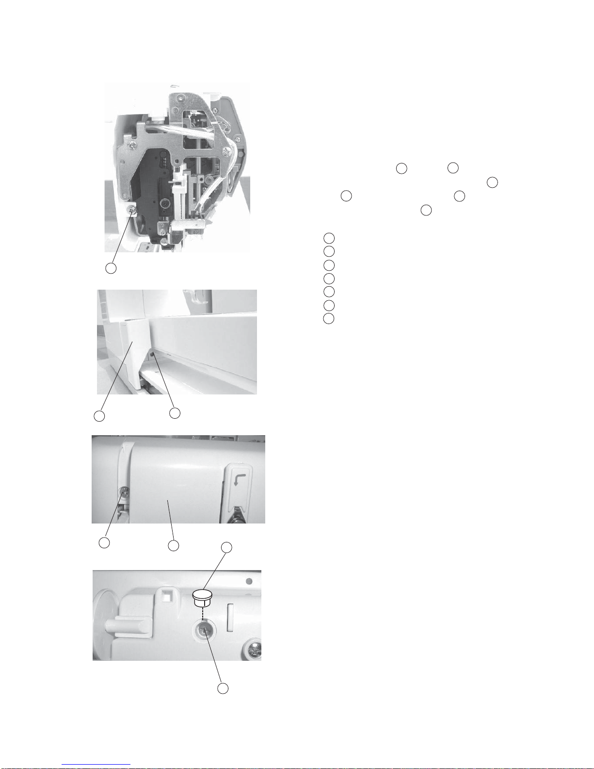
Changing External Parts (1) Face Cover................................................................. 1
Changing External Parts (2) Belt Cover..................................................................... 2
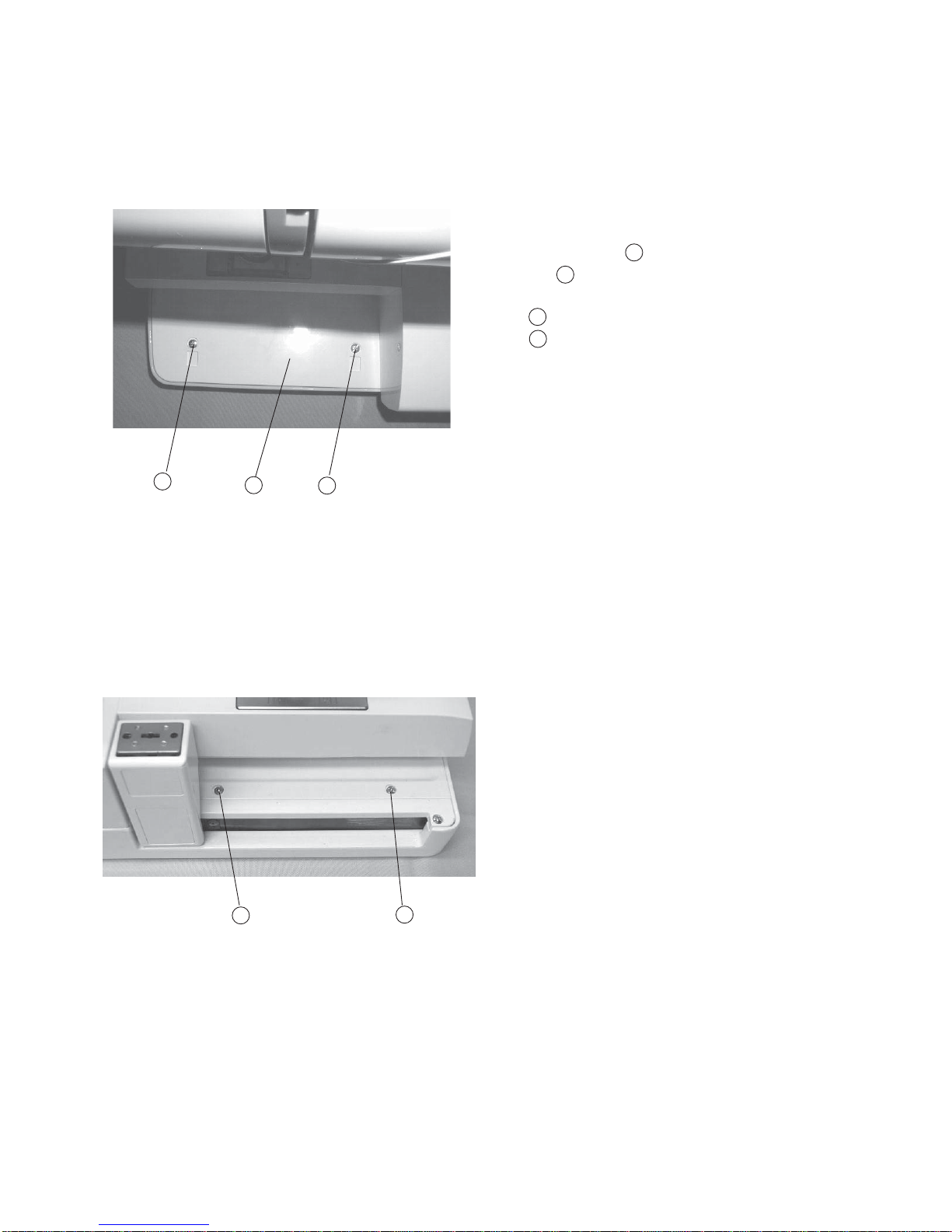
Changing External Parts (3) Base Cover................................................................... 3
Changing External Parts (4) Bed Cover/ Base Cap................................................... 4
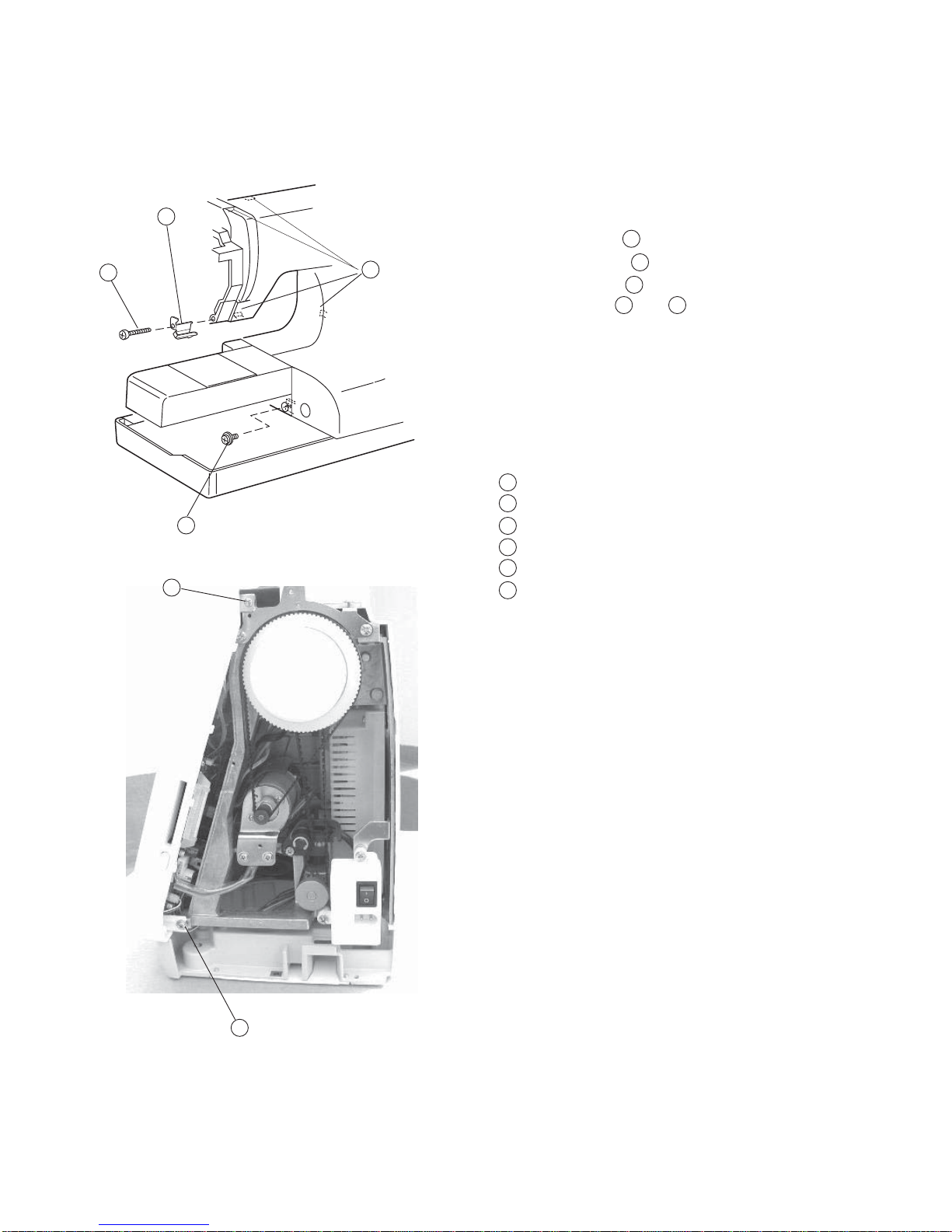
Changing External Parts (5) Base Unit...................................................................... 5
Changing External Parts (6) Front Cover................................................................... 6
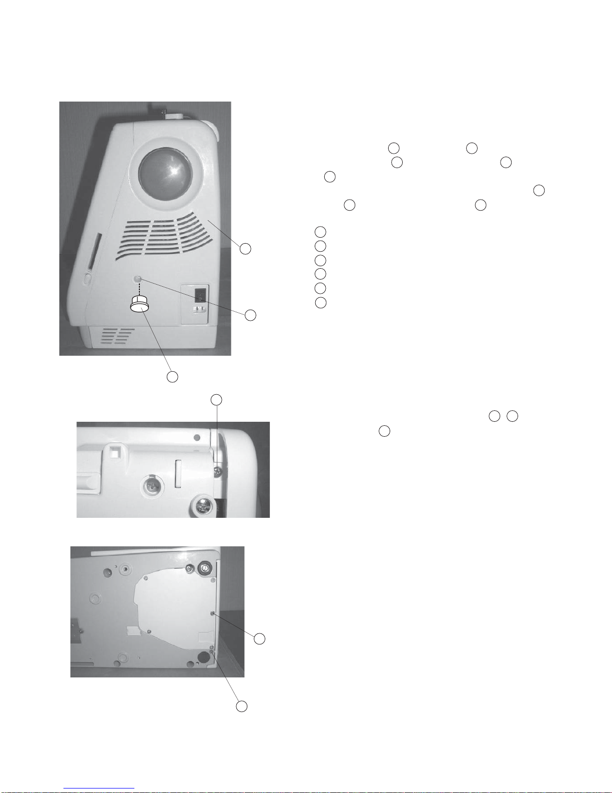
Changing External Parts (7) Rear Cover .................................................................. 7
Adjusting Needle Drop Position ................................................................................. 8
Adjusting Hook Timing ............................................................................................... 9
Adjusting Needle Bar Height..................................................................................... 10
Adjusting Clearance between Needle and Hook ...................................................... 11
Adjusting Backlash between Hook Drive Gear and Lower Shaft Gear ..................... 12
Adjusting Upper Shaft Shield Plate Position ............................................................. 13
Adjusting Nedle Thread Tension ............................................................................... 14
Adjusting Tension Release Mechanism for Knee Lifter............................................. 15
Changing Thread Tension Unit.................................................................................. 16
Replacing Threader Plate and Adjustment ............................................................... 17
Adjusting Height of Embroidery Foot P..................................................................... 18
ADJUSTMENT FOR ELECTRICAL COMPONENTS
Connector Connection Diagram................................................................................ 19
Replacing Printed Circuit Board................................................................................ 20
Replacing Touch Panel ............................................................................................. 21
Replacing Printed Circuit Board F ............................................................................ 22
Adjusting Slide Volume ............................................................................................. 23
Replacing DC Motor and Motor Belt Tension Adjustment......................................... 24
Replacing Carriage Plate (Unit) ................................................................................ 25
Adjusting X andY Sensors ....................................................................................... 26
Adjusting X andY Sensors (Instant Adjustment) ...................................................... 27
Adjusting X Motor Gear ............................................................................................ 28
Replacing Switching Power Supply........................................................................... 29
TABLE OF CONTENTS

1
Changing External Parts (1) Face Cover
To remove:
1. Remove the Cap and Screw (A) and remove
the Face Cover .
Cap
Screw (A)
Face cover
To attach:
2. Attach the Face Cover and tighten Screw (A) ,
then attach the Cap .
Replacing the face cover
3
12
1
2
3
12
3
3 2
1

2
Changing External Parts (2) Belt Cover
Replacing the belt cover
To remove:
1. Remove the Cap and Screw (A) .
2. Loosen Screw (B) and remove Screw (C) and
D .
3.Turn the machine to the back and remove Screws C
and D , then remove the Belt cover .
Cap
Screw (A)
Screw (B)
Screw (C)
Screw (D)
Belt cover
To attach:
4. Attach the Belt Cover with Screws (A - D) - .
5. Attach the Cap .
1
2
6
3
4
5
1 2
3 4
5
64
5
2 5
1
1
2
3
4
5
6

3
Changing External Parts (3) Base Cover
Replacing the base cover
To remove:
1RemoveScrews (4 pieces) to remove the base
cover .
Screw
Base cover
To attach:
2Follow the above procedure in reverse.
1
2
1
1
2
1
1
1
2

4
Changing External Parts (4) Bed Cover / Base Cap
Replacing the bed cover
To remove:
1 Remove the base cover.
2Remove Screw (A) (2 pcs.), and remove the Base
Lid .
3 Remove Screw (B) (2 pcs.), and remove the Bed
cover .
Screw (A)
Base lid
Screw (B)
Bed cover
To attach:
4Follow the above procedure in reverse.
Replacing base cap
To remove:
1 Remove Screws (4 pieces), and remove the
Lid (2) .
Setscrew
Base lid (2)
To attach:
2Follow the above procedure in reverse.
1
23
4
41
3
2
1
2
1
2
1
1
1
2
1
2
3
4

5
Changing External Parts (5) Base Unit
Base
To remove:
1 Remove the Belt cover. (See page 2)
2Remove Setscrew (A) (4 pcs.), and remove
the base unit .
3Remove the X Motor ,Y Motor Connectors
from the printed circuit board (A).
Screw (A)
X-motor connector (Blue)
Y- motor connector (White)
Connecting Bushing
Extension table (Accessory)
Screw (B)
To attach:
4Attach the X,Y - Motor Connectors , into
the printed circuit board (A)
5 Insert the X,Y - Motor Cords between the printed
cuircuit board (A) and Arm without touching the jointing
points between arm and base, then tighten Screws
(4 pieces) temporarily.
6Attach the Extension (Accessory) table .
7Tighten Screws (B) while aligning the extension
table, base unit and free Arm.
8 Tighten Screws while aligning the extension table.
9 Attach the belt cover.
1
2
3
4
1
23
1
1
23
4
5
6
1
5
6
1
23
5
6

6
To remove:
1Remove the face cover, belt cover, base cover and bed
cover. (See page 1 - 4).
2Remove Screw (A) and remove the Arm
thread guide (lower) .
3Remove Screw (B) .
4 Loosen Screw (C) , (D) .
5Disconnect the each connector and remove the front
cover.
Note: Disconnect the Hooks while removing the Front
cover.
Screw (A)
Arm thread guide (Lower)
Screw (B)
Screw (C)
Screw (D)
Hooks (4 spots)
To attach:
6Follow the above procedure in reverse.
Note: See page 21 (Diagram) for Connectors
Connection.
Changing External Parts (6) Front Cover
Front cover
1
2
2
1
4
3
6
5
2
1
4
3
6
5
3
4 5

7
Changing External Parts (7) Rear Cover
1Remove the face cover and belt cover.
2Loosen Screw (A) , and (B) .
3 Raise the handle and remove Screw (C) , and
Cap , then remove Screw (D) .
Remove the Rear cover .
Screw (A)
Screw (B)
Carriage
Screw (C)
Rear cover
Cap
Screw (D)
To attach:
3Follow the above procedure in reverse.
Rear cover
To remove:
2
1
4
3
6
5
7
2
1
4
3
6
5
7
2
14
657

8
Adjusting Needle Drop Position
1Select the pattern No.1 (Straight stitch) and lower
the needle to its lowest position by turning the
handwheel.
2 Remove the face cover and loosen Screw ,
move the Needle bar supporter to the right or
left until the needle comes to the center of the
Needle plate hole .
3 Tighten the Screw .
4Attach the face cover.
Screw
Needle bar supporter
Needle
Nedle plate hole
When the straight stitch is selected on the touch panel, the needle should be positioned at
the center of the needle plate hole.
2
1
4
32
1
3
4
1
2
3
4
1

9
Adjusting HookTiming
The hook timing is that amount of ascending travel of the needle bar from its lowest position
where the tip of the rotary hook meets the right side of the needle should be 3.1 to 3.7 mm.
1Remove the belt cover, bed cover, base cover, base
lid (1) and base lid (2).
2Remove the needle, presser foot, Needle plate (A)
and Bobbin holder (B) .
3Lower the needle bar at its lowest position by turning
the handwheel toward you.
4Raise the needle bar further 3.1 to 3.7 mm from
the lowest position.
5 Loosen the screws of lower shaft gear, turn the Lower
shaft gear until the tip of rotary hook meets with
the right side of the Needle .
Tighten Screw (2 pieces) of the lower shaft gear.
6 Attach the Bobbin holder , Needle plate ,
presser foot and Needle .
7 Attach the base lid (2), base lid (1) base cover, bed
cover and belt cover.
Needle plare (1)
Bobbin holder (B)
Screw (C)
Lower shaft gear
Needle #14
Match the tip of rotary hook and the right side of
the needle.
3.1 to 3.7 mm
Lowest position
2
1
3
4
6
7
8
21
3
45
8
5
2
1
3
4
6
5
7
8
3
21
5

10
Adjusting Needle Bar Height
1Remove the needle, presser foot, Needle plate (A)
and Bobbin holder (B) .
2Remove the face cover.
3 Rotary hook meets the Right side of the needle
in ascending travel of needle from its lowest position
by turning the handwheel toward you.
4Loosen Screw as shown.
5Move the Needle bar up or down to adjust the
needle bar height.
6 Place the Needle bar groove in front of you and
tighten Screw .
7Attach the Bobbin holder (B) , Needle plate (A) ,
presser foot and needle.
8Attach the face cover.
Needle plate (A)
Bobbin holder (B)
Screw
Needle bar
Groove
Needle # 14
Matching point
Surface of hook race
1.6 - 2.0 mm
Rotary hook race
Top of needle hole
The standard distance between the upper edge of the needle eye and the tip of the rotary
hook should be in the range of 1.6 - 2.0 mm when the rotary hook meets the right side of the
needle in ascending travel of needle from its lowest position.
2
1
3
4
6
5
7
89
10 11
1
2
7
3
4
5
6
2 1
2
1
3
4
6
5
7
8
9
10
11

11
Adjusting Clearance between Needle and Hook
The clearance between needle and rotary hook should be -0.10 to + 0.05 mm.
1Remove the needle plate, bobbin holder, base cover
and bed cover (See page 3 - 4), and attach the Test
pin .
2 Loosen Screw (A) , (B) , (C) and tighten
Screw (C) temporarily.
3Turn the handwheel toward you and adjust the
clearance between the Test pin and the Tip of
rotary hook position to - 0.10 to + 0.05 mm by
moving the rotary hook set plate up or down.
4 Tighten the screws (A) ,(B) , (C) firmly.
5Check the rotary hook driver gear and the lower shaft
gear backlash.
If gears mesh or engage tightly or loosely, check
“Adjusting Backlash between Hook Drive and Lower
Shaft Gear”. (See page 12 )
6Reattach the bed cover, base cover, base lid, needle
plate and bobbin holder.
Screw (A)
Screw (C)
Rotary hook set plate
Screw (B)
Test pin
- 0.10 to +0.05 mm
Tip of rotary hook
21
3
4
6
5
7
2
1
3
4
6
5
7
2
1
34
6
5
7
2
5
1
42

12
Adjusting Backlash between Hook Drive Gear and Lower
Shaft Gear
The backlash of gears should be 0.8 mm or less when the tip of the rotary hook is within the
width of the feed dog as shown below.
Adjust the backlash after the adjustment of the clearance between needle and rotary hook.
1 Remove the base cover, base lid and bed cover. (See
page 3 - 4)
2 Loosen the Hexagonal socket screw .
3 (A) If the backlash is too big or too large,
turn the lower shaft bushing in the direction of A.
(B) If the backlash is too little,
turn the lower shaft bushing in the direction of B.
4Tighten the Hexagonal socket screw .
5 Reattach the bed cover, base cover, and base lid.
Lower shaft bushing
Hexagonal socket screw
Backlash should be 0.8 mm or less.
A
B
1
2
3
1
2
1
2
1
2
3

13
Adjusting Upper Shaft Shield Plate Position
1Remove the front cover unit. (See page 6)
2 (A) If the needle is higher than 14.2 mm, loosen
Screw and turn the Upper shaft shield plate
in the direction of (A).
(B) If the needle stops lower than the 14.2 mm ,
loosen Screw and turn the Upper shaft
shield plate in the direction of (B).
3 Place the right hand of the Upper shaft shield plate
at the center position of the Upper shaft sensor
and tighten Setcrew .
4Turn the handwheel toward you to check the needle
position again, then attach the front cover.
Screw
Upper shaft shield plate
14.2 mm
Upper shaft sensor
Needle #11
The standard height of needle stop position should be 14.2 mm above the needle plate
surface when the machine is topped.
(A)
(B)
1
3
2
2
4
1
2
3
5
1
2
14
1
2
3
4
5

14
Adjusting Needle Thread Tension
The standard of upper thread tension should be 51 g to 59g when pulling the thread
(cotton thread #50) in the direction of A when
1Set the Thread tension dial at “3”.
2Lower the presser foot.
3Remove the front cover unit and adjust the thread
tension.
(A) If the thread tension is 59g or more
.................turn the screw in the direction of “B”.
(B) If the thread tension is 51 g or less
...............turn the screw in the direction of “A”
Pull the #50 cotton thread in the direction
of the arrow. (Pulling speed 110 mm/ Sec.)
(A)
(B)
1
1

15
AdjustingTension Release Mechanism for Knee Lifter
1 Remove the front cover unit. (see page 6)
2Lower the presser foot lifter, set the thread tension dial
at “9” and loosen the Screw (A) .
3Adjust the play approximately 0.3 - 0.5 mm between
the tension release rod (2) and the spring
holder and tighten the Screw (A) .
4Raise the presser foot lifter, turn the thread tension
dial from “9” to “0”, make sure the clearance
between the tension discs should be 1.0 mm .
5Reattach the front cover unit.
Screw (A)
Tension release rod (2)
Play (0.3 - 0.5 mm)
Spring holder
Tension discs
Clearance (approximately 1.0 mm)
1
2
3
2
4
5
6
When the presser foot lofter is raised, the tension release mechanism should work
correctly. If not, adjust as follows.
1
2
3
4
5
6
1
3
4 1
5 6

16
ChangingThreadTension Unit
To remove:
1Remove the front cover unit. (See page 6)
2 Remove Setscrew (A) , (B) , and remove
the thread tension dial.
To attach:
3Follow the above procedure in reverse.
Note: After the replacement, adjust “Thread Tension
Release Machanism” and Adjustment of
Solenoid”.
Screw (A)
Screw (B)
12
Replacing the thread tension unit
1
2
2
1

17
ReplacingThreader Plate and Adjustment
If the hook on the threader plate is damaged, replace it by following the instructions below.
Replacing threader plate
1. Remove the presser foot.
2. Push down the Threader supporter plate (A) to
remove from the Pin (B) . (Drawing 1.)
3. Toattachthethreadersupporter plate,matchthegroove
of the Threader supporter with the pin , and
then push it up to insert.
Threader supporter (A)
Pin (B)
Hook
Adjusting threader plate position
1When the hook is slightly touching the nedle eye,
loosen Screw (C) and adjust the Threader plate
as shown.
If the hook position is too high or too low
1Remove the face cover.
2 If the hook is too high, loosen the screw (D) and
lower the Setting position plate .
If the hook is too low, loosen Screw (D) to
slide up the Setting position plate .
Screw (C)
Threader plate
Screw (D)
Setting position plate
Needle bar
1
2
3
21
1
2
3
(X)View
(X)
DRAWING 1
DRAWING 2
DRAWING 3
1
2
3
4
1
2
3
4
5
43
2
1
4
3
5
1
2

18
Adjusting Height of Embroidery Foot P
Attach the Foot (P), and the space between the needle plate and the bottom surface of the
Foot (P) should be 1.0 to 1.6 mm, when the needle bar is at its lowest position.
1Remove the front cover unit. (See page 6)
2Lower the needle bar and lower the presser foot lifter.
3 Insert the 1.2 mm Thickness gauge between
the Embroidery Foot (P) and the needle plate.
4While pressing the Pressure bar actuator down
against the upper shaft cam, and tighten Screw (A)
again.
5Reattach the rear cover.
Thickness gauge
Embroidery foot (P)
Pressure bar Actuator
Screw (A)
Needle
Needle plate
3
4
2
1
1
2
3
4
5
6
5
1
2
3
4
6
Table of contents
Other ELNA Sewing Machine manuals

ELNA
ELNA eXcellence 580+ User manual

ELNA
ELNA EXPRESSIVE 820 User manual

ELNA
ELNA 3210 User manual

ELNA
ELNA XQUISIT 2 User manual

ELNA
ELNA 8200 User manual

ELNA
ELNA eXcellence 780 User manual

ELNA
ELNA eXpressive 900 Technical manual

ELNA
ELNA 434 - LEAFLET User manual

ELNA
ELNA 5200 User manual

ELNA
ELNA 7300 - User manual