elock KC1005-4 BW User manual

Door Closer
KC1005-4 BW
Overview :
KC1005-4 BW door closer is made of die casting alloy
aluminum, designed with simple and graceful in appearance.
Features :
Closing speed can be adjusted independently
Latching speed can be adjusted independently
BW have back check function and adjustable speed
BW are provided with back check and closing force
adjustment functions.
Specification :
Door Closer
KC1005-4 BW
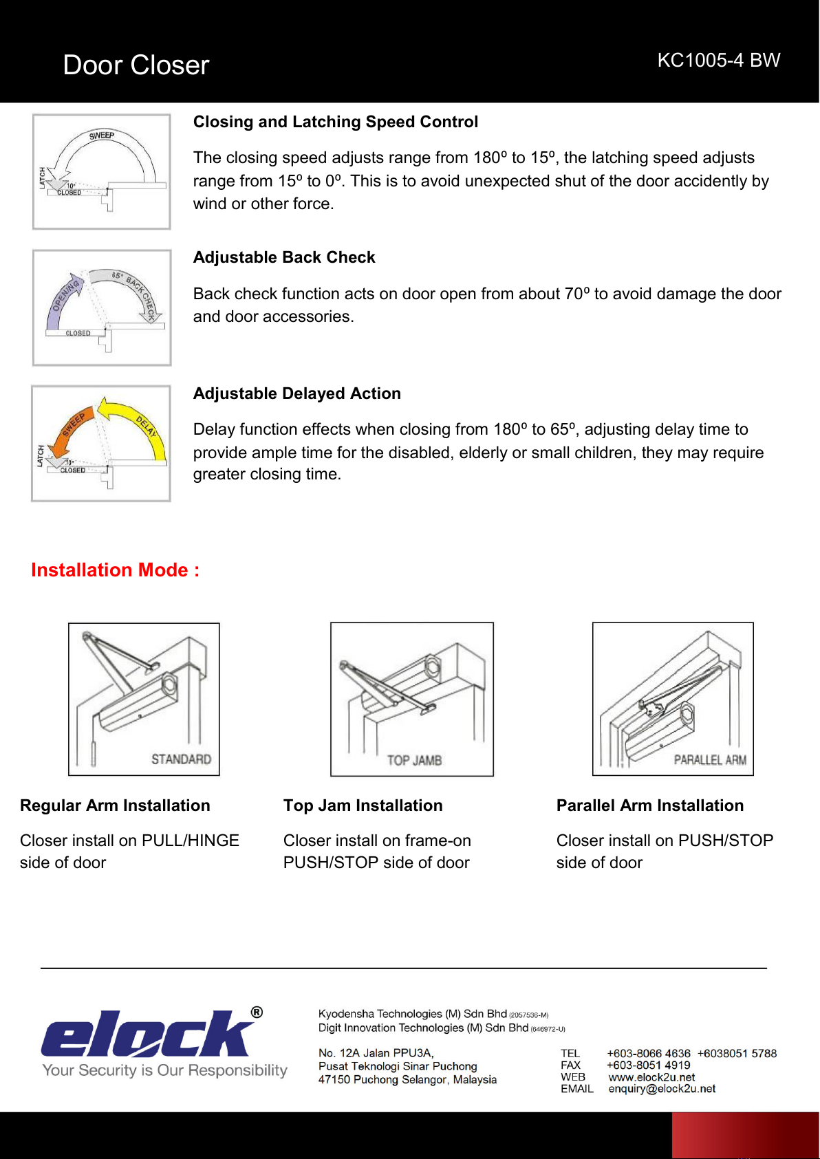
Closing and Latching Speed Control
The closing speed adjusts range from 180⁰to 15⁰, the latching speed adjusts
range from 15⁰to 0⁰. This is to avoid unexpected shut of the door accidently by
wind or other force.
Adjustable Back Check
Back check function acts on door open from about 70⁰to avoid damage the door
and door accessories.
Adjustable Delayed Action
Delay function effects when closing from 180⁰to 65⁰, adjusting delay time to
provide ample time for the disabled, elderly or small children, they may require
greater closing time.
Installation Mode :
Regular Arm Installation
Closer install on PULL/HINGE
side of door
Top Jam Installation
Closer install on frame-on
PUSH/STOP side of door
Parallel Arm Installation
Closer install on PUSH/STOP
side of door
Door Closer
KC1005-4 BW
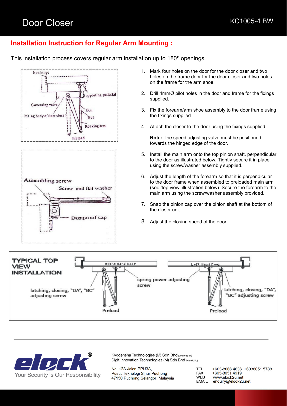
Installation Instruction for Regular Arm Mounting :
This installation process covers regular arm installation up to 180⁰openings.
1. Mark four holes on the door for the door closer and two
holes on the frame door for the door closer and two holes
on the frame for the arm shoe.
2. Drill 4mmØ pilot holes in the door and frame for the fixings
supplied.
3. Fix the forearm/arm shoe assembly to the door frame using
the fixings supplied.
4. Attach the closer to the door using the fixings supplied.
Note: The speed adjusting valve must be positioned
towards the hinged edge of the door.
5. Install the main arm onto the top pinion shaft, perpendicular
to the door as illustrated below. Tightly secure it in place
using the screw/washer assembly supplied.
6. Adjust the length of the forearm so that it is perpendicular
to the door frame when assembled to preloaded main arm
(see ‘top view’illustration below). Secure the forearm to the
main arm using the screw/washer assembly provided.
7. Snap the pinion cap over the pinion shaft at the bottom of
the closer unit.
8. Adjust the closing speed of the door

Door Closer
KC1005-4 BW
Installation Instruction for Top Jamb Mounting :
This installation process covers top jamb installation up to 180⁰openings.
1. Mark four holes on the door for the door closer and two
holes on the frame door for the door closer and two holes on
the frame for the arm shoe.
2. Drill 4mmØ pilot holes in the door and frame for the fixings
supplied.
3. Fix the forearm/arm shoe assembly to the door frame using
the fixings supplied.
4. Attach the closer to the door using the fixings supplied.
Note: The speed adjusting valve must be positioned
towards the hinged edge of the door.
5. Install the main arm onto the top pinion shaft, perpendicular
to the door as illustrated below. Tightly secure it in place
using the screw/washer assembly supplied.
6. Adjust the length of the forearm so that it is perpendicular to
the door frame when assembled to preloaded main arm (see
‘top view’illustration below). Secure the forearm to the main
arm using the screw/washer assembly provided.
7. Snap the pinion cap over the pinion shaft at the bottom of
the closer unit.
8. Adjust the closing speed of the door
Door Closer
KC1005-4 BW
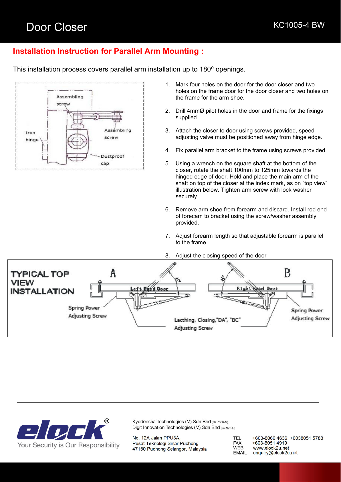
Installation Instruction for Parallel Arm Mounting :
This installation process covers parallel arm installation up to 180⁰openings.
1. Mark four holes on the door for the door closer and two
holes on the frame door for the door closer and two holes on
the frame for the arm shoe.
2. Drill 4mmØ pilot holes in the door and frame for the fixings
supplied.
3. Attach the closer to door using screws provided, speed
adjusting valve must be positioned away from hinge edge.
4. Fix parallel arm bracket to the frame using screws provided.
5. Using a wrench on the square shaft at the bottom of the
closer, rotate the shaft 100mm to 125mm towards the
hinged edge of door. Hold and place the main arm of the
shaft on top of the closer at the index mark, as on “top view”
illustration below. Tighten arm screw with lock washer
securely.
6. Remove arm shoe from forearm and discard. Install rod end
of forecam to bracket using the screw/washer assembly
provided.
7. Adjust forearm length so that adjustable forearm is parallel
to the frame.
8. Adjust the closing speed of the door
Door Closer
KC1005-4 BW
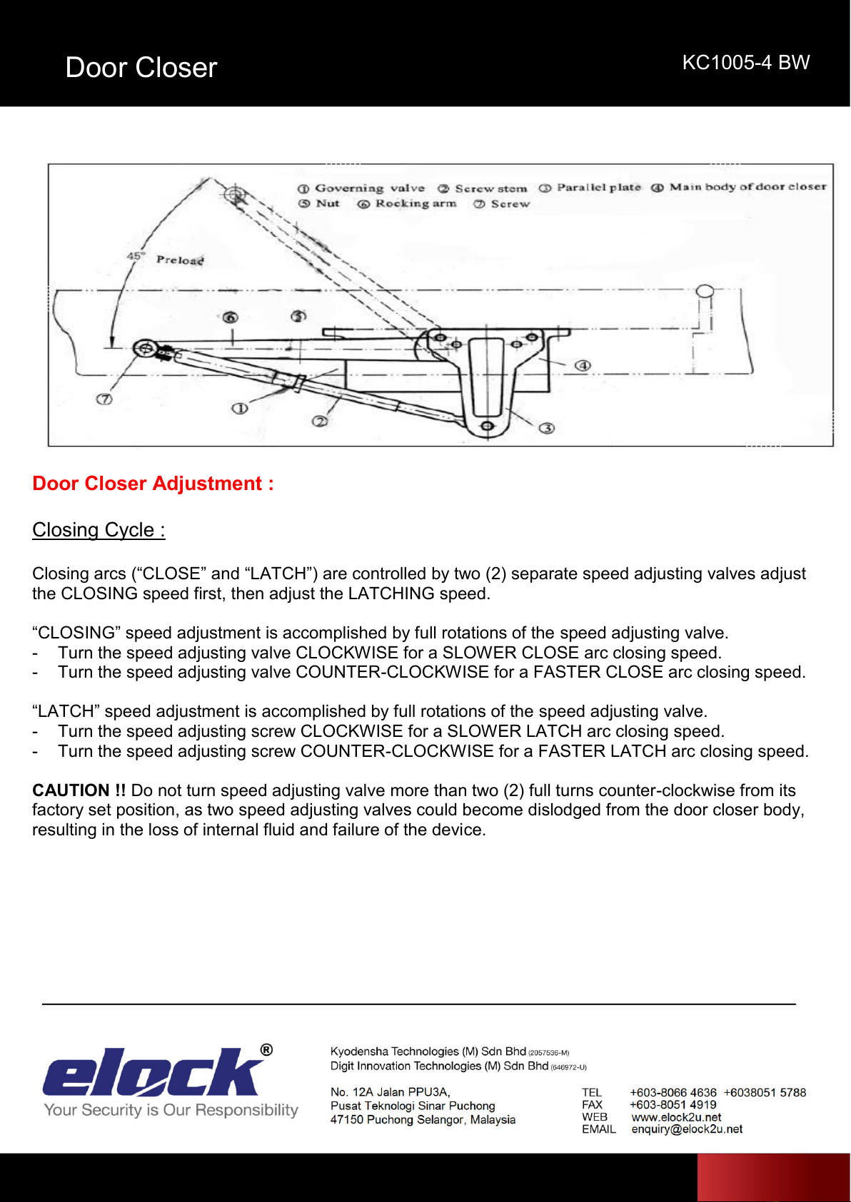
Door Closer Adjustment :
Closing Cycle :
Closing arcs (“CLOSE”and “LATCH”) are controlled by two (2) separate speed adjusting valves adjust
the CLOSING speed first, then adjust the LATCHING speed.
“CLOSING”speed adjustment is accomplished by full rotations of the speed adjusting valve.
- Turn the speed adjusting valve CLOCKWISE for a SLOWER CLOSE arc closing speed.
- Turn the speed adjusting valve COUNTER-CLOCKWISE for a FASTER CLOSE arc closing speed.
“LATCH”speed adjustment is accomplished by full rotations of the speed adjusting valve.
- Turn the speed adjusting screw CLOCKWISE for a SLOWER LATCH arc closing speed.
- Turn the speed adjusting screw COUNTER-CLOCKWISE for a FASTER LATCH arc closing speed.
CAUTION !! Do not turn speed adjusting valve more than two (2) full turns counter-clockwise from its
factory set position, as two speed adjusting valves could become dislodged from the door closer body,
resulting in the loss of internal fluid and failure of the device.

Door Closer
KC1005-4 BW
Back Check Control
To increase back check intensity, turn
back check control valve clockwise.
To decrease back check intensity, turn
back check control valve anticlockwise
Spring Power Control
To increase opening force and closing
force, turn the spring adjusting nut
clockwise.
To decrease opening force and closing
force, turn the spring adjusting nut
anticlockwise.
Table of contents
Popular Door Opening System manuals by other brands

Kesseböhmer
Kesseböhmer eTouch DISPENSA operating instructions

hager
hager 4500 Series installation instructions

GEZE
GEZE RSZ6 Wiring diagram

WSS
WSS SPRINT Slide Line Original Assembly and Maintenance Instructions

Record
Record FlipFlow TWIN user manual

Roger Technology
Roger Technology R41 Series Instructions and Recommendations

Daihatsu
Daihatsu EDM18ZII instruction manual

Mantion
Mantion SLID'UP 2500 Instructions for assembly

Assa Abloy
Assa Abloy Yale 1105 installation instructions

Automatic Technology
Automatic Technology GDO-12Hir Quick operation guide

Beninca
Beninca VN.S20E Operating instructions and spare parts catalogue

Assa Abloy
Assa Abloy Adams Rite EX88 Preparation Guide and Installation Instructions


