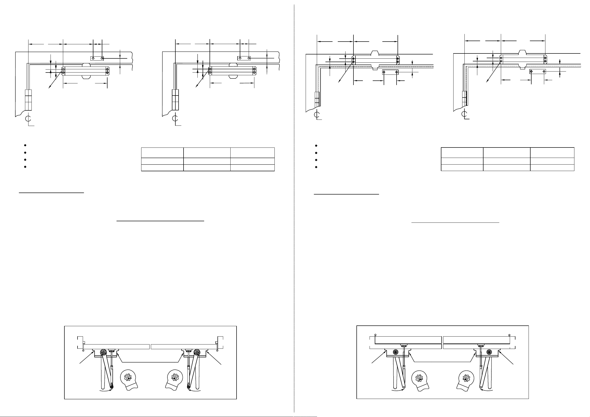
3/4(19)
A
B
9-1/16(230)
OPENING
To120°
120°-180°
DIM.A
9-3/8(238)
7-3/16(183)
DIM.B
7-13/16(198)
5-5/8(143)
DIM.A DIM.B
6-15/16(176)
4-3/4(121)
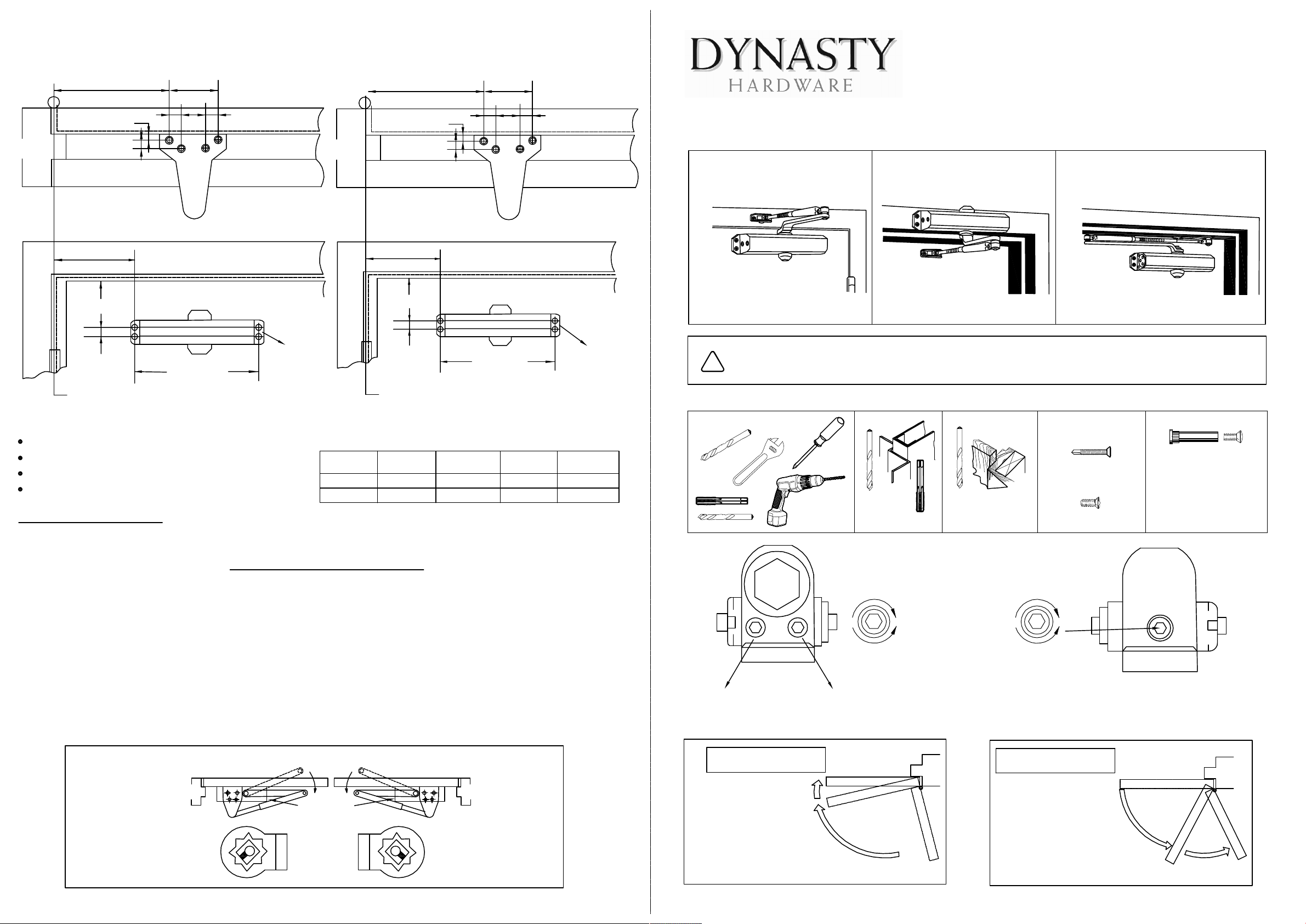
PARALLEL ARM (PUSH SIDE) Mounting DYN-2000, DYN-3000, DYN-4000
DOOR CLOSERS
INSTALLATION INSTRUCTIONS
Non-Hold open
PAGE 1
Size 2&3
5/16(8)
7/16(11)
3/8(9.5) 3/8(9.5mm)
2(50.8)
2-3/4(69.8)
3/4(19)
A
B
8-3/16(208)
3-3/8(85.7)
5/16(8)
7/16(11)
3/8(9.5) 3/8(9.5)
2(50.8)
2-3/4(69.8)
Size 4 Size 4
DYN-4000DYN-2000,DYN-3000
Size 2&3
Regular Arm Installation
Closer installs on PULL/HINGE
side of door
Top Jamb Installation
Closer Installs on Frame on
PUSH/STOP side of door.
Parallel Arm Installation
Closer installs on PUSH/STOP
side of door. * Optional
illustrated
Non Hold Open Arm
Left Hand Door-LH
Right Hand Reverse -RHR
See Page 2
illustrated
Non Hold Open Arm
Right Hand Door-RH
Left Hand Reverse -LHR
See Page 3
illustrated
Non Hold Open Arm
Right Hand Door-RH
Left Hand Reverse -LHR
See Page 4
Hinge Edge
of Door
Hinge Edge
of Door
1. Select degree of opening and use dimensions shown or attached template to locate 4 holes on door for closer body and 4
holes underside of frame for P.A plate.
2. Prepare door and frame for fasteners. See "Preparation for Fasteners", Figure 1, Page 1.
3. Mount closer on door using provided screws.
SPEED ADJUSTING VALVE MUST BE POSITIONED AWAY FROM HINGE EDGE
4. Install parallel Arm Bracket to frame using provided screws.
5. Using a wrench on the square shaft at bottom of closer, rotate shaft approximately 45 degrees toward hinge edge of door.
Hold and place main arm on top shaft of closer at proper index mark as illustrated.
FOR LEFT HAND DOOR "L"(illustration "A"). FOR RIGHT HAND DOOR "R"(illustration "B").
Tighten arm screw with Lock-washer securely.
6. Remove arm shoe from forearm and discard. Install rod end of forearm to bracket using provided screw/washer assembly.
7. Adjust length of adjustable forearm so that main arm is parallel to frame.
8. Adjust the door closer, following instructions as shown on page 1.
INSTALLATION SEQUENCE
(A) (B)
Parallel arm Installation
Speed screws
Right hand door
Left hand door
S
R
L
S
L
R
45° 45°
Left hand door shown
Right hand door opposite
Dimensions are in inches (mm)
Do not scale drawing
Hinge
or
Pivot
PAGE 4
3-3/8(85.7)
9-3/8(238)
7-3/16(183)
21
CLOSING VALVE
LATCH VALVE
Never close This
valve completely
BC*
Latch
10°
Caution: Do not back valves out of
closer or a leak will result.
Closed
Closing
Standard closing cycle
ATTENTION:
Adjust closing time between
4 to 6 seconds from 90°.
USE of the door by
handcapped,elderly or small
children may require longer
closing time.
Closed
Opening
Backcheck
ATTENTION:
Backcheck(BC) valve controls the
hydraulic resistance to door opening in
backcheck range. NEVER close this
valve completely.
It is not to provide a positive stop.
Door opening control
Caution: Do not back valves out of
closer or a leak will result.
Door closing control
Slow
Fast
Stronger
Weaker
TOOLS REQUIRED METAL
#7
1/4"-20
WOOD
3/16"
*Pilot Hole Required
Self Drilling /Tapping
screws
Wood and Metal
For wood, drill 3/16" hole
Machine Screws
#7 Drill, 1/4"-20 Tap
Sleeve Nut and Bolt
Drill 9/32" thru from
Closer side
3/8" Drill other Side
Check building and fire
codes to see if your
application requires the
use of sleeve nuts and
bolts.
Preparation for Fasteners-Figure 1.
Please read this installation instruction carefully before installation
We won't be responsible for any results which are caused by improper installation
!
Caution
DOOR CLOSER ADJUSTMENT
Speed
valves
Speed
valves
Hinge
or
Pivot
* Optional