ELPRO 105U User manual

User Manual
105U-G Wireless Gateway
AUDIN
Composants & systèmes d'automatisme
8, avenue de la malle 51370 Saint Brice Courcelles - France
Tel. +33(0)326042021 • Fax +33(0)326042820
http://www.audin.fr • e-mail info@audin.fr

Important Notices
MAN_105G_1.5 Page 2
Thank you for your selection of the 105G module. We trust it will give you
many years of valuable service.
ATTENTION!
Incorrect termination of supply wires may
cause internal damage and will void warranty.
To ensure your 105G enjoys a long life,
double check ALL your connections with
the user’s manual
before turning the power on.

105U-G Wireless Gateway User Manual
Page 3©August 2003
Important Notice
ELPRO products are designed to be used in industrial environments, by experienced
industrial engineering personnel with adequate knowledge of safety design considerations.
ELPRO radio products are used on unprotected licence-free radio bands with radio noise and
interference. The products are designed to operate in the presence of noise and interference,
however in an extreme case, radio noise and interference could cause product operation
delays or operation failure. Like all industrial electronic products, ELPRO products can fail
in a variety of modes due to misuse, age, or malfunction. We recommend that users and
designers design systems using design techniques intended to prevent personal injury or
damage during product operation, and provide failure tolerant systems to prevent personal
injury or damage in the event of product failure. Designers must warn users of the equipment
or systems if adequate protection against failure has not been included in the system design.
Designers must include this Important Notice in operating procedures and system manuals.
These products should not be used in non-industrial applications, or life-support systems,
without consulting ELPRO Technologies first.
1. For 105G modules, a radio licence is not required in most countries, provided the
module is installed using the aerial and equipment configuration described in the 105U
Installation Guide. Check with your local 105G distributor for further information on
regulations.
2. For 105G modules, operation is authorised by the radio frequency regulatory authority
in your country on a non-protection basis. Although all care is taken in the design of
these units, there is no responsibility taken for sources of external interference. The
105U intelligent communications protocol aims to correct communication errors due
to interference and to retransmit the required output conditions regularly. However
some delay in the operation of outputs may occur during periods of interference.
Systems should be designed to be tolerant of these delays.
3. To avoid the risk of electrocution, the aerial, aerial cable, serial cables and all
terminals of the 105G module should be electrically protected. To provide maximum
surge and lightning protection, the module should be connected to a suitable earth and
the aerial, aerial cable, serial cables and the module should be installed as
recommended in the Installation Guide.
4. To avoid accidents during maintenance or adjustment of remotely controlled
equipment, all equipment should be first disconnected from the 105U module during
these adjustments. Equipment should carry clear markings to indicate remote or
automatic operation. E.g. "This equipment is remotely controlled and may start
without warning. Isolate at the switchboard before attempting adjustments."
5. The 105G module is not suitable for use in explosive environments without additional
protection.

Contents
MAN_105G_1.5 Page 4
Limited Warranty, Disclaimer and Limitation of Remedies
ELPRO products are warranted to be free from manufacturing defects for a period of 2 years
from the effective date of purchase. The effective date of purchase is decided solely by
ELPRO Technologies.
This warranty does not extend to:
- failures caused by the operation of the equipment outside the particular product's
specification, or
- use of the module not in accordance with this User Manual, or
- abuse, misuse, neglect or damage by external causes, or
-repairs, alterations, or modifications undertaken other than by an authorised Service
Agent.
ELPRO’s liability under this warranty is limited to the replacement or repair of the product.
This warranty is in lieu of and exclusive of all other warranties. This warranty does not
indemnify the purchaser of products for any consequential claim for damages or loss of
operations or profits and ELPRO is not liable for any consequential damages or loss of
operations or profits resulting from the use of these products. ELPRO is not liable for
damages, losses, costs, injury or harm incurred as a consequence of any representations,
warranties or conditions made by ELPRO or its representatives or by any other party, except
as expressed solely in this document.
How to Use This Manual
To receive the maximum benefit from your 105U-G product, please read the Introduction,
Installation and Operation chapters of this manual thoroughly before using the 105U-G.
Chapter Four Configuration explains how to configure the modules using the Configuration
Software available.
Chapter Six Troubleshooting will help if your system has problems.
The foldout sheet 105U-G Installation Guide is an installation drawing appropriate for most
applications.

105U-G Wireless Gateway User Manual
Page 5©August 2003
CONTENTS
CHAPTER 1 INTRODUCTION 7
1.1 105G OVERVIEW 7
1.1.1 Modbus / DF1 105G 8
1.1.2 Profibus 105G 8
1.1.3 Ethernet 105G 9
1.2 THE 105G STRUCTURE 9
1.2.1 On-board I/O 10
1.3 THE WIRELESS NETWORK 11
1.3.1 105U to 105G Network 11
1.3.2 105G to 105G Network 12
1.3.3 “Data Concentrator” Networks 13
CHAPTER 2 OPERATION 14
2.1 START-UP 14
2.2 OPERATION 14
2.3 DATABASE 16
2.4 THE HOST - 105G LINK 17
2.4.1 Modbus / DF1 18
2.4.2 Profibus 18
2.4.3 Ethernet 18
2.5 RADIO SYSTEM DESIGN 19
2.5.1 Radio Signal Strength 19
2.5.2 Repeaters 19
2.6 RADIO COMMS FAILURE 20
2.6.1 Monitoring Communications Failure 20
2.7 SECURITY CONSIDERATIONS 21
CHAPTER 3 INSTALLATION 22
3.1 GENERAL 22
3.2 ANTENNA INSTALLATION 22
3.2.1 Dipole antenna. 23
3.2.2 Yagi antenna. 24
3.2.3 Collinear antenna. 25
3.3 POWER SUPPLY 25
3.3.1 AC Supply 26
3.3.2 DC Supply 26
3.3.3 Solar Supply 27
3.4 INPUT / OUTPUT 27
3.4.1 Digital Inputs / Outputs 27
3.5 SERIAL PORT 28
3.5.1 RS232 Serial Port 28
3.5.2 RS485 Serial Port 29
3.6 PROFIBUS PORT 29
3.7 ETHERNET PORT 30
CHAPTER 4 CONFIGURATION 31
4.1 INTRODUCTION 31
4.2 CONFIGURATION PROGRAM 32
4.2.1 Program Operation 32
4.2.2 Security 36
4.3 MAPPINGS 105G TO 105U I/O MODULES 38
4.3.1 Mappings from Inputs at Remote 105U I/O Modules 38

Contents
MAN_105G_1.5 Page 6
4.3.2 Mappings from 105G to Outputs at Remote 105U I/O Modules 40
4.3.3 Don’t Send if in Comm Fail 42
4.3.4 Startup Polls 43
4.3.5 Polls to Remote Modules 43
4.4 MAPPINGS FROM 105G TO OTHER 105G MODULES 43
4.4.1 Entering a Block Mapping 45
4.4.2 Host Device Trigger 46
4.4.3 Time Period 47
4.4.4 Real-Time 47
4.4.5 Change-of-State 49
4.4.6 Mixing Normal Mappings and Block Mappings 50
4.4.7 Comms Fail for Block Mappings 50
4.5 CHANGE SENSITIVITY 50
4.6 DATA BUS CONFIGURATION - MODBUS 51
4.5.2 MODBUS Slave 51
4.5.2 MODBUS Master 53
4.7 DATA BUS CONFIGURATION - DF1 56
4.8 DATA BUS CONFIGURATION - PROFIBUS SLAVE 60
4.9 DATA BUS CONFIGURATION - ETHERNET 63
1.1.1 Linking I/O Registers with Ethernet Bytes 64
1.1.2 Setting IP Address 65
1.1.3 Modbus TCP 67
1.1.4 Ethernet/IP 68
4.10 UPLOADING AND DOWNLOADING 73
4.10.1 Loading from a 105G 73
CHAPTER 5 SPECIFICATIONS 75
CHAPTER 6 DIAGNOSTICS 77
6.1 DIAGNOSTICS CHART 77
6.2 DIAGNOSTICS MENU 78
6.2.1 Radio signal strength measurements 79
6.2.2 Online Diagnostics 80
6.3 ETHERNET DIAGNOSTICS 84
6.4 ETHERNET / PROFIBUS INDICATING LEDS85
6.4.1 Ethernet Indicating LED’s 85
6.4.2 Profibus Indicating LED’s 86
CHAPTER 7 WARRANTY 87
APPENDIX 1 88

105U-G Wireless Gateway User Manual
Page 7©August 2003
Chapter 1 INTRODUCTION
1.1 105G Overview
The 105U-G Wireless Gateway products provide a wireless interface between various data
buses used in process and automation applications. The 105U-G includes an integral radio
transceiver suitable for licence-free operation in
many countries. The 105U-G transfers
transducer and control signals (I/O) by radio
using a highly secure and highly reliable radio
protocol.
The 105U radio protocol is designed for very
efficient radio band usage, with event reporting
communications, automatic acknowledgement
and error-correction, peer to peer addressing,
multiple path routing, and frequency encoding
and data encryption for system security.
Application types include:
•The 105U-G interfaces between 105U
wireless I/O and various data buses.
Connect wireless I/O to PLC’s, DCS,
SCADA or Internet.
•Wireless extension of factory automation
buses such as Profibus.
•Wireless interconnectivity between different
data buses - Ethernet to Profibus to Modbus
to DF1.
•Combined networks of the above.
The 105U-G has eight on-board discrete I/O. Each I/O point can be configured individually
as a contact input signal, or a discrete output signal. Input signals can sent via its data-bus
connection to a host device (PLC, DCS etc) or be transmitted by radio to other 105U units.
The output signals can be driven by a host device, or linked to inputs on remote 105U units.
This document assumes the reader is familiar with the operation of the 105U I/O modules -
for further information, please refer to the User Manuals for these products.
Profibus
Ethernet
Modbus
DF1
Internet
105U I/O
105U I/O
Direct I/O
105U-G
Direct I/O
105U-G
Profibus
105U-G
Profibus
105U-G
Profibus
Ethernet
105U I/O
105U I/O
Direct I/O
105U-G
Direct I/O
Profibus
Modbus
105U-G
105U-G
105U-G
Modbus
105U-G
Ethernet
105U-G
Profibus

Chapter One Introduction
MAN_105G_1.5 Page 8
The 105U-G is referred to as the 105G for the rest of this document, to clearly differentiate
from normal 105U I/O modules.
Ordering information:
105U-G-MD1 Modbus Master & Slave / DF1 interface
105U-G-PR1 Profibus-DP Slave interface
105U-G-ET1 Ethernet interface - Modbus TCP, Ethernet IP, FTP, HTML, Email
1.1.1 Modbus / DF1 105G
The 105U-G-MD1 can be configured for Modbus master interface, Modbus slave, or DF1.
Modbus is a PLC protocol originally developed by Modicon (now part of the Schneider
group). It became a popular interconnect protocol with many equipment manufacturers.
Modbus is a “master-slave” protocol. One Modbus master controls the Modbus network
communications, which can comprise up to 250 Modbus slave devices. The Modbus master
can read or write I/O values to/from Modbus slaves. The 105G can be configured as either
Modbus Master or Modbus Slave. The variation of Modbus supported by the 105G is
“Modbus RTU” (also known as “Modbus binary”).
DF1 is an Allen-Bradley protocol (Allen-Bradley is now part of the Rockwell Automation
group). DF1 offers both full-duplex (point to point) and half-duplex (multidrop) operation.
The 105G only supports the full-duplex operation - this is the default DF1 mode on most
equipment. DF1 full-duplex is a “peer-to-peer” protocol. Either DF1 device can initiate
commands to the other device, and both devices will respond to commands from the other
device.
The 105U-G-MD1 has two serial connections - RS232 and RS485, on the bottom end plate
of the module. The serial port provides both RS232 and RS485 hardware connections,
however both connections are paralleled internally - both connections cannot be used at the
same time. Either RS232 or RS485 can be used for Modbus communications, however only
the RS232 port can be used for DF1. The serial port must be configured to suit the host
device. Serial data rates between 1200 and 19200 baud may be selected, and character types
with 7 or 8 data bits, even/odd/none parity, and 1 or 2 stop bits may be selected.
The Modbus/DF1 105G has 4300 I/O registers. Each discrete, analogue and pulse I/O point
takes up one register.
1.1.2 Profibus 105G
The Profibus 105G provides Profibus-DP Slave functionality according to EN 50170.
Profibus is a popular automation data bus that originated in Germany and used extensively by
Siemens and other automation suppliers.
The Profibus connection on the 105G is optically isolated RS485 using an on-board DC/DC
converter. The Profibus port has automatic baudrate detection (9600 bit/s - 12 Mbit/s).
The Profibus 105G I/O database has 4300 registers (each of 16 bit value), however the
Profibus interface only supports 416 x 8 bit bytes of I/O, and this limits the amount of I/O
that can be transferred via the Profibus port. Of the 416 bytes of I/O, there is a maximum
244 input bytes and maximum 244 output bytes - that is, if 244 input bytes are used then
only 172 output bytes can be used (416 – 244). Each byte can represent 8 discrete inputs or
outputs, or an 8-bit value, or two bytes can represent a 16-bit value. That is, analogue or
pulse I/O can be transferred as 8-bit registers (1 byte) or 16-bit registers (2 consecutive bytes).

105U-G Wireless Gateway User Manual
Page 9©August 2003
An “input” is a value coming into the 105G via the data bus (that is, a value written to the
105G from the Profibus master). An output is a value going out from the 105G via the data
bus (a value read by the Profibus master).
So a Profibus 105G could handle up to 1952 (244 x 8) discrete inputs or 244 low resolution
analogue inputs or 122 (244 x ½) high resolution analogue inputs, or some combination in
between.
For example, a Profibus 105G can handle 400 discrete inputs, 240 discrete outputs, 90
analogue inputs and 60 analogue outputs (assume analogues are 16-bit). The number of input
bytes is 230 (400/8 + 90*2). The number of output bytes is 150 (240/8 + 60*2). The total
number of I/O bytes is 380. If the number of analogue outputs was increased to 90, then the
total output bytes would be 210 (240/8 + 90*2), and the total number of I/O bytes is 440 -
this exceeds the capacity of the Profibus interface.
1.1.3 Ethernet 105G
The Ethernet 105G provides several different types of Ethernet functionality:
♦Modbus TCP. Modbus TCP uses Modbus as a base protocol within an Ethernet
communications structure. The 105G provides class 0, 1 and partially class 2 slave
functionality.
♦EtherNet IP. EtherNet IP is the version of Ethernet used by Allen-Bradley devices. The
105G provides level 2 I/O server CIP (ControlNet and DeviceNet).
♦Internet functionality. The 105G has 1.4Mbyte of non-volatile “flash” memory for
embedded web “pages” (dynamic HTTP), on-board file system, user downloadable web
pages thru FTP server, and email functionality (SMTP).
The Ethernet connection is a transformer isolated RJ45 connector, 10/100 Mbit/sec.
The Ethernet 105G I/O database has 4300 registers (each of 16 bit value), however the
Ethernet interface only supports 2048 input bytes and maximum 2048 output bytes. Each
byte can be 8 discrete inputs or outputs, but analogue or pulse I/O take up 1 byte for low
resolution values (8-bit) or 2 bytes for high resolution values (16-bit).
An “input” is a value coming into the 105G via the data bus. An output is a value going out
from the 105G via the data bus.
So an Ethernet 105G can handle up to 4300 I/O total, but analogue or pulse inputs are limited
to 2048 x 8-bit values or 1024 x 16-bit values. The same limit applies to outputs.
For example, an Ethernet 105G can handle 2000 discrete inputs and 500 analogue inputs
(assume analogues are 16-bit). The number of input bytes is 1250 (2000/8 + 500*2). The
same unit could handle 4000 discrete outputs and 750 analogue outputs. The number of
output bytes is 2000 (4000/8 + 750*2). The total number of I/O is 3250 which is less than the
total limit of 4300.
1.2 The 105G Structure
The 105G has three functional sections:
•An I/O database (or "Process Image") maintains the latest values of all I/O in the wireless
I/O system. The I/O database comprises 4300 x 16 bit I/O registers and 4300 x 16 bit

Chapter One Introduction
MAN_105G_1.5 Page 10
status registers. There are also other registers in the database that can be used for system
management - they are discussed later in this manual.
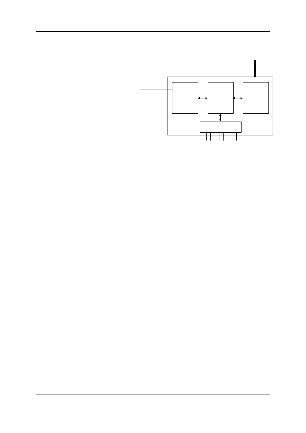
•The radio port allows the 105G to
communicate with other 105G
and/or 105U modules using the
105U protocol (called “ELPRO
105U”). Messages from the 105U
modules are received by the radio
port and used to update the input
values in the 105G database. The
radio port also creates the correct
radio message to set outputs on the
remote 105U modules.
The ELPRO 105U protocol is an
extremely efficient protocol for
radio communications. Radio
messages can be sent using exception reporting - that is, when there is a change of an
input signal - or by read/write messages. Each message can comprise a single I/O value,
or multiple I/O values (termed a “block” of I/O). There are also update messages, which
are sent for integrity purposes. Messages include error checking, with the destination
address sending a return acknowledgement. Up to five attempts are made to transmit the
message if an acknowledgement is not received. The ELPRO 105U protocol is designed to
provide reliable radio communications on an open licence-free radio channel.
•The Data-Bus port enables communications between a host device, which could be a PLC,
DCS, HMI, intelligent transducer, or an actual data-bus), and the 105G database. A “host
device” may be several devices connected to a data-bus (for example, an Ethernet LAN) -
in this manual, the LAN is considered as a “host device”.
The data-bus port decodes messages from the host device and reads or writes I/O values to the
database. The data-bus port can also generate messages to the host device.
The 105G database effectively isolates the data-bus and the radio network. This provides a
high level of system performance. The 105U radio protocol is very efficient and reliable for
radio communications. It minimises radio channel usage by "change-of-state" reporting, and
allows the use of intermediate repeater addresses. It also allows peer-to-peer (105U to 105U,
105G to 105G) and peer-to-master (105U to 105G) communications. PLC protocols, by
comparison, are designed to provide transfer of large I/O files by "wire" link. The 105G
retains the advantage of both protocols in their respective communications media.
1.2.1 On-board I/O
The 105G has eight on-board discrete I/O. Each I/O point can be used as either a discrete
input (voltage free contact input) or discrete output (transistor output) - an I/O point cannot
be used as both input and output. Each I/O point is linked to two separate registers I/O
registers in the database - one for the “input” function and one for the “output” function.. If
the output register is set “on” by the data bus or by a radio message from a remote module,
then the 105G will automatically set the input register for the same I/O point to “off”.
The 105G also has three internal inputs linked to I/O registers:
♦Supply voltage status - if the normal supply fails, this status is set on.
DATA BUS
INTERFACE
DATA BUS
PROFIBUS
ETHERNET
MODBUS
DFI
RADIO
PORT
I/O
DATABASE
905U
RADIO
INTERFACE
105U-G
ON-BOARD I/O
EIGHT DISCRETE I/O SIGNALS

105U-G Wireless Gateway User Manual
Page 11 © August 2003
♦Low battery voltage. The 105G has an internal battery charger to trickle charge a back-
up battery. If the battery voltage is low, this status is set.
♦Battery voltage - the actual value of the connected battery voltage.
1.3 The Wireless Network
The 105G can communicate with up to 490 other addresses - this could be 490 other 105U
modules, or in the case of 105K modules, it could be many thousands of modules (as many
105K modules can share the same address). 105G modules may take up more than one
address under some circumstances.
Any 105G or 105U module can act as a radio repeater for other modules - that is, radio
messages can be passed onto other modules. Up to five repeater addresses can be configured
for messages transmitted to a 105G module.
Each module can have a unit address between 1 – 95, but the 105G also recognises repeater
addresses in conjunction with the unit address as the module “identifier”. Hence module #2 is
recognised as different to #2 via #57 - #57 being a repeater.
1.3.1 105U to 105G Network
In the wireless I/O system, the 105G acts as a normal 105U module (this covers 105U I/O,
105S I/O, 505U and 105U-C modules).
105U modules transmit messages to the 105G address and the 105G acknowledges these
messages like a normal 105U module. When a 105G transmits messages to change remote
outputs, it will "re-try" if it does not receive an acknowledgement, like a normal 105U
module.
Remote 105U modules can connect to 105S modules in the normal way. The 105G host can
access I/O on 105S modules by using the intermediate 105U as a repeater. 105S modules
cannot connect directly to a 105G module.
105U modules can transmit input
messages directly to outputs on other
105U module, as well as the 105G. The
same input can be transmitted to
different addresses by entering two
"mapping" configurations at the remote
module.
Normal 105U Messages
I/O registers in a 105G can be
configured (mapped) to outputs at
remote 105U modules, or I/O registers
in 105G modules. The 105G will transmit an I/O message when a “change-of-state” occurs
for that I/O register . Registers have a configurable “sensitivity” value - this determines how
much the register value has to change to trigger a change message. A change-of-state occurs
when the register value has changed by more than the sensitivity value since the last
transmission.
The 105G also transmits periodic update messages if there has been no change - if an I/O
register is mapped to a remote output or another 105G, then that register can be configured
with an update time.
105U-G
105U-3
105U-1 105S-2
505U

Chapter One Introduction
MAN_105G_1.5 Page 12
105G modules can transmit to 105G modules as well as other 105G modules. There can be
multiple 105G and 105C modules in a network - as well as 105U I/O. Because the 105U
protocol is peer-to-peer, there are few constraints on communications between multiple 105U
modules.
Poll Messages
A 105G can also generate poll messages to remote 105U modules. These poll messages act in
the same way as a start-up poll - the remote module immediately responds with update
messages for any I/O mappings configured to the 105G.
Poll messages can be triggered by:
♦time period, configurable 1 – 4096 sec (1.1 hour), or
♦real time clock, or
♦on demand by the host device, by writing to a “trigger register” in the 105G
1.3.2 105G to 105G Network
Different types of 105G modules can communicate - for example, a Modbus 105G can
communicate with an Ethernet 105G. I/O registers in one 105G can be transmitted to I/O
registers in another 105G. When the 105G is configured, “mappings” can be entered linking
I/O registers to registers in another 105G.
As well as the normal “I/O change” messages and update messages, the 105G has “block
read” and “block write” messages for use with other 105G modules. These messages will
transmit multiple register values instead of only one as in the normal 105U message. The
block read/write messages increase the efficiency of radio communications where a 105G
“sees” a large number of changes in its database at the one time. For example, if a host writes
a block of 100 signal values to a 105G, and 20 of these values have changed since the last
write-operation. If the block is mapped to another 105G, then the 105G can transmit all 20
values in one radio message, instead of 20 messages.
Normal I/O messages can be repeated by any type of 105U I/O module, however block
read/write messages can only be repeated by other 105G modules.
Block Read Message
A block read message is a request to another 105G to transmit the values of a consecutive
block of registers. The destination 105G will respond with the values, which will be stored in
a corresponding block of registers in the originating 105G. A block read message can be
triggered by:
♦time period, configurable 1 – 4096 sec (1.1 hour), or
105U-G
105U-3
105U-1
PLC
105U-C
PLC

105U-G Wireless Gateway User Manual
Page 13 © August 2003
♦real time clock, or
♦on demand by the host device, by writing to a “trigger register” in the 105G.
Block Write Message
A block write message transmits a consecutive block of register values from one 105G to a
destination 105G. It can be triggered by:
♦time period, configurable 1 – 4096 sec (1.1 hour), or
♦real time clock, or
♦on demand by the host device, by writing to a “trigger register” in the 105G, or
♦a change-of-state event occurring within the block of I/O registers.
If a block write message has been configured to be transmitted on change-of-state, a “time
window” is configured. When a change-of-state occurs in one of the registers in the block,
the time window will be activated. All changes during the time window will be grouped
together and transmitted as one block write message. That is, the block write message will
not be sent immediately the first change-of-state occurs (unless the time window is configured
to zero), but will be sent at the end of the time window - any other registers in the block that
change during the time window will be sent as part of the same message. The time window
can be configured from 0 – 255 seconds.
1.3.3 “Data Concentrator” Networks
105G units can act as “data concentrator” units to collect I/O from a local network of 105U
wireless I/O modules and pass the I/O on to another 105G as a block.
This type of network reduces the amount of radio traffic and is suitable for systems with a
large number of I/O modules. The system is divided into local sub-networks, each with a
105G unit. The 105U modules transmit their I/O vlaues to the 105G. The 105G then
transfers these values to the “central” 105G using a block transfer which is very efficient
compared to a lot of individual I/O transmissions.
The data concentrator network is different than using the 105G as a repeater. A repeater re-
transmits each message in the same format. A data concentrator collects the I/O values as a
block, and transmits the complete block in one transmission.
TO HOST
DEVICE
NETWORK OF
105U I/O UNITS
105U-G
105U-G
NETWORK OF
105U I/O UNITS
105U-G

Chapter Two Operation
MAN_105G_1.5 Page 14
Chapter 2 OPERATION
2.1 Start-up
The 105G operating software and the database configuration are stored in non-volatile
memory, however the database I/O register values are lost on power failure (in the same way
as a PLC).
On start-up, the 105G sends "start-up poll" messages to remote modules based on the source
address of inputs configured in the database (the start-up messages can be disabled by
configuration). The remote modules respond with update messages for their inputs, which
sets initial values in the 105G I/O database registers. The 105G provides a delay of 5 seconds
between each start-up poll, to allow the remote module to respond and to avoid overloading
the radio channel.
If there are a lot of remote modules, then this start-up stage may take a significant time, and
this should be allowed for in the system design. The 105G has an internal battery charger
feature and the use of a back-up battery should be considered if this start-up delay presents a
constraint to system reliability. Start-up polls may be disabled for individual remote modules
in the database configuration.
For the host device, the 105G provides an "Active" signal on the RS232 port (DCD pin 1). Its
purpose is to indicate to the host that the 105G is now processing output messages for the
remote modules. When the 105G powers down (or should an internal fault occur), the
"Active" signal resets (turn “off” or “0”). When the 105G starts-up, it holds the "Active"
signal in a reset condition (“off” or “0”) for a time equal to the number of remote addresses
(or modules) configured times 5 seconds plus any delay if remote addresses are offline. For
example, if there are 20 remote addresses configured in the 105G database, then the “active”
signal will be held in the reset state for 100 seconds (20 x 5). During this period, the 105G
will not change any output values in its database. After this time, the 105G will set the
"Active" signal (to “on” or “1”) - the host can then send messages to the 105G to update the
output values in the database.
2.2 Operation
The 105G database can hold values for 4300 I/O signals plus the 8 on-board I/O. The
database registers (also called I/O registers) can be accessed by both the radio port and the
data bus port. The host device can change values in the database via the data bus, and the
105G can transmit radio messages out with the new values. Radio messages can be received
with new values for database registers, and these new values can be written to the host device
or read by the host device, via the data bus.
The 105G operation must be configured before the 105G will function. Configuration is
achieved by creating a configuration file on a PC and downloading this file to the 105G. The
105G configuration may also be "uploaded" to a PC for viewing and modification. For more
information, refer to the Configuration section of this document.
Each I/O register in the 105G database has a 16-bit value. It doesn’t matter if the remote I/O
is digital (discrete), analogue or pulse. The host protocol driver in the 105G will convert the
16 bit value into a value that the host will understand. For example, if the host device

105U-G Wireless Gateway User Manual
Page 15 © August 2003
requests a binary/digital read command, the 105G will convert the 16 bit value into a binary
(1 bit) value before it responds.
An example of normal operation - assume that a remote module has address 14 and the 105G
is address 1. Module #14 is configured with a mapping DI1 →I/O Reg 76 at #1. When DI1
turns "on", module #14 transmits a message. If the 105G can hear this message, it will
transmit an acknowledgement back to module #14, and updates the value of I/O register 76 in
the 105G database. The host device can read I/O register 76 via the data-bus, or the 105G
may write the value of I/O register 76 to the host device.
I/O registers that receive values from other 105U or G modules via radio are configured with
a “Communications fail time”. If the 105G does not receive a message for this I/O register
within the comms-fail time, then the I/O register is given a “comms fail” status which the host
device can read.
I/O registers that transmit out to other 105U or G modules are configured with an “update
time” and a “sensitivity”. The 105G will transmit a message to the configured remote output
whenever the I/O register value changes by the sensitivity amount – if it has not changed
within the update time, the 105G will send a message anyway. The 105G will make five
attempts to send a message - if it does not receive an acknowledgement from the remote
module, then the I/O register is given a “comms fail” status which the host device can read.
Each I/O register has an associated “status” register, which includes information such as
comms-fail status. As well as each I/O register having an individual comms-fail status, each
remote module has an overall comms fail status. This status is “set” (on) whenever a comms-
fail occurs for an individual I/O register, and is “reset” (off) whenever a message is received
from the remote module. The 105G can be configured to not send any update messages to a
remote module if it senses that the remote module is in “comms fail” - that is, if any I/O
register associated with the remote module is in “comms fail”. It will start sending update
messages again when the 105G receives a message from the remote module. The default
configuration is that output updates ARE sent during comms fail conditions.
905U-G
905U-1
DIN1
#14 #1

Chapter Two Operation
MAN_105G_1.5 Page 16
2.3 Database
The 105G database has 10 000 registers, each of 16 bit size. The structure of the database is:
Registers Purpose
0 - 4299 I/O registers
4300 - 4399 On-board I/O
4401 - 4495 Comms-fail status and radio strengths for remote modules
4496 – 4999 Spare - General use
5000 - 9399 Status registers - 16 bit status for each I/O signal
9400 – 9500 Spare – General use
9500 - 9999 Status registers for block read/write messages
The register numbers may be used by the Host Protocol Driver to access I/O values and I/O
status information. Each configured I/O point has a 16 bit value (in registers 0000 - 4299),
and a 16 bit status value. The status register is located at 5000 plus the I/O value register. For
example, an I/O point in register number 2560 has a status value in register number 7560
(5000 + 2560).
Details of the status register are provided in Appendix A. The most important part of the
status register is the 15th or most significant bit - this indicates comm-fail status for the I/O
register. If the most significant bit is set, then the I/O register is in comms-fail.
The host device can read the status registers. For example, the communications status of an
output configured at register number 3001 can be examined by reading register number 8001
(5000 + 3001). If the register value is greater than 32767, then the 15th bit is set, indicating
that the output has a communications failure.
2.3.1 On-board I/O and Internal I/O
The 105G has eight discrete I/O points. These may be used as inputs or as outputs. Inputs are
linked to registers 4300-4307. That is, if a contact connected to DIO1 is “on”, then register
4300 is given an “on” value. Outputs are controlled from registers 4320-4327; that is, if
register 4327 is set to an “on” value, then output DIO8 is activated.
Whenever an output register is set “on”, the corresponding input register is automatically set
“off”. For example, if register 4321 is set to “1”, the 105G will also set 4301 to “0”. This
means that if both the input and output registers corresponding to the same I/O point are used
in the configuration, then the output register has priority.
Outputs may be written to by either the host device or by a remote 105U via the radio port.
Input values can be sent to the host device or to a remote module via the radio port.
The 105G also monitors its battery voltage and supply voltage. These are stored in registers
4310 and 4311 respectively, as 16 bit values, scaled so that a value of 16384 decimal (hex
4000) corresponds to 8 V, and a value of 49152 (hex C000) corresponds to 40V.
A low battery alarm is available at register 4308. This becomes active when the battery
voltage falls below 11.3V, and clears when the battery voltage rises above 11.8V. Supply
voltage is also monitored, and an alarm is available at register 4309. This becomes active if
the supply voltage falls below 8.0V, and clears when the supply voltage rises above 9.0V.

105U-G Wireless Gateway User Manual
Page 17 © August 2003
I/O Register Description
4300 Input value DIO 1
4301 Input value DIO 2
4302 Input value DIO 3
4303 Input value DIO 4
4304 Input value DIO 5
4305 Input value DIO 6
4306 Input value DIO 7
4307 Input value DIO 8
4308 Low battery voltage status
4309 Supply voltage fail status
4310 Battery voltage value
4311 Supply voltage value
I/O Register Description
4320 Output value DIO 1
4321 Output value DIO 2
4322 Output value DIO 3
4323 Output value DIO 4
4324 Output value DIO 5
4325 Output value DIO 6
4326 Output value DIO 7
4327 Output value DIO 8
2.4 The Host - 105G Link
For the host device, the 105G "looks" like a PLC (or a "virtual PLC"), containing the I/O for
the complete wireless I/O system.
DATABASE
I/O
"VIRTUAL PLC"
DATA-BUS
“HOST DEVICE” 105U-G

Chapter Two Operation
MAN_105G_1.5 Page 18
2.4.1 Modbus / DF1
The user selects whether the 105U-G-MD1 should act as a Modbus Master or Modbus Slave
or DF1 device.
The data type and baud rate of the serial communications must be configured at the 105G to
match the host. Data types can be 7 or 8 bit, even/odd/no parity, with 1 or 2 stop bits. Data
rates can be 300 - 19200 baud.
The full 105G database (4300 registers) can be accessed by the Host Device.
2.4.2 Profibus
The Profibus port has auto-detect of baud rate from 9600 bits/sec to 12Mbit/sec - no
configuration is required. A Profibus slave address must be entered (1 – 126).
The Profibus port cannot access the full 105G database. The 105U-G-PF1 Profibus unit has
an internal HMS Anybus board to provide the Profibus interface. The Profibus port (that is,
the “host device”) communicates with the HMS board which communicates with the 105G
database. Links are configured linking the database I/O registers and the HMS Profibus I/O
bytes.
The HMS module provides a total of 416 I/O bytes, with a maximum 244 input bytes and
maximum 244 output bytes. A Profibus byte can contain 8 discrete (binary) values, or two
bytes can be used for a 16-bit analogue or pulse register. So the HMS Profibus interface is
limited to 1952 discrete inputs or 122 analogue inputs or a combination. The same applies for
outputs.
For example, a Profibus host wants to read 800 discrete inputs (100 bytes) and write 400
discrete outputs (50 bytes). This will take up 150 bytes of the HMS interface, leaving 266
left. The remaining bytes could be used for 133 analogue I/O - up to 72 analogue inputs
(244 – 100 discrete input bytes) plus 61 analogue outputs - or vice-versa.
2.4.3 Ethernet
The Ethernet port automatically handles Ethernet communications at 10 or 100 Mbit/sec. A
device IP address is entered so that other Ethernet devices can recognise the 105G.
The Ethernet port cannot access the full 105G database. The 105U-G-ET1 Ethernet unit has
an internal HMS Anybus board to provide the Ethernet interface. The Ethernet port (that is,
the “host device”) communicates with the HMS board which communicates with the 105G
database. “Data bus links” are configured between the database I/O registers and the HMS
Ethernet I/O bytes.
The HMS module provides a total of 2048 input bytes and 2048 output bytes. A Ethernet
byte can contain 8 discrete (binary) values, or two bytes can be used for a 16-bit analogue or
pulse register. So the HMS Ethernet interface is limited to 4300 discrete inputs (the limit of
the 105G database) or 1024 analogue inputs (the limit of the HMS interface) or a
combination. The same applies for outputs.
For example, an Ethernet host wants to read 500 analogue inputs (1000 bytes). The
remaining input bytes (1548) could be used for 12,384 discrete inputs - but the 105G
database is not this big. Provided there are no outputs required, there could be 3800 discrete
inputs (4300 – 500 analogues). If there are outputs required, then the number of discrete
inputs available will be further limited.

105U-G Wireless Gateway User Manual
Page 19 © August 2003
2.5 Radio System Design
Each wireless I/O system can have up to 95 unit addresses, although up to 255 505U module
can share the same unit address (refer to 505U User Manual).
Each 105U module can have up to 31 x 105S modules connected to it. These modules are
addressed 96 - 127. More than one 105S module can have the same address, provided they
are not connected to the same 105U module - that is, #100 via #16 is identified as a different
module to #100 via #65.
A constraint that needs to be considered is the capacity of the radio channel. If there is too
much traffic on the radio channel, then the system quickly becomes unreliable. The
recommended maximum average traffic density is 40 messages per minute provided all radio
paths are reliable. If there are marginal radio paths, resulting in re-tries of transmitted
messages, then the maximum traffic density is reduced considerably. Each block read/write
messages should be counted as two messages because of the length of these messages.
A 105G can be used as a repeater module for messages between other modules.
2.5.1 Radio Signal Strength
The 105G records the radio signal strength of remote modules that communicate directly (that
is, not via repeaters). There are 95 database registers (4401 – 4495) which store the radio
strengths – corresponding to remote addresses #1 - #95. The radio strength (RSSI) is
measured in dBm (relative to 1mW of RF power). The RSSI value is stored in the 8 least
significant bits of each register - a value of –84 dBm would be stored as decimal 84.
These database registers will hold the strength of the last message received from the address.
If a message is received from a remote module via a repeater, then the measurement is
recorded in the address of the last repeater. For example, if a message is received from #24
directly, then the RSSI will be recorded in register 4424. If a message is received from #24
via #25, then the RSSI is recorded in register 4425. The 105G will not know what the radio
strength of the message from #24 to #25 is. If #25 is another 105G, then it can record this
RSSI and this register could be mapped to an I/O register in the first 105G.
These RSSI registers can be read by the host device as well as being mapped to I/O registers
in other 105G modules.
The first half of the register (8 most significant bits) will be decimal 0 (hex 00) if the remote
module has active communications. If a comms fail status to this address occurs, the most
significant bit will be set. For example, if the last message received from #38 is –99dBm,
then the 16 bit value of register 4438 will be decimal 99 or hex 0063. If the “comms fail”
status for #38 is set, the 16 bit value of register 4438 will become decimal 32,867 (32768 +
99) or hex 8063.
2.5.2 Repeaters
Radio paths may be extended by using intermediate modules as repeaters. A repeater will
receive and re-transmit the radio message. Up to five repeater addresses can be configured -
that is, a radio message can pass through five intermediate modules. For normal I/O
messages, any 105U module (except 505U modules) can be used as a repeater, however for
block read/write messages, only 105G modules can act as repeaters.

Chapter Two Operation
MAN_105G_1.5 Page 20
2.6 Radio Comms Failure
The 105G has an internal "communications failure" (comms fail) status for each I/O point in
its database. There is also a comms fail status for each module with direct communications -
see 2.5.1 above.
For I/O registers which are mapped to a remote output or another 105G, the comms fail status
is set if the 105G does not receive an acknowledgement for a message being sent to that
remote output. The comms fail status resets when a successful transmission occurs.
For I/O registers which have been mapped , from a remote input or another 105G, a comms
fail time period may be configured. If a radio message for this I/O register has not been
received within this time, then this registers comms fail status is set. The comms fail status
will reset when a message is received for this register. If the comms fail time is configured as
zero, then the comms fail status will never be activated.
The communications failure status is bit 15 of the status register for each I/O point. If the
host device reads a register as a digital or binary value, then the 105G returns bit 15 of the
register (0 or 1) - this is the comms fail bit of a status register.
It is important to use the comms fail status in the overall system design, as any system can
fail.
The 105G also provides an additional comms failure feature to stop the 105G transmitting
output messages to an individual remote address if the 105G already knows that this remote
address is in communication failure. This prevents the 105G from congesting the radio
channel with a lot of unnecessary transmissions (and re-transmissions). This function is
called "Don’t Send if In Comm Fail" and is configurable by the user for each individual
remote address. The 105G retains a "remote address comms fail" status for the remote
addresses configured for this function. If any output with this remote address goes into
communications failure, then the remote address comms fail status is set ("on" or 1) - every
time an input with this remote address receives a radio message, then the remote address
comms fail status is reset ("off" or 0). While the remote address comms fail status is set, the
105G disables any output messages being sent to this remote address.
When this feature is configured, all output transmissions are stopped if communications with
a remote module fails for a short period. They will start again when an input message from
this module is received. If the 105G determines that a output message should be sent to an
output which is disabled because of this feature, then the output message will not be sent and
the comms fail status of that output is set ("on" or 1).
If it is desired to use this function with a remote 105U module, but there are no inputs from
this module being used, then it is easy to configure an unused input or an internal input (mains
fail or low battery voltage etc). It is the comms fail status for the input, which is used, not the
input itself.
2.6.1 Monitoring Communications Failure
The host device can monitor the communications status of an I/O point by reading the status
register for this point as a binary/discrete register. Modbus, and many other protocols, will
convert a 16 bit register value to a binary/discrete value by returning the most significant bit -
for the status register, this corresponds to the comms status bit.
Other manuals for 105U
1
This manual suits for next models
1
Table of contents
Other ELPRO Gateway manuals