Page 8 of 17 man_A-ERTK-A2_V1.3.docx
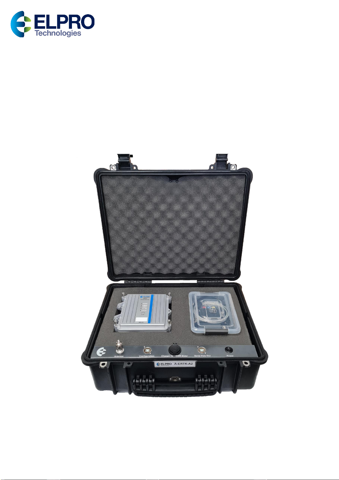
ERT-A2 ERRTS Decoder
Description
The ERT-A2 will receive and decode ALERT (version 1) or ALERT2 radio messages and translate
the radio messages into a serial format RS485 to USB Serial converter suitable for the portable
computer.
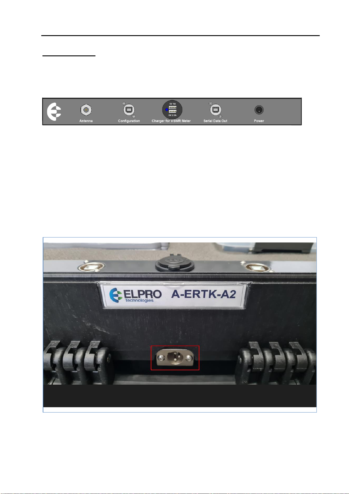
Operation
The Decoder operation is provided from a standard ERT-A2 ALERT2
cannister which is configured as a Base Receiver.
The ERT-A2 is powered internally from a Li-on battery which can be
charged via the charging port and plug-pack power supply provided in the
kit.
The power switch on the front panel turns off the ERT-A2 and isolates the
battery from drawing any further current, i.e. via the USB charging socket.
If you need to change the battery or remove it for whatever reason, please disconnect from the
connector behind the stainless-steel bracket inside the ERT-A2 as shown in the diagram above.
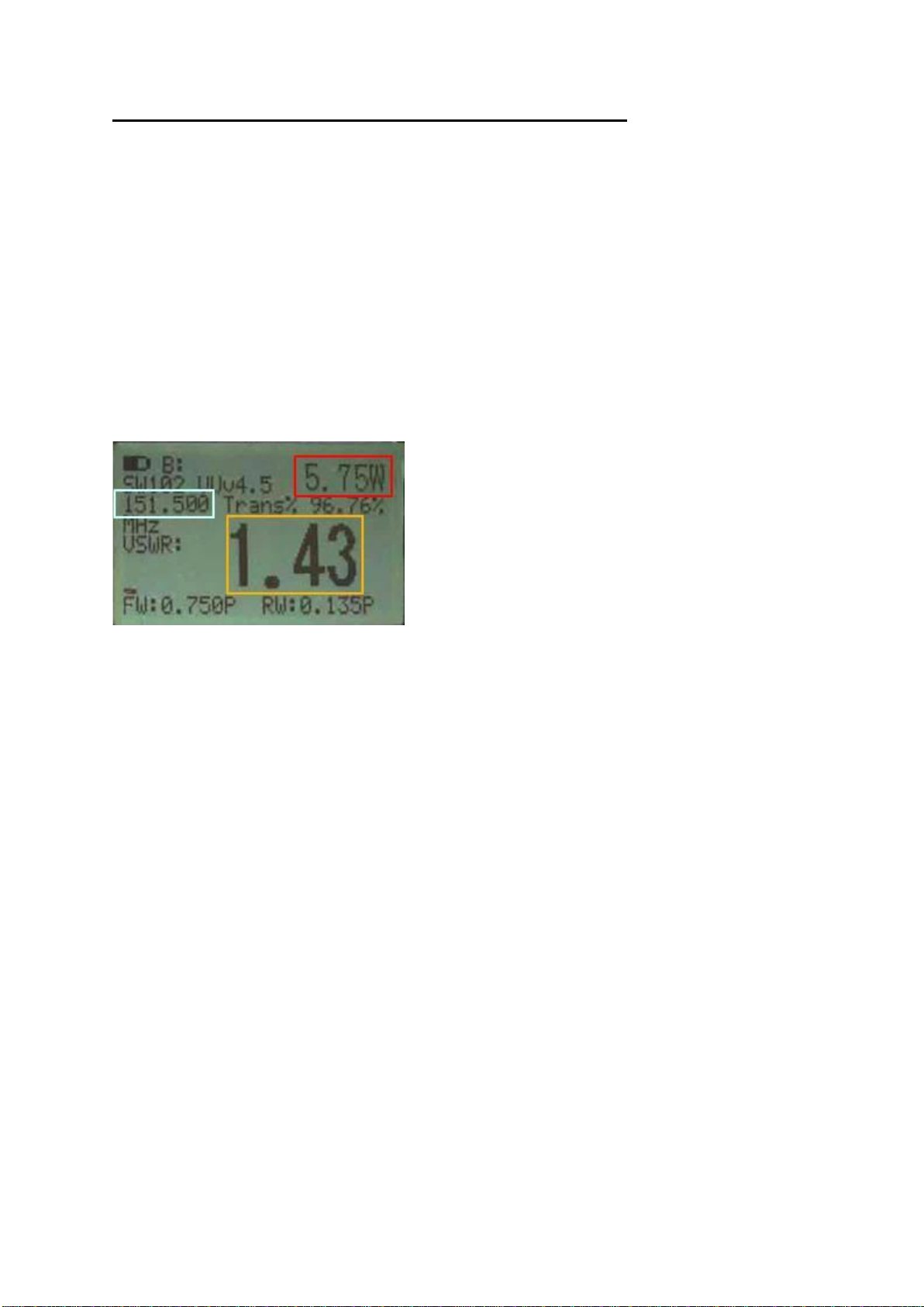
Configuration
As the Receive/Decoder is a standard ERT-A2 it can be used as a spare Field station or Repeater if
required in an emergency and so may need to be reconfigured from time to time.
To reconfigure the unit back to a Base Receiver, connect to the “configuration” USB B Socket
in the case using a standard USB A USB B (Printer) cable (included) and follow the basic
configuration requirements as per below.
From a factory defaulted unit select “Unit Config” from the main menu then “Communication”
Configuration Mode = “Integrated Radio Reporting”
Unit Type = “Base Station Rcvr”
Tx Frequency = Configure to match your system.
RX Frequency = Configure to match your system.
Report Format = Generally this would be ALERT Binary which receives both ALERT Binary
and ALERT IFLOWS format. If your network operates using ALERT2 protocol, select this from
the menu.
Next, navigate back to the main menu and then select “Show/Save configuration”, check its
correct then select “Yes” to save.