ELREHA BMT 2101 User manual

Betriebsanleitung 5311249-00/04
Operating instructions
Notice d‘utilisation
Temperatur-Messmodul
Temperature Measuring Module
Régulateur d'acquisition température
BMT 2101
ELEKTRONISCHE REGELUNGEN GMBH
SoftwVers. 1.06
Kurzbeschreibung
• Temperaturfühler-
modul im
AP-Gehäuse
• Anschluss für
4x TF 201oder
4x TF 501-Fühler
• 1 virtueller Fühler
• Parametrierbar und
auslesbar über RS-
485-Schnittstelle
• Optionales Warn-
relais für die Weiter-
leitung von Über-/
Untertemperatur-
warnungen bzw.
Fühlerstörungen
• Interne Diagnose
LEDs
• Entwickelt zur
Erweiterung von
Reglernetzwerken
um weitere Fühler-
eingänge oder zum
Aufbau umfang-
reicher Protokollier-
systeme mit SMZ-
Frontends
Brief Description
• Temperature Sensor
Module for wall
mounting
• Connection for
4x TF 201 or
4x TF 501-sensors
• 1 virtual sensor
• Can be programmed
and read via
RS-485-interface
• Optional alarm relay
allows forwarding of
error messages like
temperature too high/
low, sensor malfunc-
tion
• Internal diagnostic
LEDs
• Designed to extend
controller networks
by additional sensor
inputs or to set up
large data logger
systems using SMZ
Frontends
Description
• Boîtier d'acquisition
pour montage mural
• Connexions pour
4 sondes de
température type
TF 201 ou
TF 501 (PT1000)
• 1 sonde virtuelle
• Lecture et paramé-
trage via interface
RS-485
• Relais d'alarme en
option pour trans-
mission défauts de
température ou de
sonde
• Diagnostique
interne par LED
• Prévu pour aug-
menter l'acquisition
de points de mesure
dans un réseau de
régulateurs existant
ou pour créer un
système
d'enregistrement et
surveillance complet
avec le SMZ en tête.
Anwendungsbeispiel - Application Example - Exemple d'application
Über Schnittstelle les-/einstellbare Parameter
Istwert 1-4....................................-100,0°C...+100.0°C
Auflösung .............................................................0,1K
Programmversion.................................z.B. BMT 1.06
Fühlertyp.................[TF501] (Pt1000) / TF 201 (PTC)
Gerätename........................max. 16 Zeichen ["BMT"]
Parameter je Fühler
Fühler ............................................................[ein] / aus
Gewichtung Fühler 1..........................0...100 % [0 %]
Gewichtung Fühler 2..........................0...100 % [0 %]
Gewichtung Fühler 3..........................0...100 % [0 %]
Gewichtung Fühler 4..........................0...100 % [0 %]
Warngrenze unten.....................± 100.0°C [-100,0°C]
Warngrenze oben.....................± 100,0°C [+100.0°C]
Warnverzögerung..........................0...240 min [5 min]
Istwertkorrektur.....................................± 10,0K [0,0K]
Fühlername.................. max. 16 Zeichen ["sensor x"]
Werte in Klammern [...]
= Werkseinstellungen
Parameters, readable/programmable via interface
Act. Temperature 1-4..................-100,0°C...+100.0°C
Resolution ............................................................0,1K
Program Version...................................e.g. BMT 1.06
Sensor Type...........[TF501] (Pt1000) / TF 201 (PTC)
Unit Name...................... max. 16 characters ["BMT"]
Parameters of each Sensor
Sensor .............................................................[on] / off
Emphasis for virtual sensor 1 ............ 0...100 % [0 %]
Emphasis for virtual sensor 2 ............ 0...100 % [0 %]
Emphasis for virtual sensor 3 ............ 0...100 % [0 %]
Emphasis for virtual sensor 4 ............ 0...100 % [0 %]
Lower Alarm Limit......................± 100.0°C [-100,0°C]
Upper Alarm Limit.....................± 100.0°C [+100.0°C]
Alarm Delay....................................0...240 min [5 min]
Sensor Correction.................................± 10,0K [0,0K]
Sensor Name........... max. 16 characters ["sensor x"]
Values in brackets [...]
= Factory Settings
Paramètres interrogeables/réglables via RS-485
Mesure 1-4..................................-100,0°C...+100.0°C
Résolution .............................................................0,1K
Version programme...............................ex. BMT 1.06
Type de sonde......[TF 501] (Pt1000) / TF 201 (PTC)
Nom de l'appareil...........16 caractères maxi. ["BMT"]
Paramètrage pour chaque sonde
Sonde connectée ........................................[oui] / non
Accentuation pour le capteur virtuel1 0..100 % [0 %]
Accentuation pour le capteur virtuel2 0..100 % [0 %]
Accentuation pour le capteur virtuel3 0..100 % [0 %]
Accentuation pour le capteur virtuel4 0..100 % [0 %]
Alarme basse.............................± 100.0°C [-100,0°C]
Alarme haute.............................± 100.0°C [+100,0°C]
Retard d'alarme .............................0...240 min [5 min]
Correction..............................................± 10,0K [0,0K]
Nom de sonde.........16 caractères maxi. ["sensor x"]
[...] sont les valeurs réglées en usine.
Hinweis Notice AVIS
DO
BM T 2101
D a ta b us (R S - 48 5, E -L in k )
BM T 2101
GND
NDO
DO
NDO
GND
NDO
BM T 2101
DO
GND
Virtuelle Fühler
Es können bis zu 4 Fühler zu einem „virtuellen“ Füh-
ler zusammengefasst werden, was eine Mittelwert-
bildung mit einstellbarer Gewichtung ermöglicht.
Die Summe aller eingestellten Gewichtungswerte
muss 0 % oder 100 % betragen, andernfalls wird ein
Zuordnungsfehler generiert.
Stehen alle Gewichtungen auf 0 % so ist der virtuelle
Fühler abgeschaltet.
Die Defaultwerte sind so gewählt, dass der virtuelle
Fühler ausgeschaltet ist.
Parameter
Fühlername.......................................max. 16 Zeichen
Warngrenze unten.....................± 100.0°C [-100,0°C]
Warngrenze oben.....................± 100,0°C [+100.0°C]
Warnverzögerung..........................0...240 min [5 min]
Fehlermeldungen
- Fühlerbruch-/kurzschluss 1-4
- Untertemperaturwarnungen 1-4, virtueller Fühler
- Übertemperaturwarnungen 1-4, virtueller Fühler
- Zuordnungsfehler virtueller Fühler
Virtual Sensors
Up to 4 sensors can be combined to form a
„virtual“ sensor, which allows averaging with
adjustable weighting.
The sum of all set weighting values must be 0% or
100%, otherwise an assignment error will be
generated. If all weights are set to 0%, the virtual
sensor is switched off.
With default settings, the virtual sensor is switched
off.
Parameters
Sensor Name............................... max. 16 characters
Lower Alarm Limit......................± 100.0°C [-100,0°C]
Upper Alarm Limit.....................± 100.0°C [+100.0°C]
Alarm Delay....................................0...240 min [5 min]
Error Messages
- Sensor break / short circuit 1-4
- Low temperature alarm 1-4, virtual sensor
- Overtemperature alarm 1-4, virtual sensor
- Assignment error virtual sensor
Sondes Virtuelles
Jusqu‘à 4 sondes de température peuvent être
combinées pour former une „sonde virtuelle“ :
cette fonction permet de réaliser des moyennes de
température en fonction de l‘influence de chaque
sonde (réglable). La somme de toutes les
influences doit être égale à 0% ou 100%. Dans le
cas contraire, une erreur d‘attribution sera générée.
Si toutes les influences sont paramétrées sur ‚0%‘,
la sonde virtuelle sera désactivée. La „sonde
virtuelle“ est désactivée par défaut (réglage d‘usine).
Paramètres
Nom de sonde.............................16 caractères maxi.
Alarme basse.............................± 100.0°C [-100,0°C]
Alarme haute.............................± 100.0°C [+100,0°C]
Retard d'alarme .............................0...240 min [5 min]
Messages d'erreur
- Coupure sonde / Court-circuit sonde 1-4
- Alarme basse température 1-4, sonde virtuelle
- Alarme haute température 1-4, sonde virtuelle
- Erreur d‘attribution sonde virtuelle

Seite / Page 2 Betriebsanleitung / Technical Manual BMT 2101
13
S2
230VAC
230VAC
1 2 3 4 105 6 11 12
alarm
L PEN
BMT 2101
S1
161514 2017 2321 22 24
RS-485
S3
DO
S4
CANL
NDO
GND
CANH
Anschlussklemmen und Adress-Schalter /
Positions of screw terminals and address switches /
Connexions et interrupteurs d'adressage
Elektrischer Anschluss /
Electrical Connection /
Connexions électriques
Setting an address in a controller network
Address switch x 10 switch x 1
0 0 0
1 0 1
2 0 2
3 0 3
4 0 4
.
.
10 1 0
11 1 1
12 1 2
and so on. The highest usable address is '77'
Abmessungen / Dimensions
Befestigungsbohrungen /
Mounting holes /
Fixation mural
Adresseinstellung /
Address setting /
Réglage de l'adresse
Interne LEDs /
Internals LEDs /
LED internes
L1: Leuchtet wenn Relais
angezogen
Permanent ON if relay is
activated
s'allume si le relais d'alarme est
enclenché
L2: Blinkt bei Betrieb
Flashes while normal operation
clignote si en marche
L3: Blinkt bei Datenübertragung
Flashes while data
transmission
clignote si transmission
données RS-485
L4: nicht verwendet /
not used
non-utilisé
5x PG13
110 mm (4.33 inch)
110 mm (4.33 inch)
110 mm (4.33 inch)
67 mm (2.64 inch)
95 mm (3.74 inch)
95 mm (3.74 inch)
Protective Earth
Earth
Schutzleiteranschluss
Anschluss für Erde
1 2 3
4
L1
5 6
5
4
5
6
6
4
23
20
22
21
24
16
9
address
x 10 x 1
1
0
7
8
9
2
3
7
8
0
1
2
3
L3
L4
L2 1 0 1 1 1 2 1 3 1 4 15 17
12 3
4
L1
5 6
5
4
5
6
6
4
23
20
22
21
24
16
9
address
x 10 x 1
1
0
7
8
9
2
3
7
8
0
1
2
3
L3
L4
L2 1 0 1 1 1 2 13 1 4 1 5 17
L2
L3
L4

Betriebsanleitung / Technical Manual BMT 2101 Seite / Page 3
Vernetzungsbeispiel mit SMZ 5140 (vereinfacht)
• Verbindung mit handelsüblichem Datenkabel
• Jedes vernetzte Modul/Regler erhält eine
individuelle Adresse
• Abschirmungen und Erdverbindungen sind auf
kürzestem Weg zur nächsten Erdklemme zu
führen
• Der nicht abgeschirmte Teil des Datenkabels
muss möglichst kurz sein
Network Example with an SMZ 5140 (simplified)
• Use standard data cable for the data bus
• Each connected module/controller unit gets an
individual address
• Connect shieldings and shown ground
terminals of the unit to the nearest ground
terminal in the cabinet
• The unshielded part of the data cable must be
as short as possible
Exemple de connexion avec SMZ 5140 (simplifié)
• Connexion avec un câble standard
• Chaque Module/Régulateur en réseau possède
une adresse individuelle
• Le blindage et la connexion à la terre doivent
être reliés à la borne de terre avec le moins de
longueur de câble possible
• La partie non-blindée du câble doit être la plus
courte possible
Diesen PE-Anschluss
nicht vergessen!
verdrilltes Kabel
(twisted pair)
Protective Earth
Earth
Schutzleiteranschluss
Anschluss für Erde
S3
1412
L PEN
1165 104321 13
alarm S1 S2
BMT 2101
DO
CANL
NDO
GND
CANH
242221 2317 2015 16
RS-485
S4
S3
1412
alarm
L PEN
S1
1165 104321 13
S2 RS-485
DO
S4
CANL
NDO
GND
CANH
242221 2317 2015 16
BMT 2101
S2
12
L PEN
1165 104321
alarm S1
BMT 2101
13
DO
CANL
NDO
GND
CANH
242221 2317 2014 15 16
RS-485
S3 S4
S2
12
alarm
L PEN
S1
1165 104321 13
RS-485
S3
DO
S4
CANL
NDO
GND
CANH
242221 2317 2014 15 16
BMT 2101
NDO
PC 485
46
SMZ 5140
DO 47
47
Modem 232Line 485
44
GND
45
46
OUT
44
43
CTS
RTS
NDO
GND
DO
GND
IN
41
38
37
37
38 39 40 41
40
39
4342
42
45
1 PE
2 PE
4 L
3 N
43 1
2
CANPC 232
GND
OUT
GND
H
IN
L
52
51
50
49
49
48
48 5150 52 53 54

Seite / Page 4 Betriebsanleitung / Technical Manual BMT 2101
ALLGEMEINE ANSCHLUSS- UND SICHERHEITSHINWEISE
Diese Anleitung muss dem Nutzer jederzeit zugänglich sein.
Bei Schäden, die durch unsachgemäße Handhabung oder
Nichtbeachten der Anleitung und der Sicherheitshinweise
verursachtwerden,übernehmenwirkeineHaftung!Insolchen
Fällen erlischt jeglicher Garantieanspruch.
Falls Sie Beschädigungen feststellen, so darf das Produkt
NICHT an Netzspannung angeschlossen werden!
Es besteht Lebensgefahr!
Ein sicherer Betrieb ist eventuell nicht mehr möglich wenn:
• das Gerät sichtbare Beschädigungen aufweist,
• das Gerät nicht mehr funktioniert,
• nach längerer Lagerung unter ungünstigen Bedingungen,
• starken Verschmutzungen oder Feuchtigkeit,
• nach schweren Transportbeanspruchungen.
• Die Installation und Inbetriebnahme des Gerätes darf
nur durch eine Elektrofachkraft oder unter der Auf-
sicht einer Elektrofachkraft durchgeführt werden.
• Halten Sie das Gerät bei der Montage sicher vom
Stromnetz getrennt! Stromschlaggefahr!
• Aus Gründen der Berührsicherheit darf das Gerät
nur im geschlossenen Gehäuse betrieben werden.
• Eine vorhandene PE-Klemme des Gerätes muss auf
PE gelegt werden! Stromschlaggefahr! Zusätzlich funk-
tioniert die interne Filterung von Störungen nur einge-
schränkt, fehlerhafte Anzeigen können die Folge sein.
• Das Gerät darf nur für den auf Seite 1 beschriebenen
Einsatzzweck verwendet werden.
• Bitte beachten Sie die am Einsatzort vorgeschriebenen
Sicherheitsvorschriften und Normen.
• Bitte prüfen sie vor dem Einsatz des Reglers dessen
technische Grenzen (siehe Technische Daten), z.B.:
- Spannungsversorgung (auf dem Gerät aufgedruckt)
- Vorgeschriebene Umgebungsbedingungen
(Temperatur- bzw. Feuchtegrenzen)
- Maximale Belastung der Relaiskontakte.
Bei Nichtbeachtung sind Fehlfunktionen oder
Beschädigungen möglich.
• Fühlerleitungen müssen abgeschirmt sein und dürfen
nicht parallel zu netzführenden Leitungen verlegt werden.
Die Abschirmung ist einseitig, möglichst nahe am Regler,
zu erden (Potentialausgleich / PA).
Wenn nicht, sind induktive Störungen möglich!
• Bei Verlängerung von Fühlerkabeln beachten: Der Quer-
schnitt ist unkritisch, sollte aber mind. 0,5mm² betragen.
Zu dünne Kabel können Fehlanzeigen verursachen.
• Vermeiden Sie den Einbau in unmittelbarer Nähe von
großen Schützen (starke Störeinstrahlung möglich).
• Bitte beachten Sie bei der Installation von Datenleitungen
die dafür nötigen Anforderungen.
• Alle angeschlossenen Temperaturfühler müssen identisch
sein. Unterschiedliche Typen sind gleichzeitig nicht
verwendbar.
• Bei dauerhafter Verwendung von TF-Temperaturfühlern
in Flüssigkeiten müssen Tauchhülsen verwendet werden!
Bei starken Temperaturschwankungen besteht
Beschädigungsgefahr des Fühlers!
Hinweis
Gefahr
Achtung
CONNECTION INFORMATION & SAFETY INSTRUCTIONS
Product warranty does not cover damage caused by failure
to comply with these operating instructions! Nor will ELREHA
be held liable for any personal injury or damage to property
caused by improper handling or failure to observe the savety
instructions and recommendations contained in this or any
other ELREHA supplied document related to this product!
Thismanualcontainsadditionalsafetyinstructionsthroughout
the functional description. Please pay close attention to these
instructions!
TO AVOID RISK TO HEALTH OR POSSIBLE LOSS OF
LIFE, DO NOT OPERATE IF:
• The device has visible damage or doesn't work
• After a long storage period under unfavourable conditions
• The device is heavily soiled or wet
• When shipped under inadequate conditions
• Never use this product in equipment or systems that are
intended to be used in applications or under circumstances
that may affect human life. For applications requiring
extremely high reliability, please contact the manufacturer
before use.
• This product may only be used in the applications
described on page 1.
• Electrical installation and placement into service
must be performed by qualified personnel only.
• To avoid the risk of Electrical Shock, all ‘PE’ terminals
must be connected to ground. Without adequately
groundingtheunit,theinternalnoisefilter will notwork,
whichcancausefaultyreadings,orinaccuratedisplayed
values to occur.
• To prevent electrical shock, the device may only be
operated in the closed housing.
• Be sure to observe all local, state, or federal safety
regulations in the location that the unit is installed.
• Before installation, verify that the control specifications
suit the application details. Damage may occur if the unit
is operated outside of its specified limitations.
Examples:
- Supply voltage (printed on the type label).
- Environmental limits for temperature/humidity.
- Maximum current rating for the relays.
• Sensor/probe cables must be shielded. Don’t install them
in parallel to high-current cables. Shielding must be
connected to PE at the end close to the controller.
If not, inductive interferences may occur.
• Note related to wire lenghts connected to the device:
Wire should be 0,5mm² at a minimum.
• Mounting the device in close proximity to power relays
is NOT recommended. Strong electro-magnetic
interference may cause the device to malfunction!
• All line interface wiring must meet the specified
requirements.
• All temperature sensors connected to the device must be
of the same type. When using of inconsistent sensor
types the unit will not function properly.
• Type TF sensors are not designed for long term immersion
in liquids. Any sensors of this type that are intended to be
immersed in any liquid environment should use a dip fitting
or suitable coating to protect the sensor against corrosion
or malfunction.
Environments with extreme temperature variations may
cause damage to the sensor(s).
Danger
Notice
Caution

Seite / Page 5 Betriebsanleitung / Technical Manual BMT 2101
For the device BMT 2101 we state the following:
When operated in accordance with the technical manual, the criteria have been met that are outlined in the EMC Directive 2014/30/EC and the Low Voltage
Directive 2014/35/EC. This declaration is valid for those products covered by the technical manual which itself is part of the declaration.
Following standards were consulted for the conformity testing to meet the requirements of EMC and Low Voltage Guidelines:
EN 55011:2016, EN 61010-1:2010, EN 61326-1:2013 CE marking of year: 2017
This statement is made for the manufacturer / importer by:
ELREHA Elektronische Regelungen GmbH Werner Roemer, Technical Director
D-68766 Hockenheim
www.elreha.de Hockenheim ......25.7.2017.................................................................
(Name / Address) City Date Signature
EC Declaration of Conformity
original set up: 27.7.17, tkd/jr checked: 27.7.2017, ek/jk approved: 27.7.2017, mv/sha transl.(E/F): transl()................
AVIS
Danger
Attention
Technische Daten
Betriebsspannung.............................................230V AC / 50-60Hz, max. 4 VA
Temperaturfühler......................................................4x TF 201 oder 4x TF 501,
gemischte Verwendung nicht möglich
Temperaturbereich...........................-100,0°C...+100.0°C (mit TF 501/Pt1000)
-50,0°C...+50,0°C (mit TF 201)
Schnittstelle .................................RS-485, automatische Baudratenerkennung
für 1200, 2400, 4800, 9600, 19200, 28800, 57600 Baud
Betriebstemperatur ........................................................................... -25...+50°C
Umgebungsfeuchte ...................................max. 85% r.F., nicht kondensierend
Elektrischer Anschluss...............................................Schraubklemme 1,5 mm²
Kabeleinführung über PG-Verschraubungen
Gehäuse........................................................................Kunststoff, AP-Montage
Schutzklasse ...............................................................................................IP 54
optional
Relaisausgang ...............................Wechsler pot.frei , 8A res, 3A ind./230VAC
Elektrischer Anschluss...............................................Schraubklemme 1,5 mm²
Technical Data
Supply Voltage.....................................................230V AC / 50-60 Hz, max. 4 VA
Temperature Sensors ...................4x TF 201 or TF 501, mixed use not possible
Temperature Range........................................-100,0°C...+100,0°C (with Pt1000)
-50,0°C...+50,0°C (with TF 201)
Interface..................................................RS-485, automatic baudrate recognition
for 1200 / 2400 / 4800 / 9600 / 19200 / 28800 / 57600 baud
Operating Temperature.................................................-25...+50°C (-22...+122°F)
Ambient Humidity .................................................. max. 85% r.H. not condensing
Electrical Connection....screw terminal 1,5 mm², cable insertion via PG-glands
Housing .................................................................................plastic, wall mounting
Protection ...........................................................................IP 54 / Nema 3, 3S, 13
optional
Relay Output.............................SPDT-contact, pot.free, 8A res, 3A ind. 230VAC
Connection.........................................................................screw terminal 1,5 mm²
Données techniques
Alimentation ..........................................................230VAC / 50-60Hz, max. 4 VA
Sonde de température................................................... 4x TF 201 ou 4x TF 501,
impossible de mélanger les 2 types !
Plage de mesure ............................ -100,0°C...+100.0°C (avec TF 501, Pt1000)
-50,0°C...+50,0°C (avec TF 201)
Interface........................................... RS-485, reconnaissance automatique de la
vitesse de transmission de 1200 / 2400 / 4800 /
9600 / 19200 / 28800 / 57600 19200 baud
T°C fonctionnement ..............................................................................-25...+50°C
Humidité ambiante ..........................................................85% h.r. non condensée
Connexions...........................................................................Bornes à vis 1,5 mm²
Presses-étoupes pour entrée des câbles
Boîtier..............................................................................Plastique, montage mural
Protection ......................................................................................................... IP 54
Option
Relais d'alarme........................Inverseur libre de tt pot., 8A rés, 3Aind./230VAC
Connexions...........................................................................Bornes à vis 1,5 mm²
CONSIGNES DE SECURITE ELECTRIQUES
En cas de dommages dûs à l’inobservation de la présente
notice technique, la garantie serait nulle. ELREHA ne serait
tenue responsable si des dommages dus au non respect
des présentes recommandations ou à une mauvaise utili-
sation du produit sont causés. Vous trouverez la description
du produit sur la première page de cette notice. Merci de
porter une attention particulière aux consignes de sécurité
électriques ci-dessous afin de prévenir tout incident /
dysfonctionnement.
POUR PRÉVENIR TOUT RISQUE D’ÉLECTROCUTION,
L’APPAREIL NE DOIT PAS ÊTRE MIS SOUS TENSION SI
• Il est détérioré extérieurement ou ne fonctionne pas,
• Il était stocké un long moment dans de mauvaises conditions
• Il est sale ou humide,
• Il a été endommagé durant le transport.
• Ne jamais utiliser ou installer ce produit si l’application ou
les circonstances peuvent affecter la vie humaine. Si une
fiabilité exemplaire est exigée, contacter le fabricant avant
utilisation.
• L’appareil convient uniquement aux applications
indiquées à la première page de cette notice.
• L’installation et la mise en route de l’appareil doivent
être effectuées par un personnel qualifié.
• La borne de terre disponible sur l‘appareil doit être
reliée à la terre la plus proche ! Risque d‘électrocution !
Si la terre n‘est pas correctement branchée, le filtrage
interne ne fonctionne pas et peut entrainer des variations
sur l‘afficheur.
• Ne jamais utiliser l’appareil sans son boîtier de
protection. Risque d’électrocution !
• Respecter les consignes générales de sécurité du pays
où l’appareil est installé.
• Avant l’installation, vérifier que les spécifications techniques
imposées par le fabricant soient respectées (respecter les
plages imposées). Exemples :
- Tension d’alimentation (imprimée sur l’étiquette)
- Ambiance (Température et humidité)
- Intensité maximale supportée par les relais
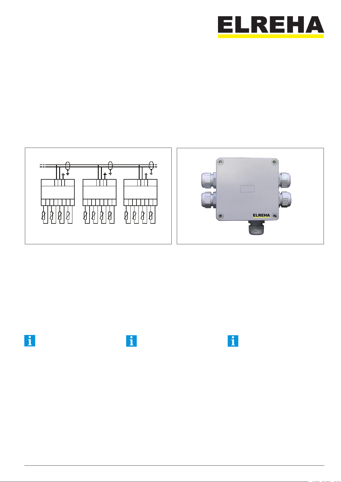
• Les câbles de sonde doivent être blindés et séparés des
câbles de puissance. Le blindage doit être relié d‘un côté
à la terre, au plus près du régulateur afin d‘éviter les
problèmes d‘induction !
• La section des câbles d‘extension de sonde doit être
d‘au moins 0,5mm².
• Eviter de placer l’appareil à proximité de contacteurs
de forte puissance. Les interférences électro-magnétiques
peuvent conduire à un dysfonctionnement du produit.
• Le câblage de l’interface réseau doit respecter les
exigences spécifiées par le fabricant.
• Toutes les sondes connectées doivent être du même type.
L’appareil ne fonctionnera pas si plusieurs types
de sonde sont utilisés en même temps.
• Les sondes de température de type TF ne sont pas
conçues pour être immergées en permanence. Si vous
souhaitez les plonger dans un liquide, il sera nécessaire de
les placer dans un doigt de gant étanche pour les protéger
de la corrosion. Les environnements avec des variations
de température extrêmes peuvent endommager les
sondes.
Other ELREHA Control Unit manuals