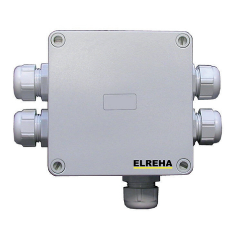
Betriebsanleitung / Manual I/O-Modules Series BMx
Start-up
Mount unit to DIN-rail
Connect databus, note polarity!
Switch power on
Inbetriebnahme
Gerät mechanisch montieren
Datenbusverbindung auflegen, dabei auf Polung achten!
Betriebsspannung einschalten
Seite 2
ALLGEMEINE ANSCHLUSS- UND SICHERHEITSHINWEISE
Diese Anleitung muss dem Nutzer jederzeit zugänglich sein.
Bei Schäden, die durch unsachgemäße Handhabung oder
Nichtbeachten der Anleitung und der Sicherheitshinweise
verursachtwerden,übernehmenwirkeineHaftung!Insolchen
Fällen erlischt jeglicher Garantieanspruch.
Falls Sie Beschädigungen feststellen, so darf das Produkt
NICHT an Netzspannung angeschlossen werden!
Es besteht Lebensgefahr!
Ein sicherer Betrieb ist eventuell nicht mehr möglich wenn:
• das Gerät sichtbare Beschädigungen aufweist,
• das Gerät nicht mehr funktioniert,
• nach längerer Lagerung unter ungünstigen Bedingungen,
• starken Verschmutzungen oder Feuchtigkeit,
• nach schweren Transportbeanspruchungen.
• Die Installation und Inbetriebnahme des Gerätes darf
nur durch eine Elektrofachkraft oder unter der Auf-
sicht einer Elektrofachkraft durchgeführt werden.
• Halten Sie das Gerät bei der Montage sicher vom
Stromnetz getrennt! Stromschlaggefahr!
• Betreiben Sie das Gerät niemals ohne Gehäuse.
Stromschlaggefahr!
• Eine vorhandene PE-Klemme des Gerätes muss auf
PE gelegt werden! Stromschlaggefahr! Zusätzlich funk-
tioniert die interne Filterung von Störungen nur einge-
schränkt, fehlerhafte Anzeigen können die Folge sein.
• Das Gerät darf nur für den auf Seite 1 beschriebenen
Einsatzzweck verwendet werden.
• Bitte beachten Sie die am Einsatzort vorgeschriebenen
Sicherheitsvorschriften und Normen.
• Bitte prüfen sie vor dem Einsatz des Reglers dessen
technische Grenzen (siehe Technische Daten), z.B.:
- Spannungsversorgung (auf dem Gerät aufgedruckt)
- Vorgeschriebene Umgebungsbedingungen
(Temperatur- bzw. Feuchtegrenzen)
- Maximale Belastung der Relaiskontakte im Zusammen-
hang mit den maximalen Anlaufströmen der
Verbraucher (z.B. Motore, Heizungen).
Bei Nichtbeachtung sind Fehlfunktionen oder
Beschädigungen möglich.
• Vermeiden Sie den Einbau in unmittelbarer Nähe von
großen Schützen (starke Störeinstrahlung möglich).
• Bitte beachten Sie bei der Installation von Datenleitungen
die dafür nötigen Anforderungen.
Hinweis
Gefahr
Achtung
CONNECTION INFORMATION & SAFETY INSTRUCTIONS
The guarantee will lapse in case of damage caused by failure
to comply with these operating instructions! We shall not be
liable for any consequent loss! We do not accept liability for
personal injury or damage to property caused by inadequate
handling or non-observance of the safety instructions! The
guarantee will lapse in such cases.
If you notice any damage, the product may not be connected
to mains voltage! Danger of Life!
A riskless operation is impossible if:
• The device has visible damages or doesn't work
• After a long-time storage under unfavourable conditions
• The device is strongly draggled or wet
• After inadequate shipping conditions
• Never use this product in equipment or systems that are
intended to be used under such circumstances that may
affect human life. For applications requiring extremely
high reliability, please contact the manufacturer first.
• The product may only be used for the applications
described on page 1.
• Electrical installation and putting into service must be
done from qualified personnel.
• During installation and wiring never work when the
electricity is not cut-off ! Danger of electric shock!
• Never operate unit without housing.
Danger of electric shock!
• All ‘PE’ terminals must be connected to ground.
Danger of electric shock! Additionally, the internal noise
filter will not work, faulty indicated values may occur.
• Please note the safety instructions and standards of your
place of installation!
• Before installation: Check the limits of the controller and
the application (see tech. data). Check amongst others:
- Make sure that all wiring has been made in accordance
with the wiring diagram in this manual.
- Supply voltage (is printed on the type label).
- Environmental limits for temperature/humidity.
- Maximum admitted current rate for the relays. Compare
it with the peak start-up currents of the controlled loads
(motors, heaters,etc.).
Outside these limits malfunction or damages may occur.
• Mounting the controller close to power relays is unfavourable.
Strong electro-magnetic interference, malfunction may occur!
• Take care that the wiring of interface lines meets the
necessary requirements.
Danger
CAUTION
Notice
Dok. erstellt: 6.7.16, tkd/jr geprüft: 7.7.2016, ek/jk freigegeben: 7.7.2016, mv/mh übersetzt: Korr:
We state the following: When operated in accordance with the technical manual, the criteria have been met that are outlined in the EMC-Directive
2014/30/EC and the Low Voltage Directive 2014/35/EC.
This declaration is valid for those products covered by the technical manual which itself is part of the declaration. Following standards were consulted
for the conformity testing to meet the requirements of EMC and Low Voltage Guidelines:
EN 55011:2009+A1:2010, EN 61010-1:2010, EN 61326-1:2013
This statement is made from the manufacturer / importer by:
ELREHA Elektronische Regelungen GmbH Werner Roemer, Technischer Leiter, Technical Director
D-68766 Hockenheim
www.elreha.de Hockenheim.............5.7.2016.......................................................
(Name / Anschrift / name / adress) Ort/city Datum/date Unterschrift/sign
EC Declaration of Conformity


