Dräger REGARD 7000 User manual

Instructions for use
REGARD 7000

,QVWUXFWLRQVIRUXVH _ 5(*$5'
This page has been left blank intentionally.

,QVWUXFWLRQVIRUXVH_ 5(*$5'
Contents
Contents
Safety-related information 8
Conventions in this document 9
Meaning of the warning notes 9
Typographical conventions 9
Brands 9
System overview 10
System description 10
Safety design 10
REGARD 7000 components 11
Intended Use 12
Limitations on use 12
Approvals 12
Marking 13
Approvals granted 13
Approved components for functional safety and measuring
function for flammable gases, oxygen and toxic gases 14
Approved components according to NFPA 72 15
Approved components for plants in the maritime sector 15
Accessories relevant for approval 16
Copyright and licensing agreements 16
System components 17
Docking Station 17
Docking Station 4-/8-Slot 17
Technical data Docking Station 4/8 slots 18
Modules 19
4-20 mA Input Module / HART® 19
Modbus RTU Master Module 22
Digital Input Module 24
Relay Module 240 V AC / 240 V AC complex 29
Relay Module 24 V DC / 24 V DC complex 31
Gateway Module 32
Long Distance Gateway 36
Bridge Module 38
Slot cover 39
Terminal block 40
Terminal Block 24 pole DC 40
Terminal Block 24 pole AC 41
Terminal Block 16 pole 42
Terminal Block 16 pole Res 43
Terminal Block 2 pole / 3 pole 44
Dashboard 45
Add-on functionalities 45
Advanced Dashboard 6RU 46
Advanced Dashboard PM 46
Standard Dashboard 3RU 47

,QVWUXFWLRQVIRUXVH_ 5(*$5'
Contents
Installation & commissioning 48
System design 48
System structure 48
System limits 49
Prerequisites for the system structure 50
Additional requirements for plants with measuring function
for flammable gases, oxygen or toxic gases 51
System structure variants 51
Assembly and installation 52
Commissioning 53
Requirements for commissioning 53
Preparation for operation 53
Switching on REGARD 7000 54
Configuring the REGARD 7000 54
Control 55
Log user in or out 55
Screen structure (list view) 56
User roles 56
List and column view 57
Navigation bar 57
Navigation buttons 58
Title bar of the channel display (list view) 59
Buttons on the menu bar 59
Buttons of the display selection bar 60
Displays of progress bar 60
Generally used icons 61
Channel view of the module types 62
Icons in the measured value and status field of the channel display
with 4 to 20 mA input channels 62
Icons in the measured value and status field of the channel display
with relay output channels 63
Icons in the measured value and status field of the channel display
with Modbus output channels 64
Icons in the measured value and status field of the channel display
with bridge channels 64
Display prioritisation 64
Status signalling with the presentation of channel states 65
Side bar 66
Alarm confirmation modes 66
Operation 69
Prerequisites for operation 69
Prerequisites for plants in the area of functional safety and
measurement function for flammable gases, oxygen and toxic
gases 69
Prerequisites for plants conforming to NFPA 72 70
Requirements for plants in the maritime sector 71
Special features of operation of the REGARD 7000 in combination
with a REGARD 71
System behaviour 73

,QVWUXFWLRQVIRUXVH_ 5(*$5'
Contents
User role concept 75
View only role 75
Operation role 75
Maintenance role 75
Configuration role 75
Administration role 76
View role 76
During operation 76
Operation role 76
During operation 77
Maintenance role 77
Docking Station maintenance 78
Maintenance of modules 80
Maintenance of channels and ports 81
Dashboard settings 82
Configuration role 83
General configuration procedure 83
Export configuration and reports 85
Save or import configurations 85
Compare system configuration (optional) 86
Copying Port configuration 87
Port configuration 4-20 mA Input Module / HART® 88
Module and port configuration Modbus RTU Master
Module 95
Port configuration Digital Input Module 100
Relay module port configuration 104
Port configuration Gateway Module 110
Port configuration Bridge Module 113
Allocating card numbers of a REGARD system to the
Bridge Module 116
Dashboard settings 116
Administration role 117
Manage users 117
Set automatic login 118
Update dashboard firmware 118
Display and install add-on licences 119
Manage system documentation library (optional) 120
Switching off the dashboard 120
Fault elimination and messages 121
General 121
HART® 131
Maintenance 133
Replacing module (same slot and same configuration) 133
Add module 133
Replace module (new slot) 134
Replace transmitter 134
Additional system changes 134

,QVWUXFWLRQVIRUXVH_ 5(*$5'
Contents
REGARD 7000 configuration software 135
Introduction 135
Contents of these help pages 135
Setting up an account 135
Operating concept for the software 135
Program interface 135
Editing configuration settings 136
Software operating modes 137
Offline configuration mode 137
Online configuration mode 137
Creating a new system configuration 137
Usable key combinations 137
Create new system 137
Add or remove Docking Station 137
Add or remove module 138
Receive and send configuration data 139
Receive configuration data 139
Send configuration data 139
Compare system configuration (optional) 139
Compare online configuration 139
Compare offline configuration 140
Save and open configuration files 140
Save configuration files 140
Save a copy of a configuration file 140
Open configuration files 140
Set and change configurations 140
Set parameters 140
Copying Port configuration 141
Select transmitter 141
Select measured gas 141
Set measuring range 141
Create component and parameter reports 142
Create and save component report 142
Create and save parameter report 142
Display Dashboard view 142
Select the PC interface 142
Change language of the configuration software 143
Disposal 144
Technical data 145
Glossary 147
Annex 149
Compatible REGARD components 149
Abbreviations 149
Modbus command structure 150
Example: Read register 150
Example: Write register 150

,QVWUXFWLRQVIRUXVH_ 5(*$5'
Contents
Meaning of fields 151
Assignment of the input register 151
Channel types 153
Structure of the state register of REGARD 7000 channels 153
Structure of alarm state information 154
Structure of output state information 154
Assignment of the holding register 155
Diagnostics Information for Modbus RTU Master 156
Structure of notification and confirmation register
(acknowledge/notify register) 157
Meaning of data types 158
PROFIBUS DP and PROFINET command setup 159
Downloading the GSD(ML) file 159
Configuration via the GSD(ML) file modules 159
Declaration of conformity 162

,QVWUXFWLRQVIRUXVH_ 5(*$5'
Safety-related information
1 Safety-related information
– Before using this product, carefully read these instructions for use and those of
the associated and connected products (e.g. transmitter, alarm device).
– Strictly follow the instructions for use. The user must fully understand and strictly
observe the instructions. The product is only permitted to be used for the
intended use; otherwise the protection provided by the device may be impaired.
– Do not dispose of the instructions for use. Ensure that they are retained and
appropriately used by the product user.
– Only trained and competent users are permitted to use this product.
– Comply with all local and national rules and regulations associated with this
product (e.g. EN/IEC 60079-14).
– Only trained and competent personnel are permitted to inspect, repair and
service the product. Dräger recommend a Dräger service contract for all
maintenance activities and that all repairs are carried out by Dräger.
– Use only genuine Dräger spare parts and accessories, otherwise, the proper
functioning of the product may be impaired.
– Do not use a faulty or incomplete product. Do not modify the product.
– Notify Dräger in the event of any component fault or failure.
– Do not operate in explosion-hazard areas. This device is neither approved nor
certified for use in areas where combustible or explosive gas mixtures are likely
to occur.
– Follow the directions of EN/IEC 60079-29-2 for measurement of flammable
gases or oxygen.
– Follow the directions of EN 45544-4 for measurement of toxic gases or oxygen.

,QVWUXFWLRQVIRUXVH_ 5(*$5'
Conventions in this document
2 Conventions in this document
2.1 Meaning of the warning notes
The following alert messages are used in this document to provide and highlight
areas of the associated text that require a greater awareness by the user. A
definition of the meaning of each alert message is as follows:
2.2 Typographical conventions
2.3 Brands
Alert icon Signal word Consequences in case of non-obser-
vance
WARNING Indicates a potentially hazardous situation.
If not avoided, it could result in death or
serious injury.
CAUTION Indicates a potentially hazardous situation.
If not avoided, it could result in physical
injury. It may also be used to alert against
unsafe practices.
NOTICE Indicates a potentially hazardous situation.
If not avoided, it could result in damage to
the product or environment.
Text Text in bold identifies labels on the device and text on the display.
►This triangle in warnings identifies the options available for avoiding
the hazard.
> The greater-than symbol identifies a navigation path in a menu.
This symbol indicates information that may make the use of this
product easier.
Brand Brand owner
REGARD®Dräger
ServiceConnect®Dräger
HART®HART Communication Foundation
Unitronic®Lapp GmbH
PROFIBUS®, PROFINET®PROFIBUS & PROFINET International (PI)

,QVWUXFWLRQVIRUXVH_ 5(*$5'
System overview
3 System overview
3.1 System description
REGARD 7000 is a modular control unit for gas and fire alarm systems. The control
units consist of one or more Docking Stations, each of which can contain up to
8 modules. The REGARD 7000 is a system with distributed intelligence. Each
module has the intelligence required for its function. A REGARD 7000 system can
also be wired to create a system of up to 6 remote units (docking stations and
modules). The complete system can have a maximum of 24 Docking Stations and
can control 1536 channels. Input and output channels may be distributed as
required (1 to 1535 up to 1535 to 1).
The modules are either input or output modules. Every module generally has 8
channels. All modules have their own intelligence and operate autonomously. The
system is designed so failure of a module only affects the modules dependent on
the failed module, i.e. the faulty module only generates a secondary fault in the
modules that expect data from the faulty module. Other modules are not affected. In
addition, every fault in the system is signalled on each Docking Station via the fault
relay (System Fault Relay, SFR). All modules can be replaced during operation
without shut-down of the supply voltage.
3.2 Safety design
REGARD 7000 is designed in accordance with the requirements for SIL2 and for
SIL3 with the applicable system layout.
REGARD 7000 is designed as a system with distributed intelligence that does not
require a master controller (masterless). The modules communicate with one
another deterministically (predetermined) using a proprietary safety Ethernet
network protocol. All bus devices send their current data in a data packet to all other
bus devices once every second. Bus devices that derive actions from this
information (e.g. relay modules) expect a valid data package from every module
30748
Input Output
Control room
Configuration
Diagnostic

,QVWUXFWLRQVIRUXVH_ 5(*$5'
System overview
once every second. The modules accept no more than 2 faulty data packets in
succession. If more than 2 faulty data packets in succession are received, a fault is
triggered and the fault relay (SFR) in the Docking Station is activated.
Due to the communication without a master device (masterless), there is no
component in the system whose failure would trigger a failure of the complete
system (Single Point of Failure). The modules are time-synchronised throughout
the system by a module that is automatically selected when the system is started.
In the event of a fault in this module, the time function is automatically transferred to
another module in the system and a fault is signalled via the SFR. All modules not
influenced by the faulty module continue to operate.
Special states in the system, such as Inhibit, are also displayed by the special state
relay (SSR) at the Docking Station.
The alarm is triggered a maximum of 3.3 seconds after measurement of an alarm
condition.
The system continuously monitors the correct function. Every system fault results in
drop-out (normally energized) of the respective fault relay on the Docking Station.
Systems with requirements as per SIL3 can be implemented with REGARD 7000
by using a structure with redundant channels.
Dräger recommends selection of fault-tolerant configurations for safety-relevant
applications, such as acknowledgement of alarms using 2 independent switches.
3.3 REGARD 7000 components
System components
REGARD 7000
Order number Software /
Firmware version
Docking Station 8-Slot 83 22 286 N/A
Docking Station 4-Slot 83 22 320 N/A
Advanced Dashboard 6RU 83 26 850 1.00.xx - 1.03.xx
Advanced Dashboard PM 83 26 860 1.00.xx - 1.03.xx
Standard Dashboard 3RU 83 27 840 1.03.xx
Adv Dashboard 6RU Basic Unit 83 28 255 1.00.xx - 1.03.xx
Adv Dashboard PM Basic Unit 83 28 260 1.00.xx - 1.03.xx
Std Dashboard 3RU Basic Unit 83 28 250 1.03.xx
4-20 mA Input Module 83 24 001 1.00.xx - 1.01.xx
4-20 mA Input Module / HART 83 27 250 1.01.xx
Digital Input Module 83 24 003 1.00.xx
Relay Module 24 V DC 83 23 250 1.00.xx
Relay Module 240 V AC 83 24 010 1.00.xx
Relay Module 24 V DC complex 83 24 874 1.00.xx
Relay Module 240 V AC complex 83 24 875 1.00.xx
Bridge Module 83 24 870 1.00.xx
Modbus RTU Gateway Set 83 24 872 1.00.xx
Modbus RTU Master 83 28 199 1.00.xx
Long Distance Gateway Set I 83 23 815 N/A
Slotcover 83 23 812 N/A

,QVWUXFWLRQVIRUXVH_ 5(*$5'
System overview
Dräger recommends performing a dashboard firmware update when expanding
REGARD 7000 with modules with a firmware version > 1.00.xx. The latest version
of the dashboard firmware can be downloaded free of charge via the
ServiceConnect® web portal (www.serviceconnect.draeger.com). Using dashboard
firmware that is not up-to-date means that not all features of the new modules may
be fully supported.
3.4 Intended Use
REGARD 7000 is a modular control unit for gas and fire warning systems.
The REGARD 7000 system continuously monitors production facilities for the
following conditions:
– The presence of gas and/or vapour concentrations in the ambient air.
– The outbreak of fire.
The REGARD 7000 system has the following functions:
– The power supply of the connected transmitters and sensors.
– The evaluation of all measurement and status signals.
– The actuation of the associated alarm devices.
All measured values and important system parameters can be displayed
continuously on one or more dashboards and sent to primary control centres via a
gateway module.
3.5 Limitations on use
REGARD 7000 is not designed for use in process control.
The REGARD 7000 network is only permitted to be used for REGARD 7000
communication. Connection to a general IT network is not permitted, for example.
3.6 Approvals
REGARD 7000 is approved under IEC/EN 61508:2010 and EN 50402:2017 for
SIL 2 applications or for SIL 3 with the corresponding plant setup. For details of the
configuration and system layout for SIL 2 or SIL 3 see the Dräger REGARD 7000
Safety Manual (order no. 90 33 497).
REGARD 7000 is approved for the measurement of
Terminal Block 24 pole AC 83 24 016 N/A
Terminal Block 24 pole DC 83 24 020 N/A
Terminal Block 2 pole 83 24 871 N/A
Terminal Block 16 pole 83 24 017 N/A
Terminal Block 16 pole res 83 28 202 N/A
REGARD 7000 Configuration Soft-
ware
N/A ≥01.02.xx
REGARD 7000 PC-Software Key 83 27 253 N/A
System components
REGARD 7000
Order number Software /
Firmware version

,QVWUXFWLRQVIRUXVH_ 5(*$5'
System overview
– flammable gases and vapours under ATEX
– oxygen inertisation measurements under ATEX
– oxygen and toxic gases
REGARD 7000 is suitable for use in setting up gas and fire alarm systems in
accordance with NFPA 72:2016. The Digital lnput modules types and all relay
modules can be used for this purpose. The Digital Input module offers the
monitoring function according to NFPA 72 Class B; the connecting lines between
the relay outputs and the switching elements should be monitored by suitable
external devices.
3.6.1 Marking
3.6.2 Approvals granted
Measurement technology for flammable gases and oxygen (inertisation
measurement)
Measurement technology for toxic gases as well as the measurement of
oxygen deficiency and oxygen enrichment
Functional safety
0158
BVS 16 ATEX G 003 X
PFG 16 G 006 X
0098-XXXX
II (1) G
II (1) D
Inspection authority: DEKRA EXAM GmbH
Standards: EN 60079-29-1:2016
EN 50104:2010
EN 50271:2010
Test number: BVS 16 ATEX G 003 X
Inspection authority: DEKRA EXAM GmbH
Standards: EN 45544-1:2015
EN 45544-2:2015
EN 45544-3:2015
EN 50271:2010
EN 50104:2010
Test number: PFG 16 G 006 X
Inspection authority: TÜV Rheinland Industrie Service GmbH
Standards: EN 50402:2017
IEC/EN 61508-1:2010
IEC/EN 61508-2:2010

,QVWUXFWLRQVIRUXVH_ 5(*$5'
System overview
Maritime sector
3.6.3 Approved components for functional safety and measuring
function for flammable gases, oxygen and toxic gases
The following components have been tested and approved for operation in a safety
or measuring function:
The following components have been tested and approved for operation in a
measuring function:
IEC/EN 61508-3:2010
Certificate: 968/FSP 1374.00/17
Inspection authority: DNV GL SE
Standards: IEC 60533:2015
IEC 60945:2002+A1:2008
IEC 60092-504:2016
Certificate: MED B 00002Z6 (MED)
TAA00001S9 (DNV)
Module Software version
4-20 mA Input Module ≥01.00.01
4-20 mA Input Module / HART®≥01.01.02
Digital Input Module ≥01.00.01
Relay Module 240 V AC ≥01.00.01
Relay Module 240 V AC complex ≥01.00.01
Relay Module 24 V DC ≥01.00.01
Relay Module 24 V DC complex ≥01.00.01
Long Distance Gateway N/A
Slotcover N/A
Docking Station 8-Slot N/A
Docking Station 4-Slot N/A
Terminal Block 24 pole AC N/A
Terminal Block 24 pole DC N/A
Terminal Block 2 pole N/A
Terminal Block 16 pole N/A
Terminal Block 16 pole res N/A
Module Software version
Bridge Module ≥01.00.02
Modbus RTU Gateway Set1)
1) Not for safety-related evaluation of measured values and alarms.
≥01.00.01
PROFIBUS DP Gateway Set1) ≥01.00.06
PROFINET Gateway Set1) ≥01.00.06

,QVWUXFWLRQVIRUXVH_ 5(*$5'
System overview
The following display elements and software components have been tested and
approved for operation in a measuring function:
3.6.4 Approved components according to NFPA 72
The following components have been tested and approved for operation according
to NFPA 72:
3.6.5 Approved components for plants in the maritime sector
Module Software version
Advanced Dashboard 6RU ≥01.01.00
Advanced Dashboard PM ≥01.01.00
Standard Dashboard 3RU ≥01.03.00
Adv Dashboard 6RU Basic Unit ≥01.01.00
Adv Dashboard PM Basic Unit ≥01.01.00
Std Dashboard 3RU Basic Unit ≥01.03.00
Module Software version
Digital Input Module ≥01.00.01
Relay Module 240 V AC ≥01.00.01
Relay Module 240 V AC complex ≥01.00.01
Relay Module 24 V DC ≥01.00.01
Relay Module 24 V DC complex ≥01.00.01
Slotcover N/A
Docking Station 8-Slot N/A
Docking Station 4-Slot N/A
System components
REGARD 7000
Order number Software /
Firmware version
Docking Station 8-Slot 83 22 286 N/A
Docking Station 4-Slot 83 22 320 N/A
Advanced Dashboard 6RU 83 26 850 1.00.xx - 1.03.xx
Advanced Dashboard PM 83 26 860 1.00.xx - 1.03.xx
Standard Dashboard 3RU 83 27 840 1.03.xx
Adv Dashboard 6RU Basic Unit 83 28 255 1.00.xx - 1.03.xx
Adv Dashboard PM Basic Unit 83 28 260 1.00.xx - 1.03.xx
Std Dashboard 3RU Basic Unit 83 28 250 1.03.xx
4-20 mA Input Module 83 24 001 1.00.xx - 1.01.xx
4-20 mA Input Module / HART 83 27 250 1.01.xx
Digital Input Module 83 24 003 1.00.xx
Relay Module 24 V DC 83 23 250 1.00.xx
Relay Module 240 V AC 83 24 010 1.00.xx
Relay Module 24 V DC complex 83 24 874 1.00.xx
Relay Module 240 V AC complex 83 24 875 1.00.xx
Bridge Module 83 24 870 1.00.xx
Modbus RTU Gateway Set 83 24 872 1.00.xx
Long Distance Gateway Set I 83 23 815 N/A

,QVWUXFWLRQVIRUXVH_ 5(*$5'
System overview
3.6.6 Accessories relevant for approval
3.7 Copyright and licensing agreements
Parts of the software libraries used in the dashboard software are the copyright of
other parties. They have been published under LGPLv2.1, MIT or BSD licences.
The licence terms, conditions and the source code of the software libraries may be
downloaded from Dräger ServiceConnect®
(https://www.serviceconnect.draeger.com) for a period of at least 3 years after
purchase of the software as a supplement to the instructions for use. The access
data for Dräger ServiceConnect®is supplied with the REGARD 7000 dashboard.
PROFIBUS DP Gateway Set 83 28 191 ≥01.00.06
PROFINET Gateway Set 83 28 196 ≥01.00.06
Slotcover 83 23 812 N/A
Terminal Block 24 pole AC 83 24 016 N/A
Terminal Block 24 pole DC 83 24 020 N/A
Terminal Block 2 pole 83 24 871 N/A
Terminal Block 16 pole 83 24 017 N/A
Terminal Block 16 pole res 83 28 202 N/A
REGARD 7000 Configuration Soft-
ware
N/A ≥01.02.xx
REGARD 7000 PC-Software Key 83 27 253 N/A
Retention staple set, 7 pcs. 83 27 257 N/A
System components
REGARD 7000
Order number Software /
Firmware version
Designation Order no.
Code plate non-specific, 5 units 83 27 046
Docking station stopper, 6 units 83 27 045
Retention staple set, 7 pcs. 83 27 257

,QVWUXFWLRQVIRUXVH_ 5(*$5'
System components
4 System components
4.1 Docking Station
The Docking Station forms the basis assembly of the REGARD 7000 system. Up to
4 or up to 8 REGARD 7000 modules can be plugged into the Docking Station.
The Docking Station manages the power supply of all its modules and via the
modules it indirectly powers the associated transmitters (for transmitters with a
max. power consumption of 500 mA; an external power source is required for
greater power requirements).
The Docking Station is used for all system communication between the modules
and to and from other Docking Stations.
In addition, it forms the beam for accommodating the Terminal Blocks.
4.1.1 Docking Station 4-/8-Slot
Docking Station 4-Slot for up to 4 modules.
Docking Station 8-Slot for up to 8 modules.
29664
1 Contact assignment for power supply to the Docking Station
Contacts of the same name are parallel circuits.
2 Reset button for Ethernet communication (for Service only).
3 Fastening holes (6x)
4 Module slots Slot 1 to Slot 8 / Slot 4
5 Connector for function earth
6 4 Ethernet connections for additional Docking Stations, Dashboard, laptop for
configuration. The bottom Ethernet port is the easiest for connecting and dis-
connecting a laptop.
7 Ethernet LED (yellow), shows the status of the Ethernet speed:
– LED on: 100 Mbit/s
– LED off: 10 Mbit/s
8 Ethernet LED (green), flashes during data transfer.
2
COM
NO
NC
10
85
Slot2 Slot3 Slot4 Slot5 Slot6 Slot7 Slot8Slot1
+ 1 -
+ 2 -
1
COM
NO
NC
9
3
4
7
6

,QVWUXFWLRQVIRUXVH_ 5(*$5'
System components
NOTICE
Device damage!
If the supply voltage of 30 V is exceeded, the Docking Station may be destroyed.
►Do not exceed a supply voltage of 30 V.
Cover unused module slots with a Slotcover.
4.1.2 Technical data Docking Station 4/8 slots
9 Contact assignment for special state relay (SSR)
In the inactive state the SSR is not operational (energized on alarm). If there is
no special state, NC and Common are connected. Activation by a special state.
10 Contact assignment for fault relay (SFR)
In the normal state the SFR is energized and operational (normally energized).
In the fault-free operating state (power supply present), NC and Common are
connected.
Drop-out in case of fault, e.g.:
– Hardware fault on one or more modules of the Docking Station.
– Unassigned slot on a Docking Station.
– Impermissible supply voltage for the Docking Station.
– Maximum current of the Docking Station exceeded.
– Missing transmitter or fault state of a connected transmitter.
– Short circuit on transmitter connection lines.
Connection terminals: Plug contacts for wire cross-sections from 0.08 to
2.5 mm2.
Operational voltage: 24 V (18 to 30 V) DC
Power input: Docking Station 4-Slot:
max. 11 A (depending on the number of installed mod-
ules and connected transmitters)
Docking Station 8-Slot:
max. 22 A (depending on the number of installed
modules and connected transmitters)
Power loss: max. 15 W at 24 V
SFR output: min. 5 V, 10 mA, max. 30 V, 2 A switching capacity;
a fuse is required to protect the SFR output.
SSR output: min. 5 V, 10 mA, max. 30 V, 2 A switching capacity;
a fuse is required to protect the SSR output.
Number of modules for
each Docking Station
Docking Station 4-Slot: max. 4
Docking Station 8-Slot: max. 8

,QVWUXFWLRQVIRUXVH_ 5(*$5'
System components
4.2 Modules
4.2.1 4-20 mA Input Module / HART®
Input module in 2 variants (with or without HART®) for connection of up to eight 4-
20 mA transmitters. A 4-20 mA module shows the current values from 4 mA to
20 mA in linear form on the measuring range (0 to the end of the measuring range).
From firmware version ≥01.01.01 the current values 4-20 mA can also be mapped
to a completely or partially negative measuring range. Regions of measurement
range underrun and overrun and special states and warnings of the transmitter can
be configured. For further information, see the following chapter: "Port configuration
4-20 mA Input Module / HART®", page 88
Monitoring functions – input voltage monitoring 18-30 V
The SFR is activated for voltage underrun; the
power supply is shut down in case of voltage over-
run and the SFR is activated, then a restart is
required.
– Total current monitoring
Docking Station 4-Slot:
shut-down at >10.2 A (max. 12 A), then a restart is
required.
Docking Station 8-Slot:
shut-down at >20.4 A (max. 22 A), then a restart is
required.
– Temperature monitoring
Shut-down of the Docking Station and activation of
the SFR, then a restart is required.
29915
1 Input 1 to 8 and channel display
Lights if a loop current is flowing.
2 Fault display
Lights if there is a module or channel error.
3 LED
Lights when the module is under power.
4 Data transfer display
Flashes when the module is communicating.
REGARD 7000
AI 4 - 20 mA/HART
I/P 1
I/P 2
I/P 3
I/P 4
I/P 5
I/P 6
I/P 7
I/P 8
1
2
3
4
REGARD 7000
AI 4 - 20 mA
I/P 1
I/P 2
I/P 3
I/P 4
I/P 5
I/P 6
I/P 7
I/P 8
1
2
3
4

,QVWUXFWLRQVIRUXVH_ 5(*$5'
System components
Application notes
One module 4-20 mA Input / HART®always provides 8 physical ports. A Port
configured with a channel ID forms an input channel. Even so, unconfigured and
thus unused Ports occupy the corresponding number of Ports in the overall system.
WARNING
Missing gas alarm
With supply power to a connected transmitter via the 4-20 mA Input / HART
module, note that the current consumption of the transmitter depends on the line
length and the cross-section of the transmitter supply lines. In very unfavourable
circumstances this may mean that the supply voltage approaches the shut-down
limit of the channel and the current monitoring limit will be exceeded with a signal
current. In this case a measured signal may result in the shut-down of the channel
and as a result a module error that will also be signalled on the Docking Station via
the SFR. This will suppress a gas alarm configured in this current range. The same
behaviour is also found with the connection of multiple transmitters for the total
current monitoring of a module for all channels. In the most unfavourable case this
may result in shut-down of the complete module and failure of the associated
channels.
►When designing the supply currents for the transmitters, the supply voltage per
channel must be at least 20 mA below the permissible channel short-circuit
detection current (500 mA or 250 mA) and at least 160 mA below the module
short-circuit detection current (2 A). In case of doubt, during commissioning the
supply current to the single channel and the total supply currents on all channels
of the module must be tested to ensure compliance with the above conditions.
Use of signal duplicators
For the use of REGARD 7000 and one additional signal receiver, 4-20mA signal
duplicators can be used.
Dräger has qualified the following components for this purpose:
Manufacturer Order no. Order no.
Phoenix Contact MACX MCR-EX-SL-RPSSI-2I 28 65 36 6
Phoenix Contact MACX MCR-EX-SL-RPSSI-2I-SP 29 24 23 6
41464
PLC
24 V
Signal
4-20 mA
4-20 mA Input
4-20 mA
PWR- PWR-
PWR+
PWR-
PWR+PWR+
OR
OR
Polytron
7000
Polytron
8xx0
+4.1 IN active
-4.2
+5.1 IN passive
OUT 1
OUT 2
-5.2
+3.1
-3.2
+2.1
-2.2
1.1+24V
1.2 GND
1.1 2.1 3.1 4.1 5.1 6.1 7.1 8.1
1.2 2.2 3.2 4.2 5.2 6.2 7.2 8.2
1.3 2.3 3.3 4.3 5.3 6.3 7.3 8.3
Table of contents
Other Dräger Control Unit manuals

Dräger
Dräger RailGard-S1 User manual

Dräger
Dräger PAS ASV User manual

Dräger
Dräger REGARD 2400 User manual

Dräger
Dräger Regis 300 User manual

Dräger
Dräger BS8468-1 User manual

Dräger
Dräger Area User manual

Dräger
Dräger PAS ASV User manual

Dräger
Dräger Scio Four User manual

Dräger
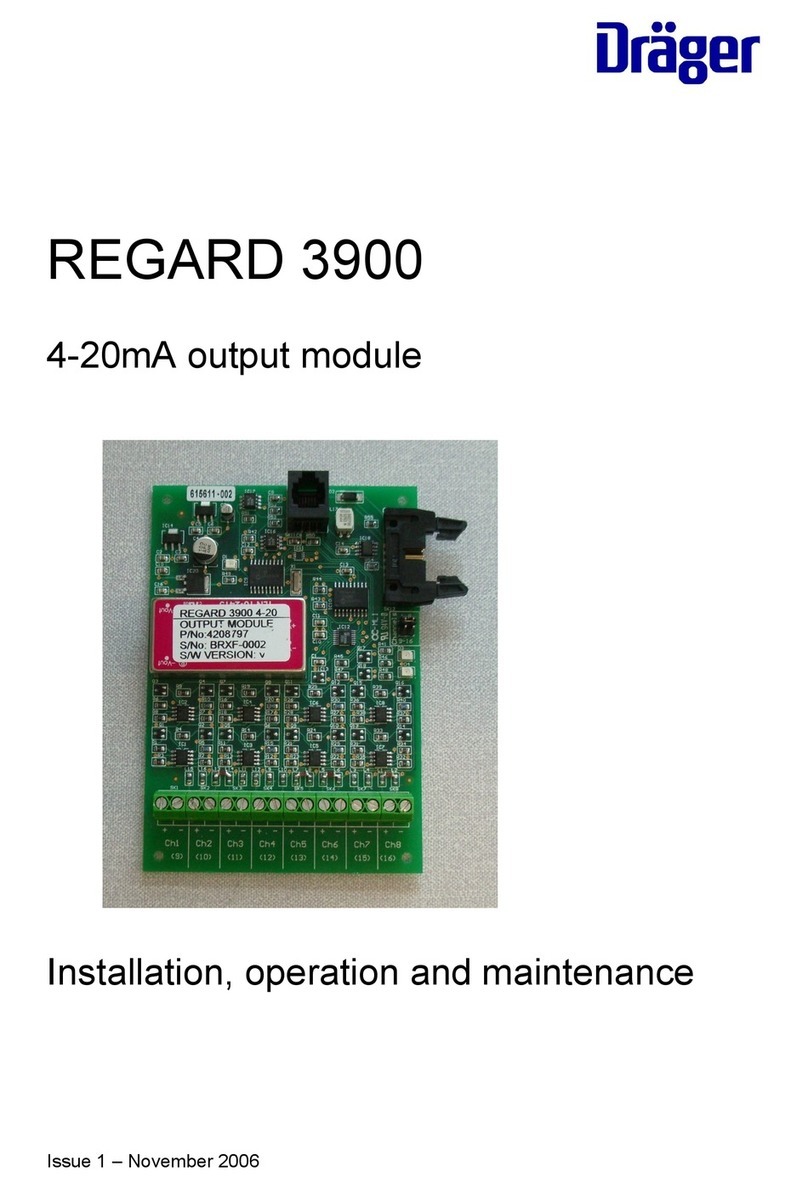
Dräger REGARD 4208797 Installation and operating instructions

Dräger
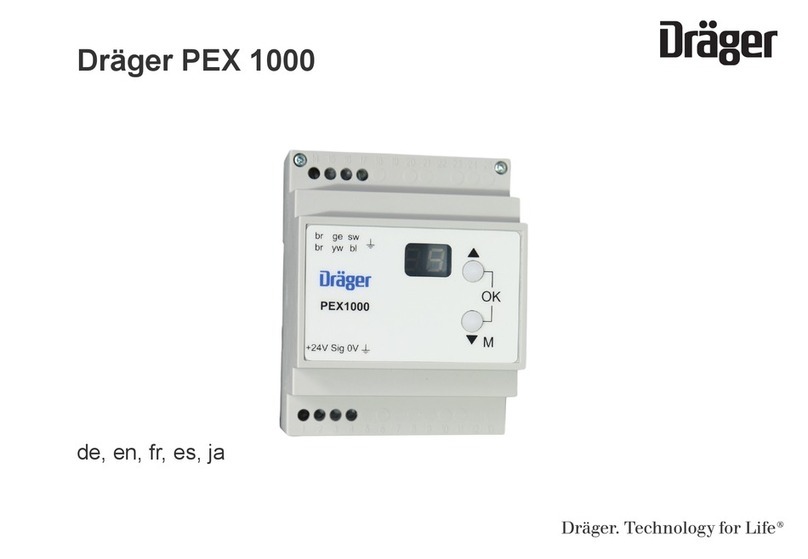
Dräger PEX 1000 User manual