ELREHA MiniMEP Series User manual

Technical Manual
Temperature- & Humidity Recording System
02.07.96 12:30
Room 1 -23.5°C
Brief Description
MiniMEP Recording Systems (dataloggers) are designed for
paperless longtime data recording of temperature values and
(dep. on type) relative humidity. Thus the user is able to get a
proof about the course of temperatures and humidity in
corresponding rooms, without application of additional
components as e.g. mechanical printers or PC's.
It is ideal for compliance with 21 CFR process control for food
storage regulations and HACCP Quality Assurance Systems.
The wide temperature range qualifies a MiniMep for both freezing
applications and 'hot' industrial processes.
The Recording System MiniMEP meets all requirements of
the EU Standard EN 12830.
Functions
zRecords the values of temperature sensors resp. humidity
transmitters for up to 20 years !
Adjustable storage interval.
Example 1: 781 days with a 5 minute interval.
Example 2: > 6 years with a 15 min. interval
zData storage is unlimited even without mains voltage
zReal time clock with typ. 10 years battery backup
zContinuous recording by external lead accu possible *
zAlarm too high/low with time delay for each input
zMonitored sensor inputs
zError message memory shows the last 6 occured errors
zClear assignment of measuring position, time and value
plain text designation in the display
zNetworkable via interface
zLCD dot matrix display, backlighted, 4 languages
zDisplay shows actual temperature, time and date
zLets you view all recorded values any time
zEasy operating by 3 keys
zDigital inputs e.g. for door-contact or other messages *
zIsolated alarm relay and built-in buzzer *
zFour display languages selectable:
german, english, french, dutch
* (not type 404 S, 2404S)
MiniMEP
Nr. 5310965-00/20 E
Please note Operating and
Safety Instructions on page 12 !
Valid for the following types containing Software Version 2.5x:
MiniMEP 404 S, 2404 S
MiniMEP 424 A, 2424 A, 424A/12V
MiniMEP 434 A, 2434 A
MiniMEP 524 A, 2524 A
MiniMEP 534 A, 2534 A

Technical Manual MiniMEP Data Loggerspage 2
Contents
page
General Description ............................................. 2
Operating ............................................................. 3
Programming Access Authorization,
Reset Error Messages, Buzzer/Relay Test,
Error Messages / -codes
Functional Description ......................................... 4
Programming designations .............................. 4
Parameter listing (2)434A, (2)534A .................... 5
Parameter listing (2)404S, (2)424A, (2)524A ..... 6
Connection, Versions 4xx.................................... 7
Connection, Versions 5xx.................................... 9
Dimensons ........................................................... 10
Processing of Data, PC connection,
Unlock of recording system ................................. 11
Installation ........................................................... 12
Cable lenghts ................................................... 12
Connection and Safety Notes ....................... 12
Accu operation ............................................... 12
Start-up ................................................................ 12
Technical Data / Accessories .............................. 13
CE-Statement of Conformity ............................... 14
Appendix: Drilling template, calibration and start-up report
General Description
The MiniMEP data logger series is developed for paperless
recording of temperature resp. humidity values and to store them
for a long period of time.
The unit measures temperatures by high accurate platinium
sensors and stores the values in a non-volatile memory for
unlimited time.
Without additional utilities, the user is able to recall every
recorded value with its date, time and position designation.
If this memory is full, the oldest recorded values will be erased to
get space for the newest values.
The units are available in 2 different housings and memory sizes
(see overview below).
A special version (MiniMEP 434 A/534 A) can record 2 temperature
values and the values of two 4...20 mA-humidity transmitters.
Type- Housing Inputs Recording Digital
Alarm Limits
LC- Input for Memory Cap- Supply
Overview Range inputs Alarm relays Display additional- acity with 15
Accu min. interval
MiniMEP 404 S wall mounting 4x temp. -110/+600°C -- -- X -- 366 days 230V
MiniMEP 2404 S wall mounting 4x temp. -110/+600°C -- -- X -- 366 days 115V
MiniMEP 424 A wall mounting 4x temp. -110/+600°C 3x 230V 1x SPDT X X appr. 6 years 230V
MiniMEP 2424 A wall mounting 4x temp. -110/+600°C 3x 115V 1x SPDT X X appr. 6 years 115V
MiniMEP 424/12V wall mounting 4x temp. -110/+600°C 3x 12VDC 1x SPDT X X appr. 6 years 12V
MiniMEP 434 A wall mounting 2x temp. -110/+600°C 3x 230V 1x SPDT X X appr. 6 years 230V
2x
humidity
0/100% r.F.
MiniMEP 2434 A wall mounting 2x temp. -110/+600°C 3x 115V 1x SPDT X X appr. 6 years 115V
2x
humidity
0/100% r.F.
MiniMEP 524 A panel mounting 4x temp. -110/+600°C 3x 230V 1x SPDT X X appr. 6 years 230V
MiniMEP 2524 A panel mounting 4x temp. -110/+600°C 3x 115V 1x SPDT X X appr. 6 years 115V
MiniMEP 534 A panel mounting 2x temp. -110/+600°C 3x 230V 1x SPDT X X appr. 6 years 230V
2x
humidity
0/100% r.F.
MiniMEP 2534 A panel mounting 2x temp. -110/+600°C 3x 115V 1x SPDT X X appr. 6 years 115V
2x
humidity
0/100% r.F.
Note
The temperature recording system MiniMEP corresponds to
the requirements of the european standard EN 12830.
Please note that according to the standard EN 13486, the
end-user is bound to a continuous check of the units for
operation and accuracy.

Technical Manual MiniMEP Data Loggers page 3
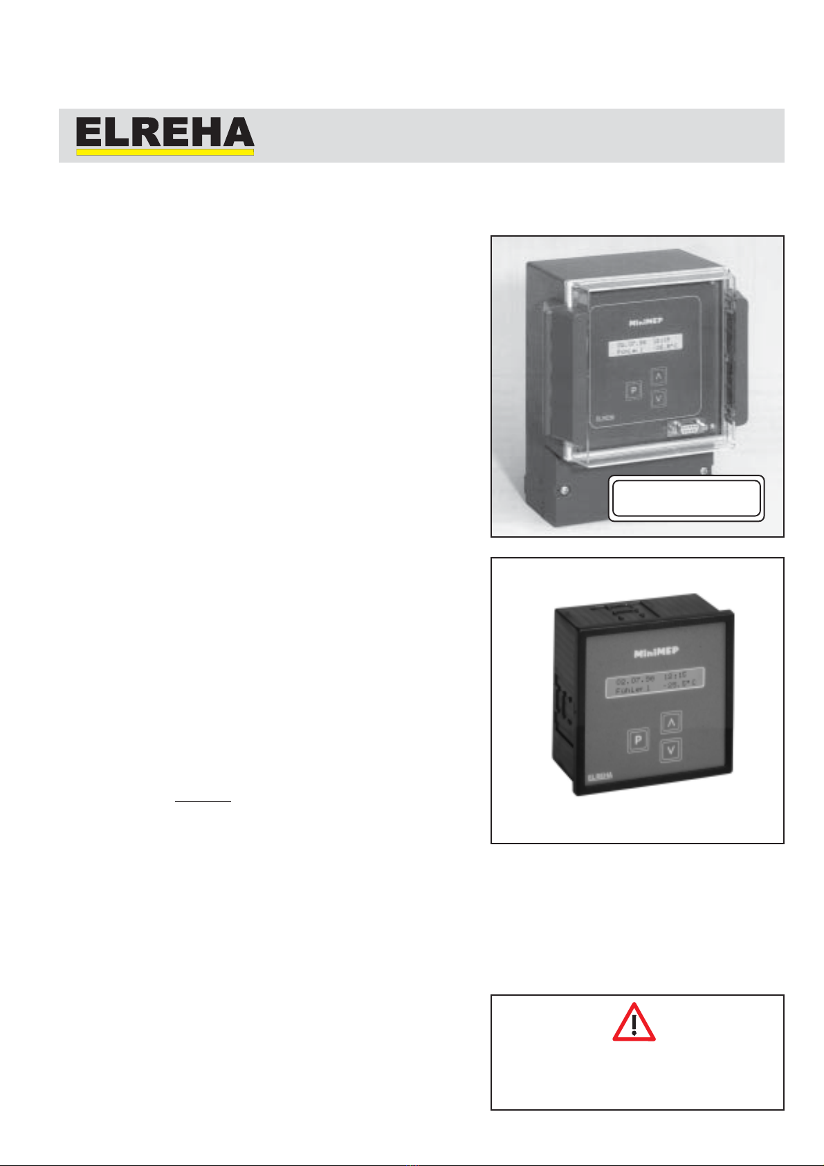
02.07.96 12:27
Sensor 1 -23.5°C
After power-up, the
display shows date,
Current time and value
of sensor 1.
Operating
By pushing the 'up/down' keys you
can select the desired values.
Every keypress brings you to the
next recorded value. Holding an
'up' or 'down' key effects an
automatic, accelerating scrolling.
02.07.96 12:00
sensor 1 -23.5°C
02.07.96 11:45
sensor 1 -23.5°C
02.07.96 12:15
sensor 1 -23.5°C
02.07.96 12:15
sensor 1 -23.5°C 02.07.96 12:15
sensor 2 -12.0°C 02.07.96 12:15
sensor 4 -5.5°C
02.07.96 12:15
sensor 3 21.5°C
serial no
000000
Holding the button 'P' for more than 1 sec. brings you to the parameter page. Select parameter
by the 'up/down' keys (see parameter descriptions on the next pages). Holding the 'P' button
again brings you back to the sensor 1 page.
Every push on button 'P' brings you to the
page of the next sensor.
zSelect desired parameter by the 'up/down' keys
zPress 'P'-key short
zAn access code is
requested
zEnter access code by
'up/down' keys
The code is related from the time of the day as the sum of the hour (0 to 23) plus ‘10’.
Example: At 9:35 a.m. the code is 9 + 10 = 19.
At 9:35 p.m. the code would be 21 + 10 = 31
zNotation of parameter flashes
zChange value by the 'up/down' keys
zPress 'P'-key short
zSelect new parameter if necessary
If you have pressed the 'P' key longer than 1 second or no key is pressed for about 1 minute
after entering the code, the display will switch back to the actual value of sensor 1.
Programming / Access Authorization
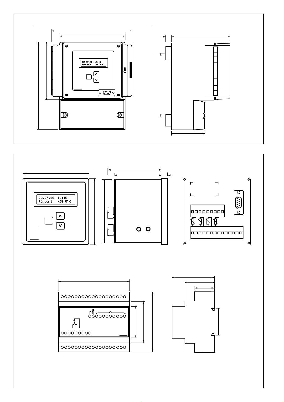
Organisation of the display pages
All parameters and values are partitioned on four
sensor pages and a parameter page. The sensor
pages contain the recorded values. The parameter
page contains setpoints, times, error messages,
etc. Operating the MiniMEP is very easy by three
keys. Key 'P' changes the pages, with the up/down
buttons you are able to scroll the lists or to change
values.
Pages
Overview
Read off recorded values
P P PP
Basic settings / Reading Error messages
02.07.96 12:15
sensor 1 -23.5°C 02.07.96 12:15
sensor 1 -23.5°C
P P
01.07.96 14:15
sensor 4 -17.5°C
01.07.96 14:30
01.07.96 14:45
01.07.96 14:15
sensor 1 -1.0°C
01.07.96 15:00
P
01.07.96 14:15
sensor 3 -24.5°C
01.07.96 14:45
01.07.96 15:00
01.07.96 14:30
01.07.96 14:15
sensor 2 -21.0°C
01.07.96 14:30
01.07.96 14:45
01.07.96 15:00
P P
MINIMEP
serial no
000000
01.07.96 14:30
01.07.96 15:00
01.07.96 14:45
correction
probe selection
push for longer
than 1 second
P P
Identification 1
entry : > 0 <
Reset of Error Messages
If an error message occurs,
push shortly
Buzzer and relay will be reset, but will come
back after the set alarm repetition time. If an
error with a higher priority occurs, it will come
at once.
Buzzer / Relay Test
To test, if the internal buzzer and the alarm
relay works correctly,
push and
at the same time while the actual values are
displayed. The buzzer sounds and the relay
switches off as long as you press the keys.
P
Error codes
If a failure occurs, the MiniMEP generates an
error message by de-activating the alarm relay
and switching ON the internal buzzer.
Additionally, the display starts flashing to get
your attention. Each error message has a
priority level. If several messages occur, the
messages with higher priority are displayed on
top, messages with lower priority are blinded
by the higher ones.
x34-types only: If the current inputs
get > 20mA or if they are not connected:
display shows 100%, no error
message.
'——' ................... no error
'Poff' .................... main power was switched off
prio.1 ........... 'al1' ...................... digital input 1 (Default=al1) was/is not connected
prio.2 ........... 'al2' ...................... digital input 2 (Default=al2) was/is not connected
prio.3 ........... 'door' ................... digital input 3 (Default=door) was/is not connected
prio.4 ........... probe 1, 'p-break' (sensor is broken) or 'p-short' (sensor has short circuit)
prio.5 ........... probe 2, 'p-break' (sensor is broken) or 'p-short' (sensor has short circuit)
prio.6 ........... probe 3, 'p-break' (sensor is broken) or 'p-short' (sensor has short circuit)
prio.7 ........... probe 4, 'p-break' (sensor is broken) or 'p-short' (sensor has short circuit)
prio.8 ........... 'ot 1' .................... sensor 1 has increased the warning limit
prio.9 ........... 'ot 2' .................... sensor 2 has increased the warning limit
prio.10 ......... 'ot 3' .................... sensor 3 has increased the warning limit
prio.11 ......... 'ot 4' .................... sensor 4 has increased the warning limit
prio.12 ......... 'accu' ................... accu operation after mains is lost
prio.13 ......... 'dch.' .................... accu discharged or defect
prio.14 ......... 'ut 1' .................... sensor 1 has decreased the warning limit
prio.15 ......... 'ut 2' .................... sensor 2 has decreased the warning limit
prio.16 ......... 'ut 3' .................... sensor 3 has decreased the warning limit
prio.17 ......... 'ut 4' .................... sensor 4 has decreased the warning limit
'prb1' to 'prb4' ..... an error is occured on sensor x
Reading the Current Error
While the display flashes, you can read the
current error by holding
for > 1 sec.
Then parameter (actual error) will be displayed

Technical Manual MiniMEP Data Loggerspage 4
Pushing the 'P'-key again moves the
cursor to the next position...
>t e n s o r 1<
.. and you can select the next character with
the 'arrow' keys
>t e s t t e x t<
If you have entered the desired name with this
method, store it by pushing the 'P'-key again
>t e s s o r 1<
name probe 1
name probe 1
name probe 1
P
P
P
Push 'P'-key, parameter name
and a position starts flashing
>s e n s o r 1<
By pushing the 'arrow' keys all presentable
characters are appearing one by one.
>s e n s o r 1<
>t e n s o r 1<
By pushing the 'P'-key you select the
position of the new character
name probe 1
name probe 1
name probe 1
P
P
P
Different languages
With parameter 'Sprache/language' you can switch the display language to
german, english, french or dutch.
Individual name for sensors and digital inputs
For every sensor/digital input an individual name can be assigned. This
name may consist of up to 8 characters max. (e.g. 'meatroom'). This name
appears on the actual display and on a printout. So there is a warranty of clear
assignment of sensor and value.
Over-/Undertemperature resp. humidity alarm
Each sensor input has its individual alarm setpoint (H-limit / L-limit probe x).
If the actual value passes this limits and the time delay is run down (delay
probe x), an error message will be generated.
Alarm repetition
After a reset of an error message, the message will be recreated after the
time set by (alarm repeat). This function can also be switched off.
Digital (Report) Inputs (not type 404 S, 2404 S)
The 3 present digital inputs work active-low, that means that a message will
be generated if no mains voltage in present at the input (12VDC with type
424/12V). With the digital inputs parameter '1(al) 2(al2) 3(door)' this inputs
can be enabled or disabled. For each input you can assign an individual
designation, 4 characters are possible. The default (factory) set designations
are 'al1', 'al2' and 'door'.
Each input has its individual time delay ( probe XX delay ), 'XX' corresponds
to the given text. An error message will be displayed and stored with the given
designation. If the parameter (DI alrm w. accu) is set to 'on', error messages
from the inputs are disabled during accu operation.
Real time clock
The integrated x-tal controlled real time clock can be corrected by only 24
hours.Theautomaticsummer/winter-shiftcanbe disabled for exportpurposes.
Without mains voltage the real time clock is battery backuped for typ. 10
years.
Accu operation (not type 404 S, 2404 S, 424/12V)
Without mains voltage the MiniMEP records no data, but stores the error
message that mains was lost.
If your application needs temperature recording also without mains voltage,
the unit must be supplied by an accu. For this reason the models with option
'A' (e.g. MiniMEP 424 A) are prepared for connecting an external accu-unit
(order name.: 'AccuSet'). This accu-unit ensures continuous recording for 4
hours minimum. The accu will be charged and monitored by an internal
charge controller.
During accu operation without mains voltage the alarm relay remains de-
actived. Parameter (accu alarm mess.) is able to suppress the accu alarm
message during accu operation.
Note: The accu unit is optional and not required for data storage!
Printout of values
A printer with a serial interface can be connected to the RS-232-
Interface at the front. Because at this time such printers are
disappeared from the market, this function becomes uninteresting.
We recommend to use a PC/Laptop with the software "CV-
Scheduler" to printout or to backup data.
Character
set
spac R
! S
" T
# U
$ ü
% V
& W
' X
( Y
) Z
* [
+ ]
, ^
- _
. a
/ ä
0 á
1 à
2 â
3 b
4 c
5 d
6 e
7 é
8 è
9 f
: g
; h
< i
= j
> k
? l
@ m
A n
ä o
B ö
C p
D q
E r
F s
G t
H u
I ü
J x
K y
L z
M {
N |
O }
ö °
P ß
Q
Functions
Error memory
The last 6 occured errors will be stored with error code, name, date and time
and can be read on the parameter page (last error 1 - last error 6).
Clear identification
Every MiniMEP has its own, individual serial number. This number is located
both on type label and in memory. You can read the number by scrolling
through the parameter page.
Recording
The MiniMEP records sensor values with the selected storage interval
(parameter 'recording') and stores them into its non-volatile memory. If a
value leaves the specified range, display shows
'> +600°C' (+1112°F) resp. '< -110°C' (-166°F). The types 502/504 show
">+25°C (+77°C) resp. <-35°C (-31°F)". This values are not recorded.
Displaying °C and °F
With parameter 'Unit' the display can be configured to show all temperature
values as °C or °F. Displaying °F, all values are shown with a 0,2°F
resolution.

Technical Manual MiniMEP Data Loggers page 5
Parameter Page MiniMEP (2)434 A/ (2)534 A, Temperature-/Humidity Recording. (Default values are factory set)
Parameter name Description Range Default value Your value
serial number individual serial number for clear idenfication of the unit -- --
software version no. of the software + additional info Add. info: "pro" = unit is unlocked for use with "CV-Scheduler"
MiniMEP shows type of unit, quantity and kind of probe inputs
recording storage interval in minutes 1...6,10,12,15,20,30,60 min. 5 min.
unit physical unit of all temperature values °C(elsius), °F(ahrenh.) °C
(°F always in 0,2°F steps)
(transm 1) corr. 1 the last four corrections of this input with time, -6% bis +6% 0%
to date and offset value
(transm 1) corr. 4
(transm 1) on/off if you don't want to use input 1, switch it off here off / on on
transm 1 L-Limit humidity low limit transmitter 1 0,0% ... 100,0% 0%
transm 1 H-Limit humidity high limit transmitter 1 0,0% ... 100,0% 100%
transm 1 delay if this delay is run down, an alarm message will be generated 0:01 ... 4:00 h:min 1:00 h:min
name transm 1 individual name for this probe input (max. 8 characters) see table transmitter 1
(probe 2) corr. 1 the last four corrections of this input with time,
to date and offset value
(probe 2) corr. 4
(probe 2) on/off if you don't want to use probe 2, switch it off here off / on off
probe 2 L-Limit undertemperature setpoint probe 2 -160..+850°C/-256..+1562°F -160°C (-256°F)
probe 2 H-Limit overtemperature setpoint probe 2 -160..+850°C/-256..+1562°F +850°C (+1562°F)
(-256...+1562°F)
probe 2 delay if this delay is run down, an alarm message will be generated 0:01 ... 4:00 h:min 1:00 h:min
name probe 2 individual name for this probe input (max. 8 characters) see table probe 2
(transm 3) corr. 1 the last four corrections of this input with time, -6% bis +6% 0%
to date and offset value
(transm 3) corr. 4
(transm 3) on/off if you don't want to use input 3, switch it off here off / on off
transm 3 L-Limit humidity low limit transmitter 3 0,0% ... 100,0% 0%
transm 3 H-Limit humidity high limit transmitter 3 0,0% ... 100,0% 100%
transm 3 delay if this delay is run down, an alarm message will be generated 0:01 ... 4:00 h:min 1:00 h:min
name transm 3 individual name for this probe input (max. 8 characters) see table transmitter 3
(probe 4) corr. 1 the last four corrections of this input with time,
to date and offset value
(probe 4) corr. 4
(probe 4) on/off if you don't want to use probe 4, switch it off here off / on off
probe 4 L-Limit undertemperature setpoint probe 4 -160..+850°C/-256..+1562°F -160°C (-256°F)
probe 4 H-Limit overtemperature setpoint probe 4 -160..+850°C/-256..+1562°F +850°C (+1562°F)
probe 4 delay if this delay is run down, an alarm message will be generated 0:01 ... 4:00 h:min 1:00 h:min
name probe 4 individual name for this probe input (max. 8 characters) see table probe 4
alarm repeat alarm repetition time after a reset with a failure still present off, 0:01 ... 4:00 h:min off
accu alarm mess. accu alarm message if mains voltage fails on, off on
DI alarm w. accu alarms from digital inputs allowed while accu operation on, off on
(digital inputs) here the digital inputs can be switched on or off al1 al2 door off off off
1(al1) 2(al2) 3(door) off off off
........to........
on on on
delay door time delay for digital input #3 0:00 ... 4:00 h:min 0:00 h:min
L/inp. 3 (door) individual name for digital input #3 see table door
delay al2 time delay for digital input #2 0:00 ... 4:00 h:min 0:00 h:min
L/inp. 2 (al2) individual name for digital input #2 see table al2
delay al1 time delay for digital input #1 0:00 ... 4:00 h:min 0:00 h:min
L/inp. 1 (al1) individual name for digital input #1 see table al1
actual time can be correctedround about 90 minutes only h:min:sec factory set
actual date cannot be corrected factory set
summer/winter regulation for the summer / winter shifting EU since '96, NO EU since '96
actual error "see failure codes"
last error 1 the last 6 errors date, time, error
to
last error 6 date, time, error
DDC-baudrate communication speed with PC-software Baud: 9600, N ,8 ,1
1200 - 57600
begin print date/time of the first value that should be printed out
end print date/time of the last value that should be printed out
print start with key 'arrow up', break with 'arrow down' begin print - end print
Sprache / language display language german, english,
french, netherlands
adress (in network) adress of the unit within a network 0 -78 78

Technical Manual MiniMEP Data Loggerspage 6
Parameter Page MiniMEP (2)404S, (2)424A, 424/12V, (2)524A (Default values are factory set)
Parameter name Description Range Default value Your value
serial number individual serial number for clear idenfication of the unit -- --
software version no. of the software + additional info Add. info: "pro" = unit is unlocked for use with "CV-Scheduler"
MiniMEP shows type of unit, quantity and kind of probe inputs
recording storage interval in minutes 1..6,10,12,15,20,30,60 min. 5 min.
unit physical unit of all temperature values °C(elsius), °F(ahrenh.) °C
(°F always in 0,2°F steps)
(probe 1) corr. 1 the last four corrections of this input with time,
to date and offset value
(probe 1) corr. 4
(probe 1) on/off if you don't want to use probe 1, switch it off here off / on on
probe 1 L-Limit undertemperature setpoint probe 1 -160...+850°C -160°C (-256°F)
probe 1 H-Limit overtemperature setpoint probe 1 -160...+850°C +850°C (+1562°F)
probe 1 delay if this delay is run down, an alarm message will be generated 0:01 ... 4:00 h:min 1:00 h:min
name probe 1 individual name for this probe input (max. 8 characters) see table probe 1
(probe 2) corr. 1 the last four corrections of this input with time,
to date and offset value
(probe 2) corr. 4
(probe 2) on/off if you don't want to use probe 2, switch it off here off / on off
probe 2 L-Limit undertemperature setpoint probe 2 -160..+850°C/-256..+1562°F -160°C (-256°F)
probe 2 H-Limit overtemperature setpoint probe 2 -160..+850°C/-256..+1562°F +850°C (+1562°F)
probe 2 delay if this delay is run down, an alarm message will be generated 0:01 ... 4:00 h:min 1:00 h:min
name probe 2 individual name for this probe input (max. 8 characters) see table probe 2
(probe 3) corr. 1 the last four corrections of this input with time,
to date and offset value
(probe 3) corr. 4
(probe 3) on/off if you don't want to use probe 3, switch it off here off / on off
probe 3 L-Limit undertemperature setpoint probe 3 -160..+850°C/-256..+1562°F -160°C (-256°F)
probe 3 H-Limit overtemperature setpoint probe 3 -160..+850°C/-256..+1562°F +850°C (+1562°F)
probe 3 delay if this delay is run down, an alarm message will be generated 0:01 ... 4:00 h:min 1:00 h:min
name probe 3 individual name for this probe input (max. 8 characters) see table probe 3
(probe 4) corr. 1 the last four corrections of this input with time,
to date and offset value
(probe 4) corr. 4
(probe 4) on/off if you don't want to use probe 4, switch it off here off / on off
probe 4 L-Limit undertemperature setpoint probe 4 -160..+850°C/-256..+1562°F -160°C (-256°F)
probe 4 H-Limit overtemperature setpoint probe 4 -160..+850°C/-256..+1562°F +850°C (+1562°F)
probe 4 delay if this delay is run down, an alarm message will be generated 0:01 ... 4:00 h:min 1:00 h:min
name probe 4 individual name for this probe input (max. 8 characters) see table probe 4
alarm repeat alarm repetition time after a reset with a failure still present off, 0:01 ... 4:00 h:min off
accu alarm mess. accu alarm message if mains voltage fails on, off on
DI alarm w. accu alarms from digital inputs allowed while accu operation on, off on
(digital inputs) here the digital inputs can be switched on or off al1 al2 door off off off
1(al1) 2(al2) 3(door) off off off
........to........
on on on
delay door time delay for digital input #3 0:00 ... 4:00 h:min 0:00 h:min
L/inp. 3 (door) individual name for digital input #3 see table door
delay al2 time delay for digital input #2 0:00 ... 4:00 h:min 0:00 h:min
L/inp. 2 (al2) individual name for digital input #2 see table al2
delay al1 time delay for digital input #1 0:00 ... 4:00 h:min 0:00 h:min
L/inp. 1 (al1) individual name for digital input #1 see table al1
actual time can be correctedround about 90 minutes only h:min:sec factory set
actual date cannot be corrected factory set
summer/winter regulation for the summer / winter shifting CE since '96, NO CE since '96
actual error the current error "see failure codes"
last error 1 the last 6 errors date, time, error
to last error 6
DDC-baudrate communication speed with PC-software or network Baud: 9600, N ,8 ,1
1200 - 57600
begin print date/time of the first value that should be printed out
end print date/time of the last value that should be printed out
print start with key 'arrow up', break with 'arrow down' begin print - end print
Sprache / language display language german, english,
french, netherlands
adress (in network) adress of the unit within a network 0 -78 78
The framed parameters are not available in types 404S and 2404S

Technical Manual MiniMEP Data Loggers page 7
- The terminals 10 and 11are valid
only for MiniMEP's with option 'A'
- Terminals 3 to 8 not available in
type 404 S
Wiring MiniMEP (2)404S, (2)424A
MiniMEP
P
ELREHA
Wiring the probes / sensors
1 2 3 4 5 6 7 8 9
11 13 15 17 19 21 23 25
10 12 14 16 18 20 22 24
Wiring MiniMEP 424/12V
11 13 15 17 19 21 23 25
10 12 14 16 18 20 22 24
10 Accu +
11 Accu -
12 RS 485 NDO
13 RS 485 DO
14 Probe 1
15 Probe 1 com.
16 Probe 2
17 Probe 2 com.
18 Probe 3
19 Probe 3 com.
20 Probe 4
21 Probe 4 com.
22 n.c.
23 RxD (RS 232)
24 GND (RS 232)
25 TxD (RS 232)
Mainsphase230V(US=115V)
L/reportinput1(al1)mainsph.
L/reportinput3(door)mainsph.
L/reportinput2(al2)mainsph.
alarmrelayN/Ocontact
Mainsneutral
alrmrelayN/Ccontact
alarmrelaycommon
PE
1 2 3 4 5 6 7 8 9
RS-232 Interface MiniMEP 4xx
RS-232-interface connector
These ports are also connected to the screw
terminals 23-25.
They may not be connected at the same time
connector SUB-D 9 male
2
6
1
35
79
8
4
TxD (data out)
GND
RxD (data in)
MiniMEP
P
ELREHA
10 12 14 16 18 20 22 24
alarmrelayN/Ocontact
alarmrelayN/Ccontact
reportinput1(al1)+12VDC
reportinput2(al2)+12VDC
reportinput3(door)+12VDC
Supplyvoltage+12VDC
Supplyvoltage-12VDC
alarmrelaycommon
1 2 3 4 5 6 7 8 9
10 n.c.
11 n.c.
12 RS 485 NDO
13 RS 485 DO
14 Probe 1
15 Probe 1 com.
16 Probe 2
17 Probe 2 com.
18 Probe 3
19 Probe 3 com.
20 Probe 4
21 Probe 4 com.
22 n.c.
23 RxD (RS 232)
24 GND (RS 232)
25 TxD (RS 232)
11 13 15 17 19 21 23 25

Technical Manual MiniMEP Data Loggerspage 8
Wiring MiniMEP (2)434 A
MiniMEP
P
ELREHA
don't remove external resistors !!
11 13 15 17 19 21 23 25
10 12 14 16 18 20 22 24
mainsneutral
mainsphase
L/input1(al1)230V
alarmrelaycommon
alarmrelayN/O
alarmrelayN/C
L/input2(al2)230V
L/input3(door)230V
PE
1 2 3 4 5 6 7 8 9
10 accu +
11 accu -
12 RS 485 NDO
13 RS 485 DO
14 + input 1 4/20mA
15 - input 1 4/20mA
16 probe 2
17 probe 2 com.
18 + input 3 4/20mA
19 - input 3 4/20mA
20 probe 4
21 probe 4 com.
22 n.c.
23 RxD (RS 232)
24 GND (RS 232)
25 TxD (RS 232)
51R
51R
11 13 15 17 19 21 23 25
10 12 14 16 18 20 22 24
1 2 3 4 5 6 7 8 9
51R
51R
don't remove
external resitors !!
FF 2520 FF 2520
+ 15-32VDC
~
+ 4-20mA
+ 0-10V
ELREHA
A B
~
Netz
230V
SV 401
Netz
+ 4-20mA
+ 0-10V
+ 15-32VDC
GND
23 54 6
+8V
~
+20V
14V
1
~
If humidity transmitters are used,
they must be supplied by an
external AC adaptor.
This example shows an SV 401
adaptor supplying two FF 2520
transmitters.

Technical Manual MiniMEP Data Loggers page 9
Connections
MiniMEP 5xx
RS-232-interface connector
These ports are also
connected to the screw
terminals 18-20.
They may not be connected
at the same time
*
*
31
32
16
17
Schirm nur an der Bediengerätseite auflegen
zum Bedienteil
PE
NetzN
L/Eing.TK
NetzL
L/Eing.NK
L/Tür
5
5
12
12
43
34 13 14
9876
678 9 10 11 12
24
MiniMEP 500
Netzteil
20 21 22 23
32 3329 30 3128
12V
32 3325 26 27 29 30 3128
15 16 17 18 19
ELREHA
34 35 36 37 38
34 35 36 37 38
10
11
12
13
14
15
36
37
38
35
34
33
F1
F2
F3
F4
9
18
19
20
21
22
23
30
2
1
68
3
7
4
RxD
TxD
GND
NDO
DO
PE
RS232
5
Terminals 28 and 29 are only valid for
type 524 A.
* Standard types (without "A") don't
need the cables between terminals 37
and 38.
TxD (data out)
RxD (data in)
14
235
Stecker SUB-D 9-polig male
7
6 9
8
GND
31
32
16
17
to controller unit
PE
MainsN
MainsLine
L/Input1
L/Input2
L/door
5
5
12
12
43
34 13
9876
678 9 10 11 12
24
MiniMEP 500
Power Unit
20 21 22 23
32 3329 30 3128
12V
32 3325 26 27 29 30 3128
ELREHA
34 35 36 37 38
34 35 36 37 38
10
11
12
13
14
15
36
37
38
35
34
33
5
18
19
20
21
22
23
9
30
2
1
68
3
7
4
RxD
TxD
GND
NDO
DO
PE
RS232
S1
S3
S4
S2
SV 401
ELREHA
A B
~
Netz
230V
~
Netz
+8V
23
~
14V
1
~
GND
54 6
+20V
connected shielding at controller unit only
14 15 16 17 18 19
FF 2520
+ 0-10V
+ 4-20mA
+ 15-32VDC
FF 2520
+ 0-10V
+ 4-20mA
+ 15-32VDC
If humidity transmitters are used, they must be
supplied by an external AC adaptor.
This example shows an SV 401 adaptor supplying
two FF 2520 transmitters.
Connection of humidity
transmitters to a
MiniMEP (2)534 A

Technical Manual MiniMEP Data Loggerspage 10
Dimensions/Terminals of MiniMEP (2)524 A, (2)534 A Power Unit
35
39
59
26
zum Bedienteil
PE
NetzN
NetzL
5
5
12
12
43
34 13 14
9876
678 9 10 11 12
24
MiniMEP 500
Netzteil
20 21 22 23
32 3329 30 3128
12V
32 3325 26 27 29 30 3128
15 16 17 18 19
ELREHA
63
47
34 35 36 37 38
34 35 36 37 38
93
105
L/Eing.1NK
L/Eing.2TK
L/Ein.3
Tür
Dimensions of MiniMEP 4xx types
Dimensions/Terminals of MiniMEP (2)524 A, (2)534 A Operating Unit
Verbindungen zum Netzteil
30
RxD
18
F1
F2
F3
F4
10
11
12
13
14
15
16
1731
32
36
37
38
35
34
33
TxD
GND
NDO
DO
PE
19
20
21
22
23
2
1
6
RS232
8
3
7
4
5
9
131(5.16)
186(7.32)
P
ELREHA
9
543 2 1
876
160 (6.3)
130 (5.12)
MiniMEP
145(5.71)
60 (2.36)
10(.39)
105 (4.13)
ELREHA
P
MiniMEP
96
96
89,5
72,5
63 8

Technical Manual MiniMEP Data Loggers page 11
The values recorded by the MiniMEP can be retrieved via its
interfaces and processed by PC-Software. Here are the most
important szenarios in practise:
• Networking together with other controllers
The MiniMEP is connected to a controller network via its RS-
485-interface which allows remote access from a host. In
this case, each unit on the bus gets an individual address
within 1 and 78 (Parameter 'address' on parameter page).
• Direct PC connection
As a low cost alternative for a serial printer, a PC can be
connected to the RS-232-interface.
• Direct PC connection of several MiniMEP
Electrical connection must be done as described above via
RS-485 interface. The PC must be equipped with an RS-485-
interface, or an Interface Converter of the series SSC must be
used.
Processing of recorded data / Unlock unit for use with PC-Software
PC-Software
If the MiniMEP is connected to controller network, the software
"COOLVision" is used normally. If a PC should operate with one
or more MiniMEP exclusively, the software "CV-Scheduler" is
recommended.
Unlock unit for use with PC-Software "CV-Scheduler"
If a MiniMEP is intended to operate with software "CV-
Scheduler", an unlock code must be entered while start-
up. You get this unlock code with the software, please see
software manual for further information.
Without this code, retrieve and processing of data with the
software is impossible.
How to check if your MiniMEP is unlocked for CV-Scheduler
software:
- Access parameter page,
- Select parameter 'software',
- If the unit is unlocked, you will find the additional info
"pro" behind the software version.
Interface Converter
SSC 8022
1
+13V
NDO
GND
DO
6
RS-232
MiniMEP MiniMEP
or
other
controller
PE PE
NDOGND DO DOGND NDO
Electrical
Cabinet
6in
1
7
8
2
3out
61
72
83
95
4
Gnd
9 pole
female
5
94
9 pole
female
TxD (alternative terminal 25)
RxD (alternative terminal 23)
MiniMEP 4xx
GND (alternative terminal 24)
7
8
9 pole
female
6
7
8
in
1
2
3out
9 pole
female
9
USB converter
USB001
5
4
Gnd
TxD (alternative terminal 25)
RxD (alternative terminal 23)
61
2
3
MiniMEP 4xx
GND (alternative terminal 24)
5
94
C O O L V i s i o n o d e r
C V - S c h e d u l e r
C o o l v i s i o n
o d e r
C V - S c h e d u l e r
COM-interface
(used cable is
"PC-SSC/SUB-D")
C o o l v i s i o n
o d e r
C V - S c h e d u l e r
Connection of several MiniMEP / controller units via RS-485 interface and SSC converter
COM-interface
(used cable is
"PC-SSC/SUB-D")
Connection of a single MiniMEP via RS-232 interface
Connection of a single MiniMEP to a PC with USB interface
(used cable is
"PC-SSC/SUB-D")

Technical Manual MiniMEP Data Loggerspage 12
Sensor - Installation
Temperature Sensors
With the three offered sensor types TF 501 5M, TF 501 10M and
TF 501 15M the MiniMEP is able to work within the specified
accuracy range.
Attention !
TF 501 sensor versions are specified up to 80°C only.
To measure higher temperatures, please use another
sensor type.
Cable length
The cable can be shortened every time, if it must be extended
please note the following:
zIf the resistance of the additional terminal is less than
0,1 ohms, you can extend with a shielded cable type as
shown in this table.
cable diameter 0,5mm² 1mm² 1,5mm²
TF 501/5M < 20m < 40m < 60m
TF 501/10M < 15m < 30m < 45m
TF 501/15M < 10m < 20m < 30m
Accu - Operation
The MiniMEP types (2)424 A, (2)524 A and (2)534 A are equipped
with terminals for an external Lead Accu. The integrated charge
controller cares for a slow but sparing charge of the accu while
the MiniMEP works with mains voltage.
Notes:
• Connect accu first, if the MiniMEP is ready for
operation with mains voltage.
• To prevent the accu from deep-discharge,
disconnect accu or switch ON the MiniMEP with
mains voltage if the unit has been shut-down by
the charge monitoring function after some hours
of accu-operation.
• Charge process may last up to some days.
CONNECTION & SAFETY INFORMATION
The guarantee will lapse in case of damage caused by failure
to comply with these operating instructions! We shall not be
liable for any consequent loss! We do not accept liability for
personal injury or damage to property caused by inadequate
handling or non-observance of the safety instructions! The
guarantee will lapse in such cases. Servicing or repair work
may only be carried out by a specialist workshop.
• Limit of Application: This product is not designed nor
manufactured for use in equipment or systems that are
intended to be used under such circumstances that may
affect human life. For applications requiring extremely
high reliability, please contact the manufacturer first.
• Electrical installation and putting into service must be
done from authorized personnel.
• Please note the local safety instructions !
• Before installation: Check the limits of the unit and your
application. Before starting up we recommend you to
read the manual for use, since only by doing so you can
avoid damage or malfunction and you will benefit all the
advantages offered by this product.
•During installation and wiring never work when the
electricity is not cut-off !
• Mounting the unit close to power relays is unfavourable in
case of the electro-magnetic interference.
• Before applying voltage to the unit:
Make sure that all wiring has been made in accordance
with the wiring diagram in this manual.
Check, if the supply voltage corresponds to the value
printed on the type label.
• Connect ‘PE’ terminal carefully to ground, otherwise the
internal noise filter will not work.
• Respect the environmental limits for temperature and
humidity. Outside these limits malfunctions may occur.
•Never operate unit without housing.
• For sensor cables, use shielded types only. Don’t install
them in parallel with high-current cables to prevent
inductive interference.
• TF-type sensors are are not designed for being immersed
in water for a long period of time (not pressure-proof). In
such a case, always use dip-fittings.
• Take care that the wiring of interface lines meets the
requirements
Please note the rule EN 13486, which describes
the responsibility of the user for calibration of
the unit at regular intervals.
Start-up
When voltage is applied to the controller, date, current time and
actual sensor input 1 value is displayed.
By pressing any key the displays backlight turns on.
zSwitch ON the needed sensor inputs on parameter page
zCheck the displayed temperatures refering to a calibrated
thermometer at the position of the sensor. Register the
results on the start-up checklist ('Prüfprotokoll', section 2).
zSelect storage interval (parameter 'recording')
zIf desired, you may fix a name for each sensor or digital
input (see page 3).
zSet the parameters of the additional functions now, if they
are necessary.

Technical Manual MiniMEP Data Loggers page 13
Technical Data
Unit is suitable for storage (S), ambient conditions (A),
accuracy level (1)
Supply voltage ................... 230V / 50-60Hz
US-versions (2)xxx ......... 115V / 60Hz
Version 424/12V ............ 12V DC
Power consumption ........... app. 5VA max.
Ambient temperature ......... 0...+50°C (32...+122°F)
Inputs ................................. max. 4 x TF 501
Inputs MiniMEP x34 A ....... 2x 4...20mA, 2x TF 501
Digital- (Report-) inputs ..... 3x mains phase with adjustable
name and time delay
Version 424/12V ............ 3x +12V DC
Calibration ......................... factory set, maintenance free
Display resolution .............. -160...+60°C = 0,1K
-256...+140°F = 0,2°F
Protocol resolution............. -110...-50°C = 0,5K
-50...+100°C = 0,1K
+100...+150°C = 0,5K
+150...+300°C = 1,0K
+300...+600°C = 2,0K
-166...-58°F = 1°F
-58...+212°F = 0,2°F
+212...+302°F = 1°F
+302...+572°F = 1,8°F
+572...+1112°F = 3,6°F
0...100% = 0,1%
Storage intervals ............... 1/2/3/4/5/6/10/12/15/20/30/60 min.
Outputs .............................. Buzzer, 1x alarm relay (SPDT),
isolated, 4A / cos phi=1/250V
Interfaces ........................... RS 232, RS 485
Accu interface .................... Charge controller for 1,3 Ah Lead Accus
(not types 404 S, 2404 S, 424/12V)
Data memory ..................... see type overview
Real time clock .................. automatic summer/winter shift,
can be disabled
Data storage ...................... unlimited, clock backup typ. 10 years
Housing
4xx-types ........................ plastic, wall mounting, IP 54
5xx-types ........................ plastic, panel mounting,
IP 54 from front
Supplied accessories (2)4xx types
zThis manual
z1 x Fitting PG 9
z1 x Fitting PG 11
z1 x Fitting PG 13,5
z3 x Screws 4 x 40
z3 x Dowels 6mm
Not supplied accessories
Temperature Sensors
zTF 501/5M, diam. 6 mm, 5 meters shielded cable
TF 501/10M, diam. 6 mm, 10 meters shielded cable
TF 501/15M, diam. 6 mm, 15 meters shielded cable
Attention! only suitable up to 80°C !
Humidity Sensors
zFF 2520, humidity transmitter with 4/20mA output, must be
supplied by an external AC-adaptor.
Please note installation information !
zMiniMEP PC-software "CV-Scheduler"
zExternal Accumulator or Accu-set
zPC-cable (see text)

Technical Manual MiniMEP Data Loggerspage 14
Set up : 17.5.06, tkd/jr checked: 18.5.06, ek/jk approved: 18.5.06, mv/sha
This manual has been set up with care and to our best knowledge, but mistakes are still possible. Technical details, especially the software, can
be changed without notice. Please note that this manual is only valid for controllers containing the software-version shown on page 1. This version-
number is also displayed in the parameter page. If you have still problems or difficulties or questions please don´t hesitate asking our technical
support. Called trademarks are properties of their companies.
(copy)
We state the following: When operated in accordance with the technical manual, the criteria have been met that are outlined in
the guidelines of the council for alignment of statutory orders of the member states on electro-magnetic consistency (89/336/EWG) and the Low Voltage
Directive (73/23/EWG) as amended by (93/68/EWG). This declaration is valid for those products covered by the technical manual which itself is part of
the declaration. To meet the requirements, the currently valid versions of the relevant standards have been used.
This statement is made from the manufacturer / importer by:
ELREHA Elektronische Regelungen GmbH Werner Roemer, Technical Director
D-68766 Hockenheim, Germany
www.elreha.de Hockenheim.............12.09.2005......................................................
(name / adress)city date sign
EG-Statement of Conformity

Drilling template MiniMEP x422 / x424
Maßstab 1:1
scale 1:1
116mm (4.57)
Bohrer/Drill Ø 6mm (.24)
7mm (.27)
Bohrer/Drill Ø 6mm (.24)
11
(.43)
163,5(6.42)
155(6.1)
65mm (2.56)
This manual suits for next models
11
Table of contents
Popular Recording Equipment manuals by other brands

PAC
PAC AP4-TY12 manual

DH Instruments
DH Instruments VLI Operation and maintenance manual

Denon
Denon CDR-W1500 operating instructions

Erica Synths
Erica Synths Drum Sequencer user manual

Overstayer
Overstayer IMPERIAL CHANNEL 877 Series Quick start quide

Extron electronics
Extron electronics CIA111 Specification sheet