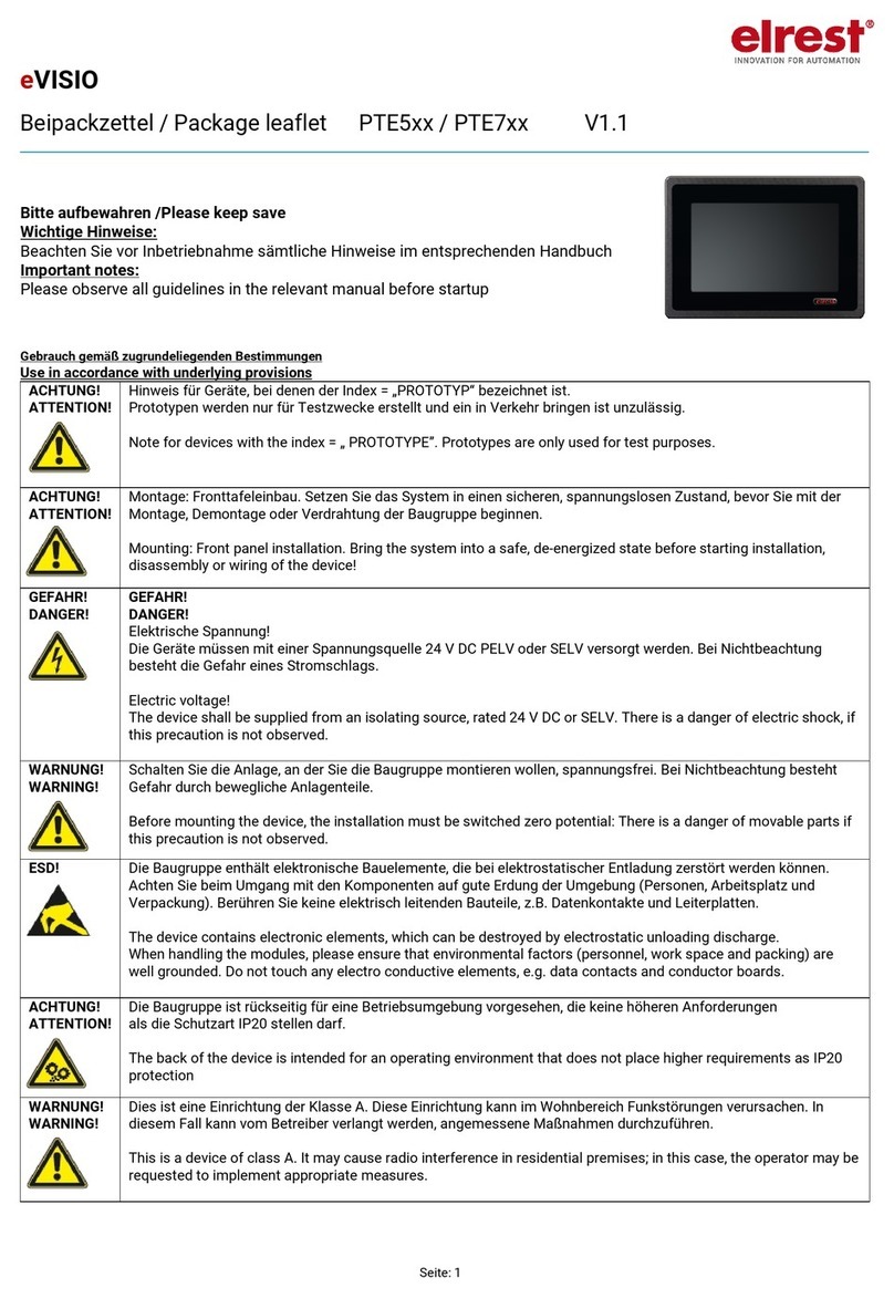
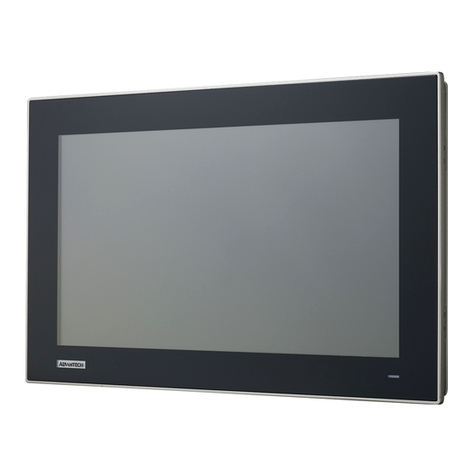
elrest eVISIO PTE715 Manual

Seite: 1
eVISIO
Beipackzettel / Package leaflet PTE5xx / PTE7xx V1.0
Bitte aufbewahren /Please keep save
Wichtige Hinweise:
Beachten Sie vor Inbetriebnahme sämtliche Hinweise im entsprechenden Handbuch
Important notes:
Please observe all guidelines in the relevant manual before startup
Gebrauch gemäß zugrundeliegenden Bestimmungen
Use in accordance with underlying provisions
ACHTUNG!
ATTENTION!
Hinweis für Geräte, bei denen der Index = „PROTOTYP“ bezeichnet ist.
Prototypen werden nur für Testzwecke erstellt und ein in Verkehr bringen ist unzulässig.
Note for devices with the index = „ PROTOTYPE”. Prototypes are only used for test purposes.
ACHTUNG!
ATTENTION!
Montage: Fronttafeleinbau. Setzen Sie das System in einen sicheren, spannungslosen Zustand, bevor Sie mit der
Montage, Demontage oder Verdrahtung der Baugruppe beginnen.
Mounting: Front panel installation. Bring the system into a safe, de-energized state before starting installation,
disassembly or wiring of the device!
GEFAHR!
DANGER!
GEFAHR!
DANGER!
Elektrische Spannung!
Die Geräte müssen mit einer Spannungsquelle 24 V DC PELV oder SELV versorgt werden. Bei Nichtbeachtung
besteht die Gefahr eines Stromschlags.
Electric voltage!
The device shall be supplied from an isolating source, rated 24 V DC or SELV. There is a danger of electric shock, if
this precaution is not observed.
WARNUNG!
WARNING!
Schalten Sie die Anlage, an der Sie die Baugruppe montieren wollen, spannungsfrei. Bei Nichtbeachtung besteht
Gefahr durch bewegliche Anlagenteile.
Before mounting the device, the installation must be switched zero potential: There is a danger of movable parts if
this precaution is not observed.
ESD!
Die Baugruppe enthält elektronische Bauelemente, die bei elektrostatischer Entladung zerstört werden können.
Achten Sie beim Umgang mit den Komponenten auf gute Erdung der Umgebung (Personen, Arbeitsplatz und
Verpackung). Berühren Sie keine elektrisch leitenden Bauteile, z.B. Datenkontakte und Leiterplatten.
The device contains electronic elements, which can be destroyed by electrostatic unloading discharge.
When handling the modules, please ensure that environmental factors (personnel, work space and packing) are
well grounded. Do not touch any electro conductive elements, e.g. data contacts and conductor boards.
ACHTUNG!
ATTENTION!
Die Baugruppe ist rückseitig für eine Betriebsumgebung vorgesehen, die keine höheren Anforderungen
als die Schutzart IP20 stellen darf.
The back of the device is intended for an operating environment that does not place higher requirements as IP20
protection
WARNUNG!
WARNING!
Dies ist eine Einrichtung der Klasse A. Diese Einrichtung kann im Wohnbereich Funkstörungen verursachen. In
diesem Fall kann vom Betreiber verlangt werden, angemessene Maßnahmen durchzuführen.
This is a device of class A. It may cause radio interference in residential premises; in this case, the operator may be
requested to implement appropriate measures.

Seite: 2
Mechanische Montage
Mechanical mounting
Gerät
Device
Einbaulage
Mounting position
eVISIO
horizontal
horizontal
diagonal
diagonal
vertikal
vertical
PTE5xx
PTE7xx
oder /or
0 °C … 45 °C
0 °C … 45 °C
0 °C … 45 °C
Zulässige Lagerungstemperatur
Permissible storage temperature
−20 °C ... +70 °C
Relative Luftfeuchtigkeit (ohne Betauung)
Permissible relative humidity
(noncondensing)
10 % ... 85 %
Betriebshöhe
Operating height
0 m … 2000 m
Anzahl der Klemmblöcke
Number of the terminal blocks
PTE507 4 (1x MB225-8)
PTE510 8 (1x MB225-4)
PTE715: 10 (1x MB225-8, 1 x MB225-3)
Montage:
Assembly Instruction:
Wandhalter
Wall bracket
Einsetzen
Inserting
Einrasten
Snapping
Demontage:
Disassembly Instruction:
Die Demontage erfolgt in umgekehrter Reihenfolge wie die Montage.
Disassembly occurs in the opposite way like assembly.
Anschlußbelegung
Terminal assignments
X1 : Spannungsversorgung
Power supply
Über diesen Steckverbinder wird das control Panel mit der Betriebsspannung versorgt. Der Anschluss ist gegen eine
Verpolung geschützt.
Die Speisung muss aus Netzteilen der Sicherheitsklasse SELV / PELV erfolgen.
The panel will be supplied via this plug connector. The connection is protected against polarity.
The supply shall be powerd from power supply units of the safty class SELV / PELV.

Seite: 3
Schnittstelle X1
Interface X1
PIN
Belegung
Allocation
Funktion
Function
1 2
3
1
2
3
24VDC
0 VDC
FE
Versorgungsspannung (18VDC …. 30VDC) / Imax
1A
24 VDC Power supply (18VDC …. 30VDC) /
Imax 1A
(GND –Bezugspotential Masse)
(GND –refererence potential)
FE Funktionserde
FE function earth
X2 Gigabit Ethernet Schnittstelle
Gigabit ethernet interface
Die Schnittstelle ist als RJ45-Buchse ausgeführt.
Die integrierte 100/1000 MBit Ethernet-MAC / -PHY unterstützt Auto –MDI(X).
Die Anschlüsse und Leitungen entsprechen CAT 5 und den Richtlinien für Ethernet Schnittstellen.
Für die Verbindung wird ein Patch Kabel verwendet.
The interface is executed as a RJ45 socket.
The integrated 100/1000 MBit Ethernet-MAC / -PHY supports Auto –MDI(X).
The connections and the cables acc. CAT 5e and the guidelines for ethernet interfaces.
For the connection will be use a patch cable.
Schnittstelle X2
Interface X2
PIN
Belegung
Allocation
Funktion
Function
Kabelfarbe
Cable colour
PIN1
1
TX+_D1
Transmit Data +
Weiß / orange White / Orange
2
TX-_D1
Transmit Data -
Orange Orange
3
RX+_D2
Receive Data +
Weiß / grün White / Green
4
BI+_D3
Bi-directional+
Blau Blue
5
BI-_D3
Bi-directional-
Weiß / blau White / Blue
6
RX-_D2
Receive Data -
Grün Green
7
BI+_D4
Bi-directional+
Weiß / braun White / Brown
8
BI-_D4
Bi-directional-
Braun Brown
X3 USB 2.0 Host Schnittstelle
USB 2.0 Host interface
Diese Schnittstelle ist als USB 2.0-Host Schnittstellen mit Typ-A-Buchse ausgeführt.
Die Stromversorgung kann max. 500 mA betragen und ist durch Überstromerkennung abgesichert.
Der Anschluss für diese Schnittstelle entspricht der USB-Spezifikation 2.0 High-Speed, maximale Übertragungsrate: 480
MBit/s.
Die folgende Tabelle und Abbildung geben Auskunft über die Pinbelegung dieser Schnittstellen
The interface is executed as a USB 2.0-Host interface with Type A socket.
Power supply is max. 500 mA and is fused by overcurrent detection.
The connection for this interface acc. the USB-specification, 2.0 High-Speed, max. transmission rate: 480 MBit/s.
The follwing table and illustration shows the pin assignment of this interface.
Schnittstelle X3
Interface X3
PIN
Belegung
Allocation
Funktion
Function
1
USB_VCC1
USB + 5 VDC
2
USB_N
USB Datenleitung D-
USB data line D-
3
USB_P
USB Datenleitung D+
USB data line D+
4
USB_GND
USB GND

Seite: 4
S2 Taster „SLEEP / RESET“
Key „SLEEP / RESET“
Die Taste S2 hat folgende Funktion:
The S2 key has the following function
Betätigung >8 sec: Auslösen eines RESET an der CPU mit Warm-Boot Funktion;
Activity >8 sec: innerhalb der Warm-Boot-Phase wird das Gerät neu gestartet.
Activity >8 sec: Triggering a RESET on the CPU with a warm boot function;
within the warm boot phase the device is restarted.
S3 Taster „INT“
Key „INT“
Der Taster ist aktuell ohne Funktion.
The key is actually without function
Batteriefach
Battery compartment
Die genaue Handhabung ist beschrieben im Kapitel “Pufferbatterie wechseln”in der Gerätebeschreibung.
The exact handling is described in the chapter “Changing backup battery” in the device description.
Haben Sie Fragen, Wünsche oder Anregungen?
Nehmen Sie Kontakt mit uns auf:
Umfassende Informationen zu elrest unter: www.elrest.de
Ihr direkter Draht zu elrest: +49 (0) 7021-92025-0
elrest Automationssysteme GmbH • Leibnizstraße 10 • D-73230 Kirchheim unter Teck
© 2017 Abbildungen und Beschreibungen sowie Abmessungen und technische Daten entsprechen den Gegebenheiten oder Absichten zum Zeitpunkt des Druckes dieses Prospektes.
Änderungen jeder Art, insbesondere soweit sie sich aus technischem Fortschritt, wirtschaftlicher Ausführung oder ähnlichem ergeben, bleiben vorbehalten.
Other manuals for eVISIO PTE715
2
This manual suits for next models
4
Other elrest Industrial Monitor manuals
