Elsema MD12-2 User manual

ELSEMA
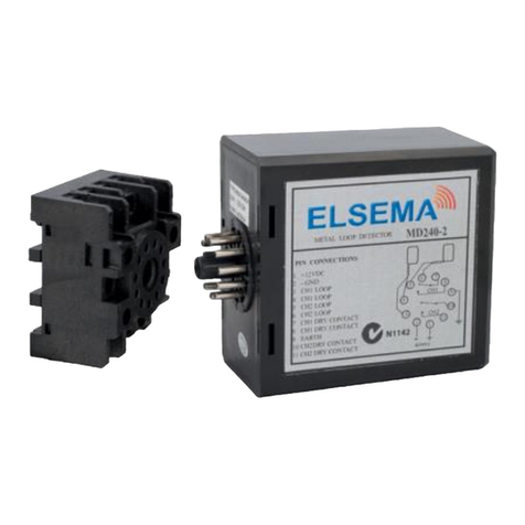
MD12-2 Metal Loop Detector
- 1 -
MD12-2
Metal Loop Detector
Features
Supply 12VDC
Adjustable sensitivity (8 levels via dip switch)
2 x Relay outputs (each can be configured individually)
Power up and loop activation LED indicator.
Industry standard 11-way plug-in type circular connector.
Two loop detection function CH1 (10 way dip switch) and CH2
(7 way dip switch).
Application
Controls automatic doors or gates when a vehicle is present source.
Description
Loop detectors in recent years have become a popular tool having innumerable applications in policing, right
from surveillance operations to traffic control. Automation of gates and doors has become a popular usage of the
loop detector.
The digital technology of the loop detector enables the equipment to sense a change in the inductance of the
loop as soon as it detects the metal object in its path. The inductive loop which detects the object is made of
insulated electrical wire (32/020; 32 Strand, 2mm diameter) and is arranged either as a square or rectangle shape.
The loop consists of several loops of wire and consideration should be giving to the loop sensitivity when
installing on different surfaces. Setting the correct sensitivity allows the loop to operate with maximum
detection (8 levels via dip switch settings). Channel 1, is set by the 10 way dip switch and channel 2 is set by 7
way dip switch. When detection occurs, the detector energises 2 relays for the output (each can be configured
individually). This energising of the relay can be configured into different modes, by selecting the respective
dipswitch.
Technical Data
Supply voltage 12VDC
Standby Current 54 mA
Operating Current 73 mA
Outputs 2 changeover relays rated at 240VAC, 3A
Connection Screw type terminal

ELSEMA
MD12-2 Metal Loop Detector
- 2 -
Connections
Both loops have to be connected in order for the MD240-2 to work.
Sensitivity Selection
Sensitivity and frequency of the loop can be adjusted by 7-way dip switch and 10-way dip switch setting. User
can select 8 different setting by changing the setting of the dip-switch to different modes as in the dip-switch
setting tables below. Dip switch 6, 7 and 8 for CH1 sensitivity selection with 0.8 being the least sensitive and
0.015 being the most sensitive. Dip switch 3, 4 and 5 for CH2 sensitivity selection with 0.8 being the least
sensitive and 0.015 being the most sensitive.
Dipswitch Settings
Switch 1: Channel 1 Loop Function Selection (10 way dip switch)
Dip switch Settings
1 of CH1 Function
Special Sensitivity Increase For Both Trailer (Both Channels)
Dip switch
1 is ON
Increase sensitivity for both channel to avoid unwilling relay Off for
leaving especially for trailer
Pin Type
1 12VDC+
2 12VDC-
3 CH1 Loop
4 CH1 Loop
5 CH2 Loop
6 CH2 Loop
7 CH1 Dry Contact
8 CH1 Dry Contact
9 Earth
10 CH2 Dry Contact
11 CH2 Dry Contact

ELSEMA
MD12-2 Metal Loop Detector
- 3 -
Dip switch Settings
2 of CH2 Function
Automatic Reset (Both Channels)
Dip switch
2 is ON
Vehicle can be permanently present. (no auto-reset, unless vehicle
has left or manual reset)
Dip switch
2 is OFF
Normal mode, (automatic reset after 10minutes present of vehicle,
used to solve the mistake operation. recommended).
Dip switch Settings
3 of CH1 Function
Special Functions
Dip switch
3 is ON
Direction Detection. (If vehicle is from CH1 to CH2, then CH1
relay should be used; if vehicle is from CH2 to CH1, then CH2
relay should be used).
Dip switch
3 is OFF
Normal mode, Each loop activates respective relay.
Dip switch Settings
4 of CH1 Function
Special Functions
Dip switch
4 is OFF
CH1 relay will be present output
Dip switch
4 is ON
CH1 relay output type is pulse

ELSEMA
MD12-2 Metal Loop Detector
- 4 -
Dip switch Settings
5 of CH1 Function
Special Functions
Dip switch 5 is
OFF
When vehicle goes in, CH1 relay is in pulse output for
200ms
Dip switch 5 is
ON
When vehicle has left the loop, CH1 relay will give a pulse
output for 600ms after a delay of 200ms
Dip switch Settings
6, 7 and 8 of CH1 Sensitivity (%)
Sensitivity Selection. (Eight Levels Choices)
Dip switch 6,7
and 8 is ON
0.015 (highest sensitivity range)
Dip switch 6
and 7 is ON
0.02
Dip switch 6
and 8 ON
0.04
Dip switch 6 is
ON
0.08
Dip switch 7
and 8 is ON
0.12
Dip switch 7 is
ON
0.2
Dip switch 8 is
ON
0.5
Dip switch 6,7
and 8 is OFF
0.8 (lowest sensitivity range)

ELSEMA
MD12-2 Metal Loop Detector
- 5 -
Dip switch 9 and 10 of CH1
Frequency
Frequency (30 K to 100 KHz). Used to avoid the interference
Dip switch 9 and 10
is OFF
High
Dip switch 9 is ON
Medium-High
Dip switch 10 is ON
Medium-Low
Dip switch 9 and 10
is ON
Low
Switch 2: Channel 2 Loop Function Selection (7 way dip switch)
Dip switch 1 of CH2 Function
Relay Output Type Selection
Dip switch 1 is OFF
CH2 relay will be present output
Dip switch 1 is ON
CH2 relay output type is pulse
Dip switch 2 of CH2 Function
Relay Pulse Output Type Selection
Dip switch 2 is OFF
When vehicle goes in, CH2 relay is in pulse output for
200ms
Dip switch 2 is ON
When vehicle has left the loop, CH2 relay will give a
pulse output for 600ms after a delay of 200ms

ELSEMA
MD12-2 Metal Loop Detector
- 6 -
Dip switch 3, 4 and 5 of CH2 Function
Sensitivity Selection
Dip switch 3, 4 and
5 is ON
0.015 (highest sensitivity range)
Dip switch 3 and 4 is
ON
0.02
Dip switch 3 and 5 is
ON
0.04
Dip switch 3 is ON
0.08
Dip switch 4 and 5 is
ON
0.12
Dip switch 4 is ON
0.2
Dip switch 5 is ON
0.5
Dip switch 3, 4 and
5 is OFF
0.8 (lowest sensitivity range)

ELSEMA
MD12-2 Metal Loop Detector
- 7 -
Dip switch 6 and 7 of CH2 Function
Frequency Selection
Dip switch 6 and 7 is
OFF
High
Dip switch 6 is ON
Medium-High
Dip switch 7 is ON
Medium-Low
Dip switch 6 and 7 is
ON
Low
Setup Instructions
Power Led
RED power LED indicates “Power ON”
Detecting Led
Continuously On: Indicates vehicle detection.
Blinking slowly: Indicates loop is short circuit or the number of twists after the loop is not enough.
Blinking fast: Indicates loop is open circuit or too many twists after the loop.
Power : Red Led
If it is fully lit, power is supplied.
Green Led
CH1 If it is fully lit, a vehicle is detected on loop 1. If it blinks, then loop 1 is
faulty.
CH2 If it is fully lit, a vehicle is detected on loop 2. If it blinks, then loop 2 is
faulty

ELSEMA
MD12-2 Metal Loop Detector
- 8 -
Sensitivity Selection
*In the application, where two or more loop detectors and sensing loops have been installed, set one detector to
high frequency and the other set to low frequency to minimize the effects of cross-talk between the two systems
(The sensing loops and detectors should be positioned at least 2m apart).
Reset Button: Please note: The MD12-2 must be reset every time a setting change is made to the Dip-switches

ELSEMA
MD12-2 Metal Loop Detector
- 9 -
LOOP
Elsema stocks pre-made loops for easy installation. Our pre-made loops are suitable for all types of installations.
Either for cut-in, concrete pour or direct hot asphalt overlay.
see www.elsema.com/auto/loopdetector.htm
Loop1200 : 1.2 x 1.2 metres -- 3 metres Lead-in plus 3 metres twisted wire.
Loop1500 : 1.5 x 0.8 metres -- 3 metres Lead-in plus 3 metres twisted wire.
Loop2000 : 2.0 x 1.2 metres -- 3 metres Lead-in plus 3 metres twisted wire.
We can also make custom size loops. Please contact us for your custom loop size.
Detector position and installation
Install the detector in a weatherproof housing.
The detector should be as close to the sensing loop as possible.
The detector should always be installed away from strong magnetic fields.
Avoid running high voltage wires near the loop detectors.
Do not install the detector on vibrating objects.
When the control box is installed within 10 metres of the loop, normal wires can be used to connect the
control box to the loop. More than 10 metres requires the use of a 2 core shielded cable. Do not exceed
30 metres distance between control box and loop.
Troubleshooting
Symptoms Solution
If the detector is not working Press reset
If red led indicator is not fully lit Check for power supply
If green led
indicator:
Blinks slowly It maybe because the loop is short circuit or the no: of turns is not
enough.
Blinks faster It maybe because the loop is open or the no: of turns is too many.
If no: of turns is not enough Lower the frequency (if the frequency is still too high, you must add
more turns).
If no: of turns is too many Higher the frequency (if the frequency is still too low, you must
remove some turns).
Manufactured by
Elsema Pty Ltd
31 Tarlington Place, Smithfield
NSW 2164, Australia
Ph: 02 9609 4668
Fax: 02 9725 2663
Website: http://www.elsema.com
Distributed by
Table of contents
Other Elsema Security Sensor manuals
