Elsist MISSION 1000 User manual
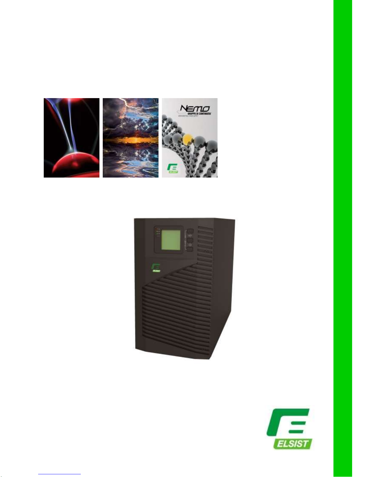
Uninterruptible Power Systems
Mission 1K-2K-3K
Single Phase UPS
INSTRUCTION MANUAL

MISSION 1K●2K●3K
SINGLE PHASE
Rev. 02 –19 March 2015 2
Contents
1.Safety instruction........................................................................................................................................3
1.1 Safety instruction...................................................................................................................................3
1.2 Symbols indication ................................................................................................................................3
2.Product Introduction...................................................................................................................................4
2.1 The appearance of the product.............................................................................................................4
2.2 The principle of the product...................................................................................................................5
2.3 Model.....................................................................................................................................................5
3.Installation....................................................................................................................................................6
3.1 Unpacking and inspection.....................................................................................................................6
3.2 Notes.....................................................................................................................................................6
3.3 UPS input connection............................................................................................................................6
3.4 UPS output connection .........................................................................................................................6
3.5 Long backup external battery connection.............................................................................................7
4.Panel display,operation and running........................................................................................................8
4.1 Faceplate display illumination...............................................................................................................8
4.2 Operation.............................................................................................................................................10
4.3 Parameter setting................................................................................................................................11
4.4 Parameters inquiring...........................................................................................................................17
4.5 Run mode............................................................................................................................................18
5.Maintenance...............................................................................................................................................20
5.1 Battery Maintenance...........................................................................................................................20
6.Troubleshooting and performance of product.......................................................................................20
6.1 LED indication and warning table.......................................................................................................21
6.2 Troubleshooting...................................................................................................................................22
6.3 EMC standard/Safety standard...........................................................................................................23
6.4 Product Performance..........................................................................................................................23
6.5 Communication interface ....................................................................................................................25
Manual instruction
Thanks for purchasing our UPS, it is safe and reliable, so few maintenance is required.
Read this manual carefully and completely. It includes instructions of safety installation and operation. They will help your UPS obtain
the longest life and service. This manual accounts the internal working principle and the relative protection functions. This manual also
contains information about the usage of the equipment.
Please obey the instructions and all the warning stated in the manual or on the machine. Don’t operate the machine before finishing
reading the safety and operation instructions.
Note: Because of the continuous improvements, our products may differ somewhat from the contents included in this manual. You can
contact local office to get the information when necessary.

MISSION 1K●2K●3K
SINGLE PHASE
Rev. 02 –19 March 2015 3
1. SAFETY INSTRUCTION
This chapter mainly introduce the safety marks and notes of MISSION 1KVA-2KVA-3KVA series on-line UPS.
Read this chapter carefully before operating on the equipment.
1.1 Safety instruction
There is dangerous voltage and high temperature inside the UPS. During the installation, operation and
maintenance, please abide the local safety instructions and relative laws, otherwise it will result in personnel
injury or equipment damage. Safety instructions in this manual act as a supplementary for the local safety
instructions.
Our company will not assume the liability that caused by disobey of safety instructions. Please note the
following:
1. Don’t use the UPS when the actual load exceeds the rated load.
2. There are high-capacity batteries in the standard type UPS. You mustn’t open the enclosure or it will lead to
electric shock. If it needs internal maintenance or battery replacement, please send it to the designated site.
3. Internal short-circuit of the UPS will cause electric shock or fire. So don’t place the containers equipped with
liquid on the top of the UPS so as not to cause danger of electric shock and so on.
4. Don’t put the UPS in a place with high temperature or humidity as well as the corrosive gas, much dust.
5. Keep good air circulation between in-vent on front panel and out-vent on back panel.
6. Avoid direct sunlight or near heat-dispensed objects.
7. In case that the smoke appears on the UPS, please cut off the power as soon as possible and contact the
dealer service site.
1.2 Symbols indication
The safety symbols cited in this manual are shown in table 1-1, which are used to inform readers of safety
issues that should be obeyed when installation, operation and maintenance.
Safety Symbol
Indication
Attention
Static discharge sensitive
Electric shock
Table 1-1
There are three levers of safety grade: Dangerous, Warning and Attention. The remark is on the right side of the
safety symbol, the detailed comments is behind, shown as following:
Dangerous: Indicate risk of serious injury or death or seriously damage the equipment
Warning: Indicate risk of serious injury or damage the equipment.
Attention: Indicate risk of injury or damage the equipment.

MISSION 1K●2K●3K
SINGLE PHASE
Rev. 02 –19 March 2015 4
2. PRODUCT INTRODUCTION
2.1 The appearance of the product
Fig. 1 Front Panel view Fig. 2 1KVA Rear Panel view
Fig. 3 2KVA Rear Panel view Fig. 4 3KVA Rear Panel view

MISSION 1K●2K●3K
SINGLE PHASE
Rev. 02 –19 March 2015 5
2.2 The principle of the product
Fig 5 UPS Principle Diagram
1.Input filter: Complete filtering the input AC utility power to provide the clean power for UPS.
2.AC/DC converter: Convert the filtered AC mains to DC and boost the DC for DC/AC inverter.
3.DC/DC booster: When the UPS works in battery mode, the circuit boosts the DC for DC/AC inverter.
4. DC/AC inverter: Convert the boosted DC to stable AC output.
5.Bypass: When overload or failure of inverting happen in the UPS, it transfers to bypass mode to supply power
to loads.
6.Charger: Standard unit provides 1A; long backup unit provides 7A.
7. Battery: Sealed Lead Acid Battery.
8.Output filter: Complete filtering the output of the UPS to provide the clean power for loads.
2.3 Model
UPS sort
MODEL NO
Remark
Standard unit
1KVA
Internal 1A charger, 2 PCS 7AH batteries
2KVA
Internal 1A charger, 4 PCS 7AH batteries
3KVA
Internal 1A charger, 6 PCS 7AH batteries
Long backup unit
1KVA
★internal 6A charger, external 24V battery
2KVA
★internal 6A charger, external 48V battery
3KVA
★internal 6A charger, external 72V battery
The 12V/9AH battery which is sealed lead acid maintenance free can be chosen as internal battery of the
standard unit.
The 7A charger can be chosen as internal charger of the long backup unit.
Two internal chargers can be used in long backup unit.
MISSION 1K●2K●3K
SINGLE PHASE
Rev. 02 –19 March 2015 6
3. INSTALLATION
3.1 Unpacking and inspection
1. Unpacking the box and check the UPS. If damaged or some parts missing, don’t start the machine and
inform your supplier.
2. Check the box content (please consult Box Content Table).
3. Check if the UPS is that you wanted to purchase. You can verify it on the label on the rear panel of the
UPS.
3.2 Notes
1. Please place the UPS in a clean, stable environment, avoid the vibration, dust, too humidity, flammable gas
and liquid, corrosive.
2. The ambient temperature around UPS should keep in a range of 0°C~40°C. If UPS works above 40°C, it
is required that the rated value of the largest load decreases 12% while the temperature increases every
5°C . The highest temperature cannot be more than 50°C when UPS works.
3. UPS should be placed in a sufficiently ventilated place.
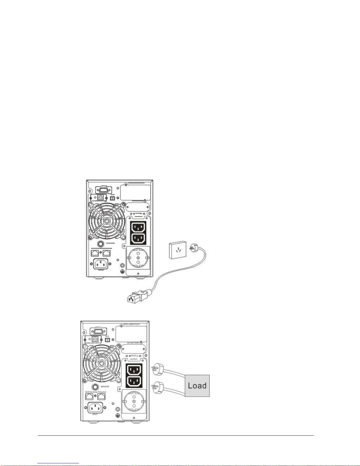
3.3 UPS input connection
Connect the UPS to the mains by input power cable which is equipped with the UPS.
Fig 6 Input Connection
3.4 UPS output connection
Fig 7 Output connection

MISSION 1K●2K●3K
SINGLE PHASE
Rev. 02 –19 March 2015 7
3.5 Long backup external battery connection
Fig 8 Battery connection
Warning:
★Before installing battery, make sure that UPS and breaker are all turned off. Remove all your metallic
adornment such as finger ring, watch, and so on before connecting battery.
★No anti-connection or short circuit between the battery anode and cathode forever. Red cable connect with
battery anode “+” and black cable connect with cathode “-”.
★Please use the screwdriver with insulating handle. Do not lay the tools or metallic goods on the battery.
Notice:
★When using the external battery, It is best to use external battery cable which matches with the equipment.
★When connecting load to UPS, first turn off load and then connect the power cable and finally turn on load
one-by-one.
★Inductance loads such as motor, fluorescent lamp, photocopier are strictly prohibited connecting to UPS to
avoid damage.
★Plug UPS on the special socket with over-current protection, the power socket that used should be
connected with ground wire.
★UPS is likely to have output voltage no matter whether the power input cable is plugged in mains input
socket. If you wish UPS have no output, first break off the switch and then cancel the mains.
★When connect laser printer, select the capacity of UPS according to the UPS start power because the startup
power is higher.

MISSION 1K●2K●3K
SINGLE PHASE
Rev. 02 –19 March 2015 8
4. PANEL DISPLAY, OPERATION AND RUNNING
The operation is simple, operators only need to read the manual and follow the operation instructions listed in
this manual without any special training.
4.1 Faceplate display illumination
4.1.1 Keys function
Fig. 9 Front panel buttons instruction
ON key +
Press and hold this key for more than half a second to turn on the UPS.
OFF key +
Press and hold this key for more than half a second to turn off the UPS.
TEST/MUTE key +
Press and hold the key for more than 1 second in Line mode or economical mode: UPS runs the self-test
function.
Press and hold the key for more than 1 second in battery mode: UPS runs the mute function.
INQUIRING key or
Non-function setting mode:
Press and hold the key for more than half a second (less than 2 seconds): Indicate the items of the LCD item
section orderly.
Press and hold this key for more than 2 seconds: Circularly and orderly display the items every 2 seconds,
when press and hold the key for some time again, it will turn to output status.
Function setting mode:
Press and hold the key for more than half a second (less than 2 seconds): Select the set option.
FUNCTION SETTING key
Non-function setting mode:
Press and hold the key for more than 2 seconds: Function setting interface.
Function setting mode:
Press and hold the key for more than half a second (less than 2 seconds): Affirm the set option.
Press and hold the key for more than 2 seconds, exit from this function setting interface.

MISSION 1K●2K●3K
SINGLE PHASE
Rev. 02 –19 March 2015 9
4.1.2 The function of LED indicators
Warning red LED is on: UPS is fault. For example: Overload beyond the allowed time, inverter fault, BUS
fault, over temperature fault etc.
Bypass yellow LED is on: UPS is alarming. For example: Bypass mode supply power and etc.
Battery yellow LED is on: UPS is alarming. For example: Battery mode supply power and etc.
Inverter green LED is on: UPS is normally powered by mains or ECO mode or battery mode.
After starting the UPS, the four LEDs will light and go out one-by-one. It circulates several times until starting the
UPS successful.
NOTE: As to the LED indication in different modes, please refer to the LED display panel and warning table.
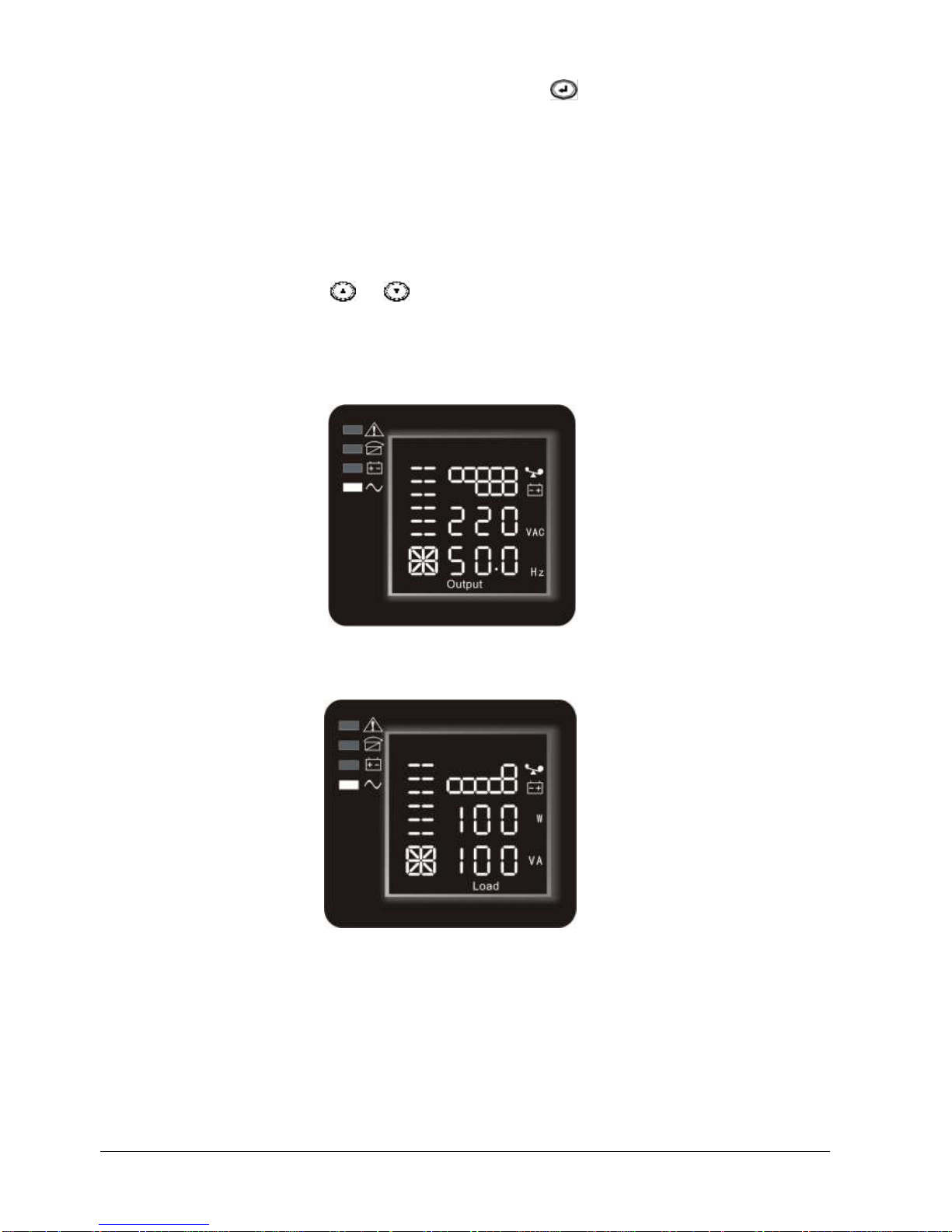
4.1.3 LCD display functions
The LCD displays as following picture
LCD display comprises numerical value section, capacity graphics section, fan-status graphics section and
charger-status graphics section.
Numerical value section: display the corresponding numerical value of inquiring items(output, load,
temperature, input, battery), for example, as the graphics shows above, the
output voltage is 220v, the output frequency is 50Hz.
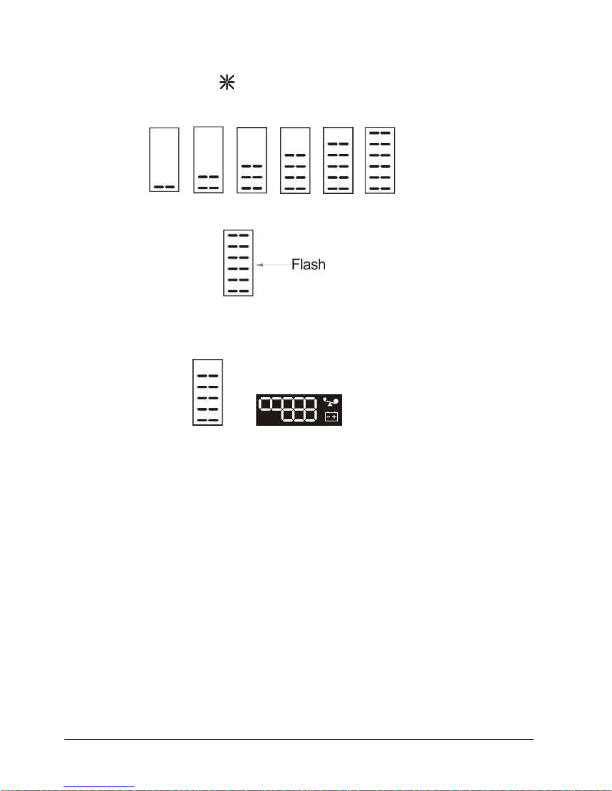
Capacity graphics section: display the capacity of the battery and load. Every pane represents 20%
capacity. As graphics showed above, the capacity of the battery is 80%
-100%( 5 panes), the load reaches 40%-60%(3 panes). When UPS is
overload, the icon will flash, when capacity of battery is too low or
disconnected, the icon will also flash.
MISSION 1K●2K●3K
SINGLE PHASE
Rev. 02 –19 March 2015 10
Fan-status graphics section: display if the fan works normally. When the fan works normally, it will show
the dynamic fan blades rotating; when the fan works abnormally, the icon
will keep on flashing with the warning.
Charger-status graphics section: display the status of the charger. When charger works normally, the
corresponding icon will vary dynamically and orderly, just as graphics (1)
graphics (1)
when charger works abnormally, the icon will flash in a whole, as graphics (2):
graphics (2)
When UPS is in battery mode, the number of the icons of the charger-state section will vary according to the
changeable capacity of the battery (pane). For example, there are five panes in picture below, (as the right
picture of the graphics (3)), so the corresponding number of icons is five rows (as the left picture of the graphics
(3)), followed by this rule
graphics (3)
4.2 Operation
4.2.1 Turn on operation
Turn on the UPS in line mode
1 Once mains power is plugged in, the UPS will charge the battery, at the moment, LCD shows that the
output voltage is 0, which means UPS has no output. If it is expected to have output of bypass, you can set
the bps “ON” by LCD setting menu.
2 Press and hold the ON key for more than half a second to start the UPS, then it will start the inverter.
3 Once started, the UPS will perform a self-test function, LED will light and go out circularly and orderly.
When self-test finishes, it will come to line mode, the corresponding LED lights, UPS is working in line
mode.
Turn on the UPS by DC without mains power
1 When mains power is disconnected, press and hold the ON key for more than half a second to start UPS.
2 The operation of UPS in the process of start is almost the same as that when mains power is in. After
finishing the self-test, the corresponding LED lights and UPS is working in battery mode.
4.2.2 Turn off operation
Turn off the UPS in line mode
1 Press and hold the OFF key for more than half a second to turn off the UPS and inverter.
2 After UPS shutting down, LED go out and there is no output. If output is needed, you can set bps “ON” on
LCD setting menu.
Turn off the UPS by DC without mains power
1 Press and hold the OFF key for more than half a second to turn off the UPS.
MISSION 1K●2K●3K
SINGLE PHASE
Rev. 02 –19 March 2015 11
2 When turning off the UPS, it will do self-testing firstly. LED light and go out circularly and orderly until there
is no display on the panel.
4.2.3 UPS self-test/mute test operation.
1 When UPS is in line mode, press and hold the self-test/mute key for more than 1 second, LEDs light and
go out circularly and orderly. UPS comes to self-test mode and tests its status. It will exit automatically after
finishing testing, LED resume.
2 When UPS is in battery mode, press and hold the self-test/mute key for more than 1 second, the buzzer
stops beeping. If you press and hold the self-test/mute key for one more second, it will restart to beep
again.
4.3 Parameter setting
UPS has setting function. It can run the setting on any mode. After setting, it will become effective at once when
meets some standards. The set information can be saved only when the battery connected and normally turning
off the UPS.
The operation of setting is as following:
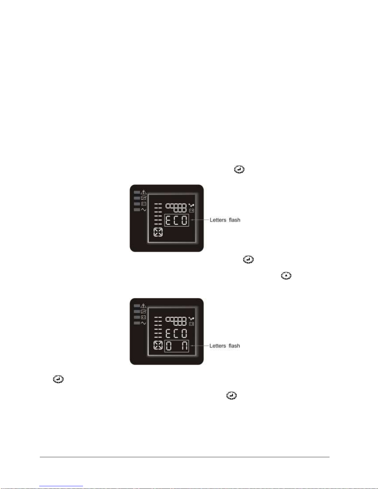
4.3.1 ECO mode setting
1 Enter the setting interface. Press and hold the function setting key for more than 2 seconds, then
come to setting interface, the letters “ECO” will flash as following:
2 Enter the ECO setting interface. Press and hold the function setting key for more than half a second
(less than 2 seconds), then come to setting interface of ECO, at this time, the letters “ECO” will light for a
long time. The “ON”(or OFF) below the ECO will flash. Press and hold the inquiring key for more than
half a second (less than 2 seconds) to determine whether the ECO function is used or not. If used, the
corresponding word is “ON”, if not, the word is “OFF”. It can be determined by yourself.
3 Confirm the ECO selecting interface. After selecting ON or OFF, press and hold the function setting key
for more than half a second (less than 2 seconds). Now, the ECO setting function is completed and
the “ON” or “OFF” below the “ECO” will light without flash.
4 Exit from the setting interface. Press and hold function setting key for more than 2 seconds, exit from
he setting interface and turn to main interface.
MISSION 1K●2K●3K
SINGLE PHASE
Rev. 02 –19 March 2015 12
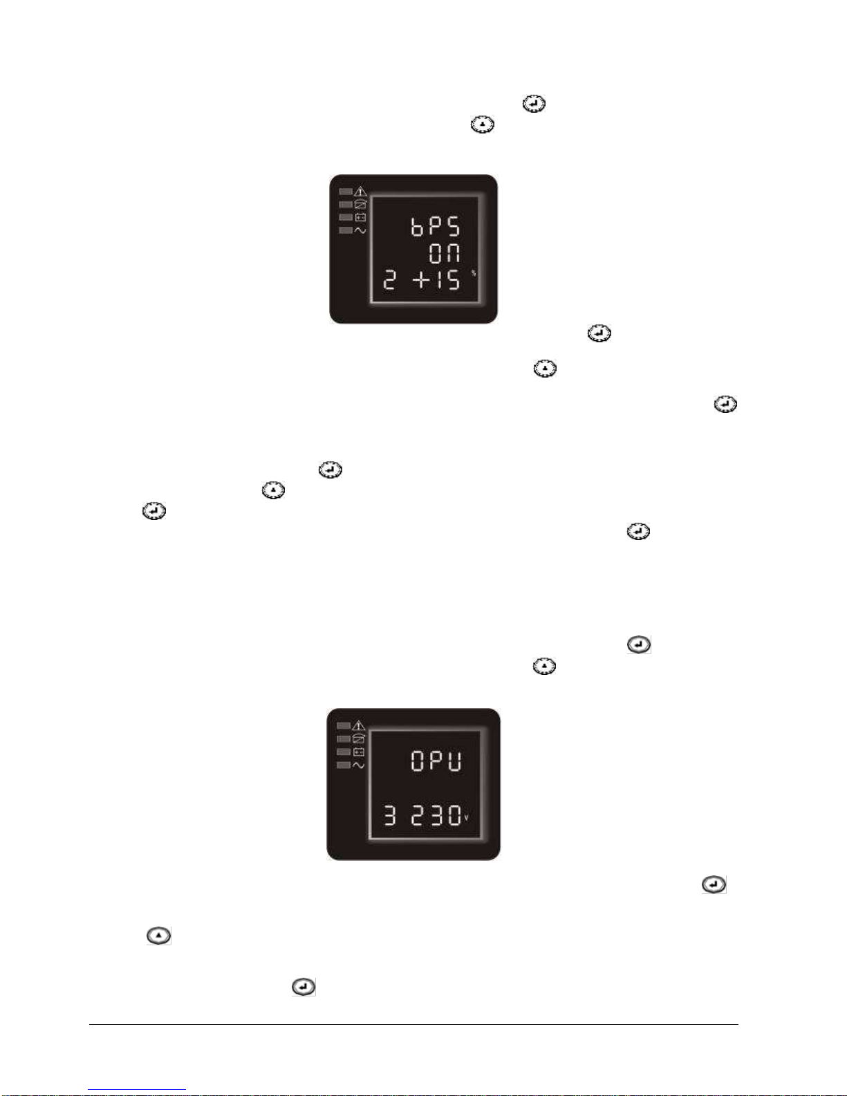
4.3.2 Output on bypass mode setting (bPS)
1 Enter the setting interface. Press and hold the function setting key for more than 2 seconds, then
come to setting interface, Press and hold the function setting key for more than half a second (less than 2
seconds), select the function setting, choose the auto battery test setting interface, at the moment, the letters
“ABT” will flash as following:
2. Enter the Output on bypass interface: Press and hold the configuration key for more than half a
second (less than 2 second), and enter in bPS configuration interface, now “bPS” letters will remain fix.
and “ON” (or OFF) letters below bPS will be flashing. Press key to select ON or OFF. If bPS
function must be used, then select “ON”, otherwise select “OFF” if you don’t intend to use this function.
3 Confirm the bPS setting interface: After having selected either ON or OFF, press configuration key
for more than half a second (less than 2 second) to confirm the choice. Now config of bPS function is
completed and “ON” or “OFF” letters below “bPS” will remain fixed.
4 4 Select the Voltage Range of the bPS function: after selecting ON press the key for more than half
second (less than 2 seconds) and select the higher value 5%, + 10%, + 15%, + 25% ( default is +
25%) using the key , confirm by pressing for more than half second (less than 2 seconds) the key
, go to the lower value selection, proceed in the same way.
5 Exiting the Configuration Interface: Press and hold the Configuration Function key , for more than
2 seconds to exit this configuration interface and return to the Main Interface..
6 After configuring the bPS "ON", when the UPS is connected to the mains without turning it on, the
output voltage is fed through the bypass.
4.3.3 Ouput Voltage selection function setting (OPU)
1 To enter the configuration interface, press and hold the Configuration function key for more than
2 seconds, then access the Configuration Interface. Press the key until you reach the OPU menu
(3), the word "OPU" flashes:
2 Start the Output Voltage selection mode interface: Press and hold the configuration function key
for more than half second (less than 2 seconds), the OPU configuration output interface is accessed,
at this point the write "OPU" will remain fixed. The numeric value under OPU will blink. Press the key
to select the numeric value of the desired "OPU" function (output voltage). Selectable voltages
are 208V, 220V, 230V, 240V, (the default is 220V).
3. Confirm the Output Voltage selection mode interface. After selecting the numeric value, hold down the
function configuration key for more than half a second (less than 2 seconds). Now, the "OPU"
mode configuration is completed and the numeric value under "OPU" will remain fixed.

MISSION 1K●2K●3K
SINGLE PHASE
Rev. 02 –19 March 2015 13
4. Exit the configuration interface. Press and hold the button for more than 2 seconds to exit this
configuration interface to return to the main interface.
Note:
When configuring the output voltage, the load should be off or disconnected from the UPS.
4.3.4 Number and type of battery selection function (bAt)
1. To enter the configuration interface, press and hold the Configuration function key for more than 2
seconds, then access the configuration interface. Press the key until you reach the bAt menu (4),
the word "bAt" will flash:
2. Start the number and battery type selection interface: Press and hold the configuration function key
for more than half a second (less than 2 seconds), enter the bAt configuration interface, then "bAt" will
remain fixed and the word "ON" (or OFF) under bAt will blink. Press the key to select ON or OFF.
3. Confirm the bAt selection interface: After selecting ON or OFF, pressing the configuration function key
for more than half second (less than 2 seconds) confirms the selection. If OFF is selected, the
procedure ends and returns to the initial configuration. If ON is selected, the numeric value of the
additional battery cabinets is configured, select the value using the key , confirm by pressing for
more than half a second (less than 2 seconds) key , scroll to the battery type selection, select the
value using the key , confirm by pressing for more than half second (less than 2 seconds) the key
4. Exit the configuration interface: Press and hold the configuration function key for more than 2
seconds to exit this configuration interface and return to the Main Interface.
4.3.5 function setting (Seg)
1 To enter the configuration interface, press and hold the configuration function key for more than 2
seconds, then access the configuration iInterface. Press the key until you reach the Seg (5) menu,
the word "Seg" will blink:
The function is present in the menu but not available for the following models:
MISSION1000 - MISSION2000 - MISSION3000.

MISSION 1K●2K●3K
SINGLE PHASE
Rev. 02 –19 March 2015 14
4.3.6 Battery discharge time setting function (tod)
1. To enter the configuration interface, press and hold the configuration function key for more than 2
seconds, then access the Configuration Interface. Press the key until you reach the "tod" menu (6),
the word "tod" flashes:
2 Start the selection interface Battery discharge time setting: Press and hold the configuration function
key for more than half a second (less than 2 seconds), enter the "tod" configuration interface, at
this point the write "Tod" will remain fixed. The numeric value under the word "tod" will blink. Press the
key to select the desired option between 1m - 2m - 3m (default option) - 5m - 10m - 30m - 1h - 2h
- 3h - 4h - OFF (no time limitation).
3 Confirm the "tod" selection: After selecting the desired time, pressing the configuration function key
for more than half second (less than 2 seconds) confirms the selection. Now, the configuration of
the "tod" function is completed and the selection under "tod" will remain fixed.
4 Exit the Configuration Interface. Press and hold the configuration function key for more than 2
seconds to exit and return to the main interface.
5 When the "tod" function is activated, the Ups (in battery operation) will turn off at the end of the
selected time by powering off the connected devices.
4.3.7 Auto battery test function setting (Abt)
1 Enter the setting interface. Press and hold the function setting key for more than 2 seconds, then
come to setting interface, Press and hold the function setting key and select the menu bPS (2), the
letters “bPS” will flash as following:
2 Enter the auto battery test setting interface. Press and hold the function setting key for more than half
a second (less than 2 seconds), then come to setting interface of ABT, at this time, the letters “ABT” will
light for a long time. The “ON” below the ABT will flash. Press and hold the inquiring key for more than
half a second (less than 2 seconds) to determine whether the ABT function is used or not. If used, the
corresponding word is “ON”, if not, the word is “OFF”. It can be determined by yourself.

MISSION 1K●2K●3K
SINGLE PHASE
Rev. 02 –19 March 2015 15
3 Confirm the auto battery test setting interface. After selecting ON or OFF, press and hold the function
setting key for more than half a second (less than 2 seconds), Now, the ABT setting function is
completed and the “ON” or “OFF” below the “ABT” will light without flash.
4 Exit from the setting interface. Press and hold function setting key for more than 2 seconds, exit from
the setting interface and return to main interface.
5 When the ABT function is set to ON , the UPS will automatically do battery test every 30 days for 10
seconds if utility is available
4.3.8 Warning Code function setting (wc)
1 To enter the configuration interface, press and hold the configuration function key for more than 2
seconds, then access the configuration interface. Press the key until you reach the “wc” (8) menu, the
word "wc" flashes:
2 Start the Warning Code selection interface: Press and hold the configuration function key for
more than half second (less than 2 seconds), enter the configuration wc interface, at this point the wc
will remain fixed and the word "ON" (or OFF) under wc will flash. Press the key to select ON or
OFF.
3 Confirm the wc selection interface: after selecting ON or OFF, pressing and holding the configuration
function key for more than half a second (less than 2 seconds) confirms the selection. Now, the
configuration of the wc function is completed and the word "ON" or "OFF" under "wc" will remain fixed.
4 Exit the configuration interface. Press and hold the configuration function key for more than 2
seconds to exit this configuration interface and return to the main interface.
5 When the wc function is set to ON, the Ups will show cyclically (2 ~ 5 sec) any alarm messages. For
alarm messages refer to the table in Appendix1.
4.3.9 Emergency Power Off polarity function setting (EPO)
1 To enter the Configuration Interface, press and hold the Configuration Function key for more than
2 seconds, then access the Configuration Interface. Press the key until you reach the EPO menu
(9), the word "EPO" flashes:
2 Start the EPO selection interface: press and hold the configuration function key for more than half
second (less than 2 seconds), enter the EPO Configuration Interface, then "EPO" will remain fixed and
the word "- P" under EPO will blink. Press the key to select "- P" or "+ P".
3 Confirm EPO Selection Interface: After selecting "- P" (short circuit executes EPO function) or "+ P"
(open circuit performs EPO function), holding the configuration function key more than half

MISSION 1K●2K●3K
SINGLE PHASE
Rev. 02 –19 March 2015 16
second (less than 2 seconds) the selection is confirmed. Now, the EPO function configuration is
completed and "" - P "or" + P "under" EPO "will remain fixed.
4 Exit the configuration interface. Press and hold the configuration function key for more than 2
seconds to exit this configuration interface and return to the main interface.
4.3.10 Discharge Low voltage function setting (Eod)
1 To enter the configuration interface, press and hold the configuration function key for more than 2
seconds, then access the Configuration Interface. Press the key until you reach the Eod menu (10),
the word "Eod" flashes:
2 Start the Low Voltage selection mode interface: press and hold the configuration function key
for more than half second (less than 2 seconds), the EOD output interface is accessed, at this
point the written "Eod" will remain fixed. The numeric value below Eod will blink. Press the key to
select the numeric value of the desired "Eod" function. Selectable voltages are 10.0V, 10.5V, 11V,
(default is 10.0V).
3 Confirm the Low Voltage selection mode interface. After selecting the numeric value, hold down the
function configuration key for more than half a second (less than 2 seconds). Now, the "Eod"
mode configuration is completed and the numeric value under "Eod" will remain fixed.
4 Exit the configuration interface. Press and hold the button for more than 2 seconds to exit this
configuration interface to return to the main interface.
4.3.11 Frequency converter function setting (OPF)
1 To enter the configuration interface, press and hold the configuration function key for more than 2
seconds, then access the Configuration Interface. Press the key until you reach the OPF menu
(11), the word "OPF" flashes:
2 Start frequency converter selection mode interface: press and hold the configuration function key
for more than half second (less than 2 seconds), access to the OPF converter configuration interface, at
this point the write "OPF" will remain fixed. The value of the output frequency under OPF will blink.
Press the key to select from the available options. The selectable frequencies are 50Hz (output
frequency fixed at 50Hz and converter mode activated), 60Hz (output frequency fixed at 60Hz and
converter mode activated) and IPF (inverter mode inactive).
3 Confirm the frequency converter selection mode interface. After selecting the desired setting, hold down
the function configuration key for more than half a second (less than 2 seconds). Now, the "OPF"
mode configuration is completed and the numeric value under "OPF" will remain fixed.
MISSION 1K●2K●3K
SINGLE PHASE
Rev. 02 –19 March 2015 17
4 Exit the configuration interface. Press and hold the button for more than 2 seconds to exit this
configuration interface to return to the main interface.
IPF: The output frequency at the Ups is the same as that of the Ups input voltage. (inactive converter)
50.0Hz: the output frequency at the Ups is set at 50Hz, regardless of the input frequency at the Ups input.
60.0Hz: the output frequency at the Ups is fixed at 60Hz, regardless of the input frequency at the Ups input.
4.4 Parameters inquiring
Press and hold the inquiring key or for more than half a second (less than 2 seconds) to inquire
about items. The inquired items include input, battery, output, load, temperature. The displayed items on LCD
screen are showed as following:
Output Display the output voltage and output frequency of the UPS. As the following graphic shows, the
output voltage is 220v, the output frequency is 50Hz.
Load: Display the numerical value of the active power (W) and apparent power (VA) of the load. For example,
as the following graphics shows: the WATT of the load is 100W, VA is 100VA(when disconnect load, it
is a normal phenomenon to show a small numerical value of WATT and VA).
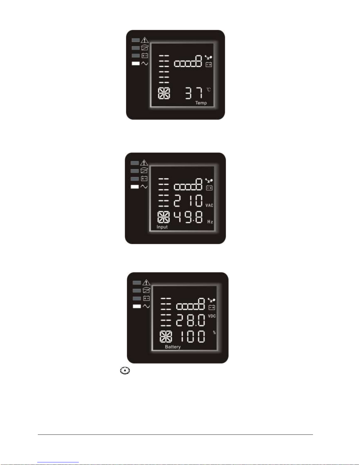
Temperature: Display the temperature of the inverter in the UPS. As the following graphics shows: the
temperature of the inverter is 37°C.
MISSION 1K●2K●3K
SINGLE PHASE
Rev. 02 –19 March 2015 18
Input: Display the voltage and frequency of the input. As the following graphics shows: the input voltage is
210V, input frequency is 49.8Hz.
Battery: Display the voltage and capacity of the battery (determined by type). As the following graphics shows:
the battery voltage is 28V, the capacity of battery is 100% (the capacity of battery is approximately
reckoned according to the battery voltage).
Press and hold the inquiring key for more than 2 seconds, LCD begins to display the items circularly and
orderly which transfer to another every 2 seconds. Press and hold the key for some time again, it will return to
output status.
4.5 Run mode
4.5.1 Bypass mode
LED indications on front panel in bypass mode are as following:

MISSION 1K●2K●3K
SINGLE PHASE
Rev. 02 –19 March 2015 19
Bypass yellow LED is on, the buzzer beeps once every 2 minutes. The warning red LED is on when beeping,
LCD displays are according to the exact load and battery capacity.
Turn to bypass mode under the following two conditions:
1. Turn off the UPS in line mode while start the bypass output.
2. Overload in line mode.
NOTE: When UPS is working in bypass mode, it has no back up function.
4.5.2 Line mode
LED indications on front panel in line mode are as following: The inverter green LED is on.
When input AC mains is in line with the working conditions, UPS will work in line mode.
4.5.3 Battery mode
LED indications on front panel in battery mode are as following: both the inverter green LED and battery yellow
LED are on, the buzzer beeps once every 4 seconds. The warning red LED is on when beeping.
When the mains power down or instable, UPS will turn to battery mode at once.
4.5.4 ECO mode
LED indications on front panel on ECO mode are as following: both the inverter green LED and bypass yellow
LED are on.
When the input mains meets the input range of the ECO mode and start the ECO function, the UPS will works
on ECO mode. If input AC mains exceeds the range of ECO several times in a row in a minute but stays in
inverter input range, UPS will work on AC inverting mode automatically.
4.5.5 Fault mode
LED indications on front panel in fault mode are as following: warning red LED is on

MISSION 1K●2K●3K
SINGLE PHASE
Rev. 02 –19 March 2015 20
Fault mode (LCD interface on which the fault code display)
When UPS has fault. The warning LED is on and the buzzer beeps. UPS will turn to fault mode. UPS cuts off
the output and LCD display fault codes. At the moment, you can press the mute key to make the buzzer stop
beeping temporarily to wait for maintenance. You can also press the OFF key to shut down the UPS when
confirm that there is no serious fault.
NOTE: As for corresponding information of the fault code, please refer to chapter 6.1
NOTICE:
★The following process must be performed if UPS is connected with generator:
★First turn on generator, after it runs stably connect output power of generator to UPS input terminal,
then turn on UPS. After UPS turned on, please connect load one-by-one.
★It is recommended that the generator capacity is as twice as UPS rated capacity
★You’d better not use the ECO mode when the quality of the input AC mains is not good.
5 MAINTENANCE
Only minimum maintenance is required for this series of UPS. The battery is sealed lead acid maintenance free.
It only needs to be kept charging to obtain the expected life. Whether it is started or not, the UPS would charge
batteries once it is connected to mains and provide protection for over-charging and deep discharging.
5.1 Battery maintenance
1. It is recommended that the batteries are manually charged or discharged once every three or four months if
UPS has not been used for a long time or the power is long-term uninterruptible. The battery will be fully
discharge to low-voltage protection shutdown. Then it needs to be fully charged once.
2. In high temperature area, batteries should be manually charged and discharged once every two months.
The process is the same as that said above.
3. Under normal circumstances of using, the battery working life is three to five years. If you find that the
battery do not act well such as obviously shortening of backup time, too much imbalance on battery voltage
so on, the battery should be replaced as soon as possible, which must be performed by qualified
personnel.
4. When replace battery, it is recommended to change battery all together instead of changing separately.
NOTICE:
★Before replacing batteries, first please turn off the UPS and break off the mains. Remove your metallic
adornment such as finger ring, watch and so on.
★When replace batteries, please use the screwdriver with insulating handle. Do not lay the tools or
metallic goods on the battery.
★Never reverse or short circuit between the battery anode and cathode.
6 TROUBLESHOOTING AND PERFORMANCE OF PRODUCT
The following messages are the information that users would find on UPS when it meets some problems. Users
can judge if the fault is caused by external factors and know how to deal with it by making full use of the
information.
1. Fault indicator on, indicates that the UPS has detected some faults.
2. Buzzer beeps, indicates that UPS need to be paid attention to, if beeps for a long time, it means that there
is something wrong with the machine.
3. If you need help, contact our service department, the following messages should be provided for analysis:
◆UPS MODEL NO. and SERIAL NO.
◆Date of fault happened
◆Detailed description of the problem (include indicator statements on panel)
This manual suits for next models
2
Table of contents
Other Elsist UPS manuals


Popular UPS manuals by other brands

CyberPower
CyberPower CP900EPFCLCD Technical specification

Huawei
Huawei UPS5000-E-600K-SC user manual

Bosch
Bosch Rexroth IndraControl VAU 01.1U Project planning manual

MGE UPS Systems
MGE UPS Systems EXL 1000 user guide

Huawei
Huawei PDU8000 Series Quick installation guide

Tescom
Tescom LEO LCD 650 user manual


Trust
Trust PW-4130M 1300VA MNGT UPS user manual

Uninterruptible Power Supplies
Uninterruptible Power Supplies PowerWAVE 9000 DPA Installation and operating guide

SKYPOINT
SKYPOINT Tiny quick start guide

SurgeX
SurgeX SU-1500-DC user manual

Panamax
Panamax MB1000 instructions

ABB
ABB Conceptpower DPA 500 user manual