Elsist UPserver 2.0 series User manual

UPServer2.0
ON-LINE DOUBLE CONVERSION
UPServer2.0
On Line Double Conversion 2KVA
Uninterruptible Power Supplies
USER MANUAL

UPServer2.0
ON-LINE DOUBLE CONVERSION
Table of Contents
1. INTRODUCTION ........................................................................................................................... 2
2. SAFETY WARNINGS.................................................................................................................... 3
3. INSTALLATION............................................................................................................................. 4
Inspecting the Equipment....................................................................................................................................4
Unpacking the Cabinet........................................................................................................................................4
Checking the accessories ...................................................................................................................................4
Rackmount Installation........................................................................................................................................5
Rackmount converted to Tower Installation ......................................................................................................11
4 OPERATION................................................................................................................................ 15
Control Cover Functions................................................................................................................................... 15
Table 1. Indicator Descriptions......................................................................................................................... 15
User Settings.................................................................................................................................................... 20
UPS Turn on and Turn off................................................................................................................................. 28
Start up operation ..................................................................................................................................... 28
Turn on the UPS in line mode................................................................................................................... 28
Turn on the UPS by DC without mains power.......................................................................................... 28
Turn off operation...................................................................................................................................... 29
Turn off the UPS in line mode................................................................................................................... 29
Turn off the UPS by DC without mains power.......................................................................................... 29
UPS self-test/mute test operation............................................................................................................. 29
Configuring Battery Settings ............................................................................................................................ 29
5. COMMUNICATION RS232, USB, OPTIONALS AND EPO....................................................... 30
Installing Communication Options and Control Terminals ............................................................................... 30
Communication Options................................................................................................................................... 30
RS-232 and USB Communication Ports................................................................................................... 30
Connectivity Cards.................................................................................................................................... 31
.................................................................................................................................................................. 32
6 UPS MAINTENANCE................................................................................................................................ 34
UPS and Battery Care...................................................................................................................................... 34
Storing the UPS and Batteries ......................................................................................................................... 34
Replacing Batteries .......................................................................................................................................... 34
Recycling the Used Battery or UPS................................................................................................................. 37
7. TECHNICAL SPECIFICATION................................................................................................... 37
8. TROUBLESHOOTING ................................................................................................................ 39

UPServer2.0
ON-LINE DOUBLE CONVERSION
Class B EMC Statements
(High Voltage Models up to 3000 VA)
FCC Part 15
NOTE This equipment has been tested and found to comply with the limits for a Class B digital device,
pursuant to part 15 of the FCC Rules. These limits are designed to provide reasonable protection
against harmful interference in a residential installation. This equipment generates, uses and can
radiate radio frequency energy and, if not installed and used in accordance with the instructions, may
cause harmful interference to radio communications. However, there is no guarantee that
interference will not occur in a particular installation. If this equipment does cause harmful
interference to radio or television reception, which can be determined by turning the equipment off
and on, the user is encouraged to try to correct the interference by one or more of the following
measures:
●Reorient or relocate the receiving antenna.
●Increase the separation between the equipment and the receiver.
●Connect the equipment into an outlet on a circuit different from that to which the receiver is
connected.
●Consult the dealer or an experienced radio/TV technician for help.
Special Symbols
The following are examples of symbols used on the UPS or accessories to alert you to important
information:
RISK OF ELECTRIC SHOCK - Observe the warning associated with the risk of electric shock
symbol.
CAUTION,need your attention
This symbol indicates that you should not discard the UPS or the UPS batteries in the trash. This product contains sealed, lead‐
acid batteries and must be disposed of properly. For more information, contact your local recycling/reuse or hazardous waste center.
This symbol indicates that you should not discard waste electrical or electronic equipment (WEEE) in
the trash. For proper disposal, contact your local recycling/reuse or hazardous waste center.
UPServer2.0
ON-LINE DOUBLE CONVERSION
1. Introduction
This UPS protects your sensitive electronic equipment from most common power problems,
including power failures, power sags, power surges, brownouts, line noise, high voltage spikes,
frequency variations, switching transients, and harmonic distortion.
Power outages might occur unexpectedly and power quality can be erratic. These power problems
have potential to corrupt critical data, destroy unsaved work sessions, and damage hardware —
causing hours of lost productivity and expensive repairs.
With the UPS, you can safely eliminate the effects of power disturbances and guard the integrity
of your equipment. Providing outstanding performance and reliability, the UPS's unique benefits
include:
True online double-conversion technology with high power density, utility
frequency independence, and generator compatibility. Output power factor
up to 0.9.
Three segment charging mode to increase battery service life, optimize
recharge time.
Selectable High Efficiency mode of operation.
Cold start function to startup the UPS without utility.
Standard communication options: one RS-232 communication port, one
USB communication port, and relay output contacts or SNMP card.
Power Shedding function may turn off uncritical load in battery backup to
make longer backup time for critical load.
Extended runtime with up to four Extended Battery Modules (EBPs) per UPS.
Emergency shutdown control through the Remote Emergency Power-off
(EPO) port.
The content displayed on the interface is rich. The capacity of the loads and
the battery can be seen directly and the FLASH pictures and fan rotating icon
can be displayed while charging. Enhance, it is easy to know its operation
status. When UPS fails, it can show the fault code; therefore, the UPS can
be repaired as soon as possible by inquiring fault code table.
NOTICE: In the manual, RT is short for Rack-Tower conversion
Rack/Tower convertible LCD design. No matter what angle required, only
pressing the key slightly to reach your perspective needs.
For RT model, it is equipped with hot swappable battery feature needed for
19”rack solution.
RT models in a space-optimizing 2U size fits any standard 19”rack.
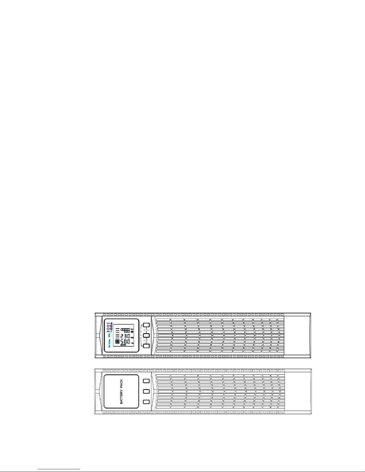
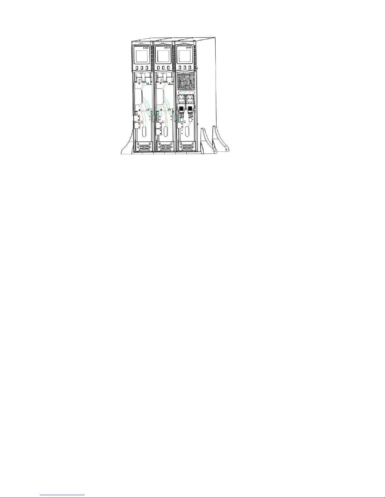
Fig.1
Fig.2
Figure1 –UPS Front View
Figura2 –Battery Expansion “EBP”Front View

UPServer2.0
ON-LINE DOUBLE CONVERSION
2. SAFETY WARNINGS
IMPORTANT SAFETY INSTRUCTIONS
SAVE THESE INSTRUCTIONS
This manual contains important instructions that you should follow during
installation and maintenance of the UPS and batteries. Please read all
instructions before operating the equipment and save this manual for future
reference.
DANGER
The UPS contains LETHAL VOLTAGES. All repairs and service should be
performed by AUTHORIZED SERVICE PERSONNEL ONLY. There are NO USER
SERVICEABLE PARTS inside the UPS.
WARNING
The UPS contains its own energy source (batteries). The UPS output may
carry live voltage even when the UPS is not connected to an AC supply.
To reduce the risk of fire or electric shock, install the UPS in a temperature
and humidity controlled, indoor environment, free of conductive
contaminants. Ambient temperature must not exceed 40°C (104°F). Do not
operate near water or excessive humidity (90% maximum).
To reduce the risk of fire, connect only to a circuit provided with branch
circuit overcurrent protection in accordance with the National Electrical
Code (NEC), ANSI/NFPA 70.
Output overcurrent protection and disconnect switch must be provided by
others.
To comply with international standards and wiring regulations, the sum of
the leakage current of the UPS and the total equipment connected to the
output of the UPS must not have an earth leakage current greater than 3.5
milliamperes.
If installing optional rackmount EBP(s), install the EBP(s) directly below the
UPS so that all wiring between the cabinets is installed behind the front
covers and is inaccessible to users. The maximum number of EBP(s) per UPS
is four.
If the UPS requires any type of transportation, verify that the UPS is
unplugged and turned off and then disconnect the UPS internal battery
connector.
CAUTION
Batteries can present a risk of electrical shock or burn from high short-circuit
current. Observe proper precautions. Servicing should be performed by
qualified service personnel knowledgeable of batteries and required
precautions. Keep unauthorized personnel away from batteries.
Proper disposal of batteries is required. Refer to your local codes for disposal
requirements.
Never dispose of batteries in a fire. Batteries may explode when exposed to flame.

UPServer2.0
ON-LINE DOUBLE CONVERSION
3. INSTALLATION
This section explains:
Equipment inspection
Unpacking the cabinet
Checking the accessory kit
Cabinet installation
Wiring installation
Initial startup
Inspecting the Equipment
If any equipment received has been damaged during shipment, keep the
shipping cartons and packing materials for the carrier or place of purchase and
file a claim for shipping damage. If you discover damage after acceptance, file a
claim for concealed damage.
To file a claim for shipping damage or concealed damage: 1) File with the carrier
within 15 days of receipt of the equipment; 2) Send a copy of the damage claim
within 15 days to your service representative.
NOTE Check the battery recharge date on the shipping carton label. If the date has expired and the
batteries were never recharged, do not use the UPS. Contact your service representative.
Unpacking the Cabinet
CAUTION
Unpacking the cabinet in a low-temperature environment may cause
condensation to occur in and on the cabinet. Do not install the cabinet until
the inside and outside of the cabinet are absolutely dry (hazard of electric
shock).
The cabinet is heavy (see page 65). Be careful to unpack and move the
cabinet.
Carefully to move and open the carton. Keep the components packaged until
ready to install.
To unpack the cabinet and accessories:
1. Open the outer carton and remove the accessories packaged with the cabinet.
2. Carefully lift the cabinet out of the outer carton.
3. Discard or recycle the packaging in a responsible manner, or store it for future
use.
Place the cabinet in a protected area that has adequate airflow and is free of
humidity, flammable gas, and corrosion.
Checking the accessories
It includes:
UPS user's guide
Software Suite CD
USB cable

UPServer2.0
ON-LINE DOUBLE CONVERSION
Power cord (Input and output)
RS232 cable
If you ordered an optional Extended Battery Module (EBP), verify that the
following additional item is included with the EBP:
●EBP user's guide
NOTE Discard the EBP user's guide if you are installing the EBP with a new UPS at
the same time. Use the UPS user's guide to install both the UPS and the EBP.
Rackmount Installation
The Rackmount cabinet comes with all of the hardware required for installation in a
standard EIA or JIS seismic Rackmount configuration with square and round mounting
holes. The rail assemblies adjust to mount in 19”racks with a distance from front to rear
around 70~76 cm (27 to 30 inches) deep.
Checking the Rail Kit Accessories(Options)
Verify that the following rail kit items are included for each cabinet:
Left rail assembly:
- Left rail
- Rear rail
- (3) M5_8 pan-head screws
Right rail assembly:
- Right rail
- Rear rail
-(3) M5_8 pan-head screws
Rail hardware kit:
- (8) M5 butterfly nuts
- (2) rear stop brackets
- (8) M5 umbrella nuts
Mounting bracket kit:
- (2) mounting brackets
- (8) M4_8 flat-head screws
Tools Required
To assemble the components, the following tools may be needed:
cross-shaped screwdriver
5 and 6 mm wrench or socket
Rackmount Setup CAUTION
The cabinet is heavy. Removing the cabinet from its carton requires a
minimum of two people.
If installing optional EBP(S), make sure to install the EBP(S) directly below the
UPS so that all wiring between the cabinets is installed behind the front
covers and inaccessible to users.
NOTE
Mounting rails are required for each individual cabinet
To install the rail kit:
UPServer2.0
ON-LINE DOUBLE CONVERSION
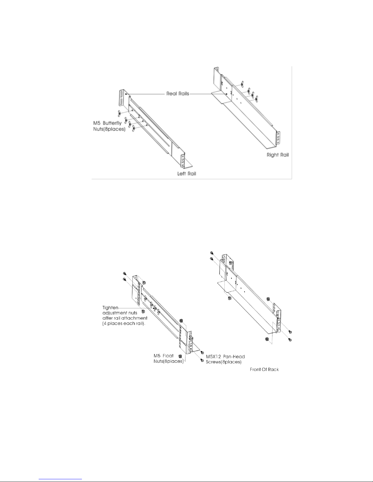
1. Assemble the left and right rails to the rear rails as shown in Figure4.Do not
tighten the screws.
Adjust each rail size for the depth of your rack.
Figure3 Securing the Rails
1. Select the proper size in the rack for positioning the UPS (see Figure 5). The rail
occupies four positions on the front and rear of the rack.
2. Tighten four M5 Umbrella Nuts in the side of rail assembly (see Figure 4).
3. Fix one rail assembly to the front of the rack with one M5×12 pan-head screw
and one M5 cage nut. Using two M5 cage nuts and two M5×12 pan-head screws,
to fix the rail assembly to the rear of the rack.
Figure4 Fixing the Rails
4. Repeat Steps 3 and 4 for the other rail assembly.
5. Tighten the four butterfly nuts in the middle of each rail assembly.
6. If installing optional cabinets, repeat Step 1 through Step 6 for each rail kit.
UPServer2.0
ON-LINE DOUBLE CONVERSION
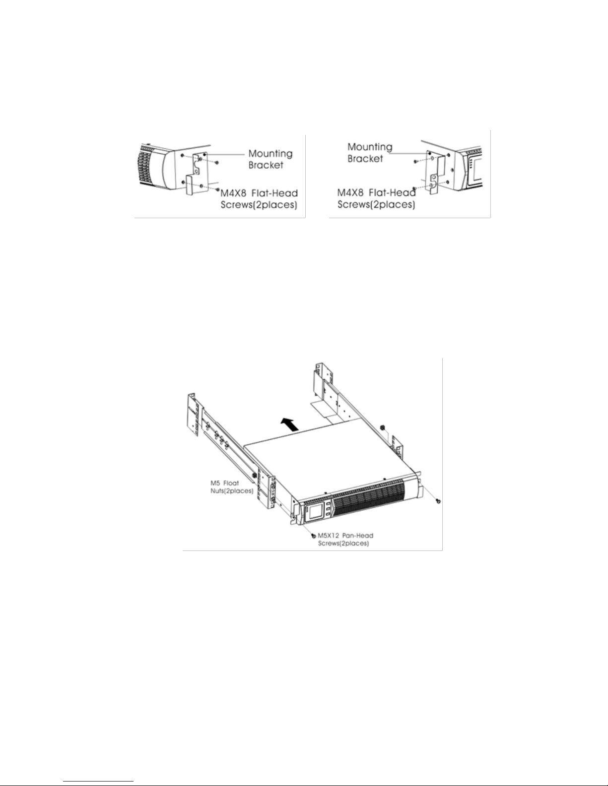
7. Place the UPS on a flat, stable surface with the front of the cabinet facing to
you.
8. Align the mounting brackets with the screw holes on each side of the UPS
and fix with the supplied M4×8 flat-head screws(see Figure 6)
Figure5 Installing the Mounting Brackets
9. If installing optional cabinets, repeat Step 8 and 9 for each cabinet.
10. Slide the UPS and any other optional cabinets into the rack.
11. Secure the front of the UPS to the rack using one M5×12 pan-head screws and
one M5 cage nuts on each side(see Figure 7).Install the bottom screw on each
side through the bottom hole of mounting bracket and the bottom hole of the
rail.
Repeat for any optional cabinets.
Figure6 Securing the Front of the Cabinet
12. Continue to the following section, “Rackmount Wiring Installation.
UPServer2.0
ON-LINE DOUBLE CONVERSION
Rackmount Wiring Installation
This section explains:
Installing the UPS, including connecting the UPS internal batteries
Connecting any Optional EBP(S)
Installing the UPS
NOTE
Do not make unauthorized changes to the ups; otherwise, damage may
occur to your equipment and void your warranty.
NOTE
Do not connect the ups power cord to utility until after installation is
completed.
To install the UPS:
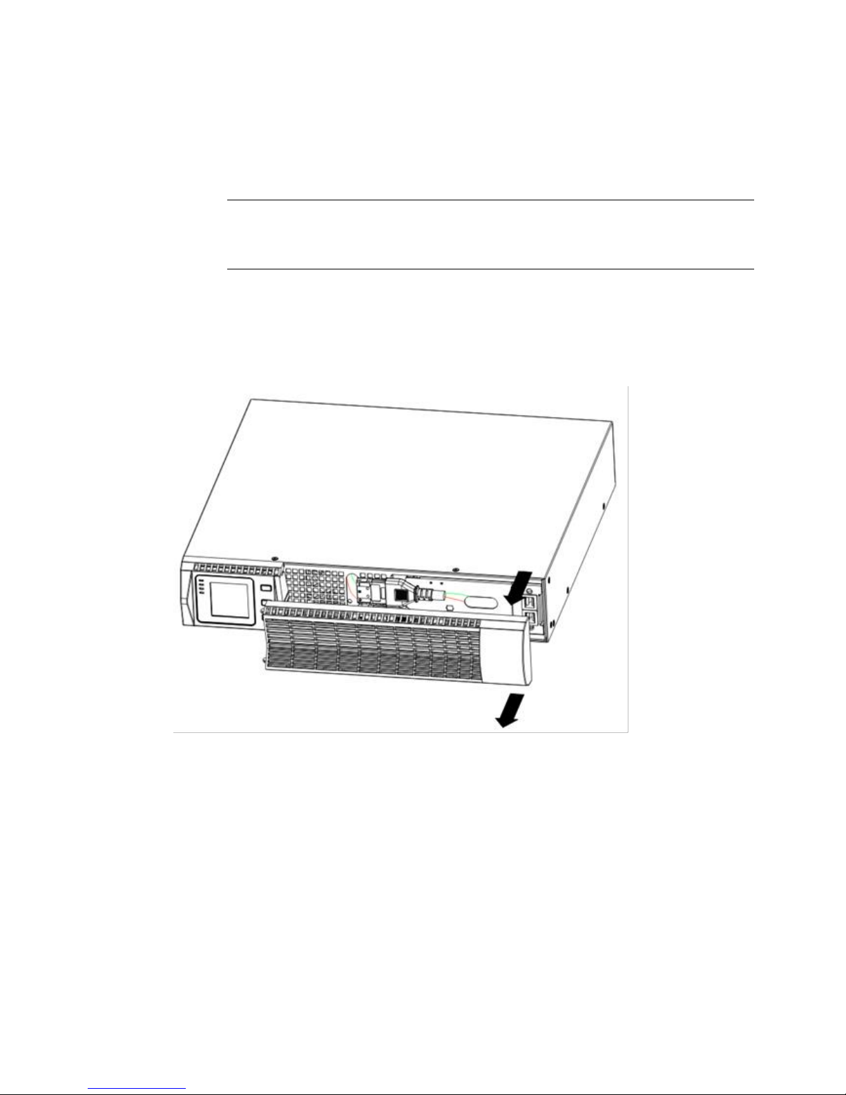
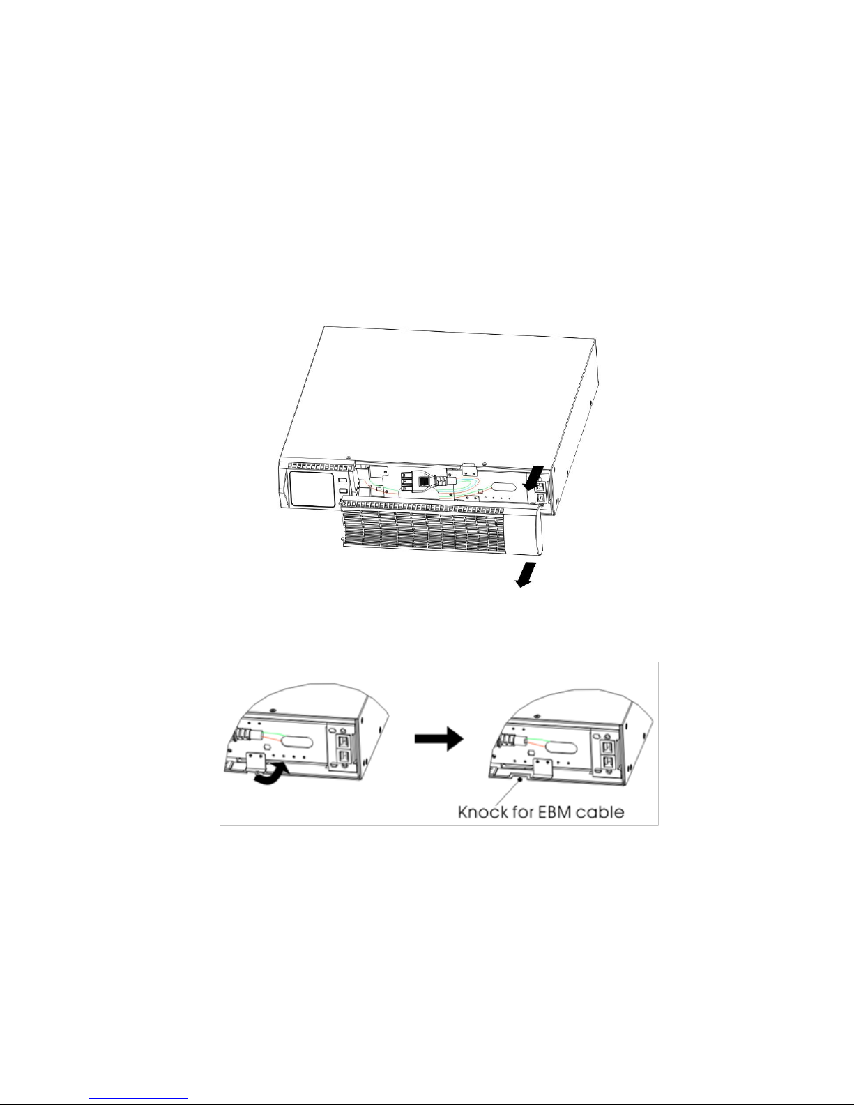
1. Remove the front cover of each UPS
Hold the cover part without LCD on the right side and extract it(see Fig.7)
Figure7 Extract UPS front cover
2. Connect the internal battery connector (see Figure8)
Connect red to red, Press the connector tightly together to ensure a proper
connection.
UPServer2.0
ON-LINE DOUBLE CONVERSION
CAUTION
A small amount of arcing may occur when connecting the internal batteries. This is
normal and will not harm personnel. Connect the cables quickly and firmly
.
Figure8 Connecting the UPS Internal Batteries
3. If you are installing EBPS, see the following section, “Connecting the EBP(s),”before
continuing with the UPS installation.
4. Replace the UPS front cover.
To replace the cover, verify the EBP cable is routed through the knockout on the bottom of
the cover if EBPS are installed.
Put the front cover hooks of side with display to the cover port, put another side to the
other two ports, then press it until the cover and the chassis are combined tightly.
Figura 9
5. If you are installing power management software, connect your computer to one of the
communication ports or optional connectivity card. For the communication ports, use an
appropriate cable.
6. If your rack has conductors for grounding or bonding of ungrounded metal parts,
UPServer2.0
ON-LINE DOUBLE CONVERSION
connect the ground cable (not supplied) to the ground bonding screw. See“Rear Covers”
for the location of the ground bonding screw for each model.
7. If an emergency power-off (disconnect) switch is required by local codes, see “Remote
Emergency Power-off”(REPO) to install the REPO switch before powering on
the UPS.
8. Continue to “UPS Initial Startup”.
Connecting the EBP(s)
To install the optional EBP(s) for a UPS:
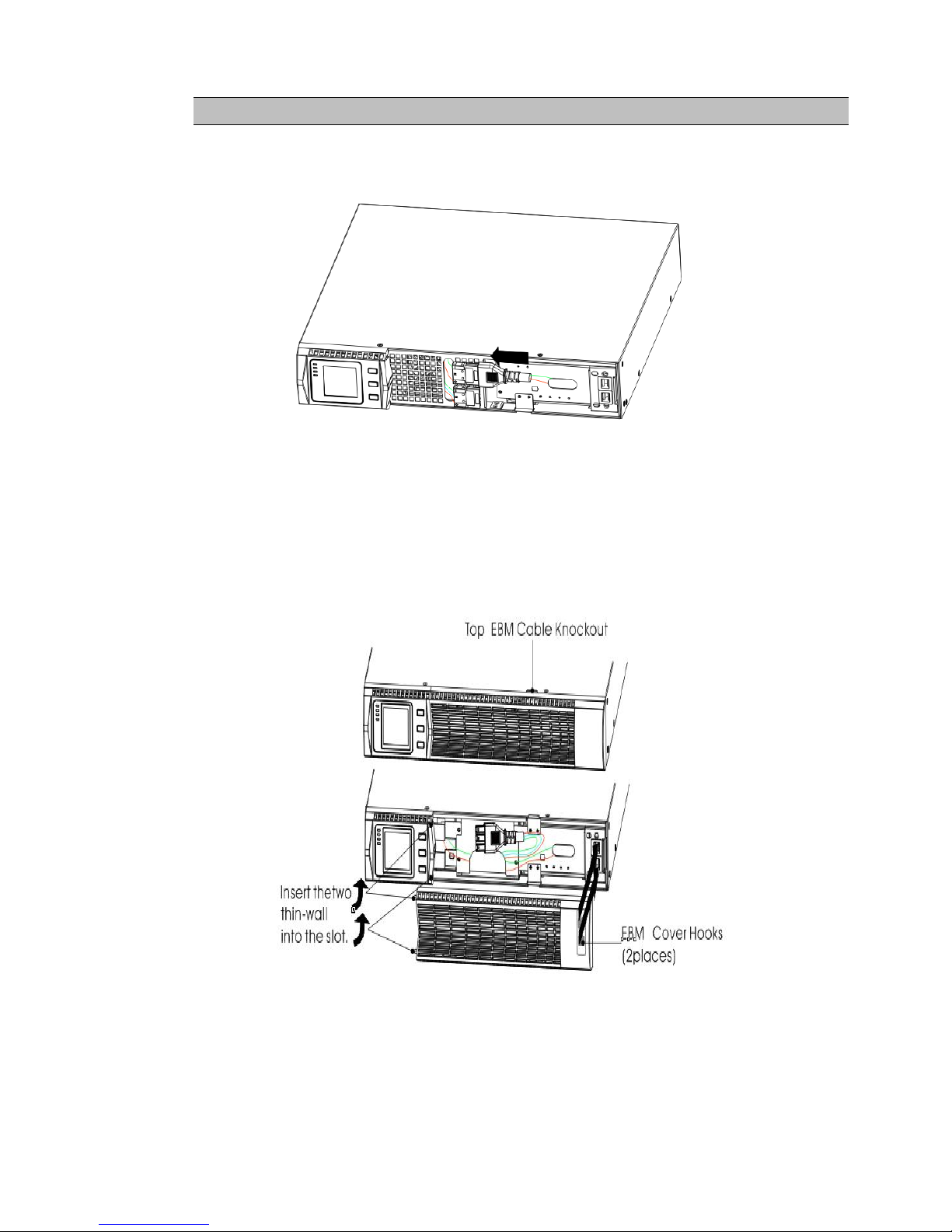
1. Remove the front cover of each EBP and UPS (see Figure 11).
It is the same with the installation of the front cover. (Refer” To install the UPS “)
Figure10 Removing the EBP Front Cover
2. On the bottom of the UPS front cover, remove the EBP cable knockout (see Figure 12).
Figure11 Removing the UPS Cable Knockout
3. For the bottom (or only) EBP, remove the EBP cable knockout on the top of the
EBP front cover. See Figure 13 for the location of the top EBP cable knockout.
4. If you are installing more than one EBP, for each additional EBP remove the EBP
cable knockout on the top and bottom of the EBP front cover. See Figure 13 for
the location of the EBP cable knockouts.
UPServer2.0
ON-LINE DOUBLE CONVERSION
CAUTION
A small amount of arcing may occur when connecting an EBP to the UPS. This is normal
and will not harm personnel. Insert the EBP cable into the UPS battery connector quickly
and firmly.
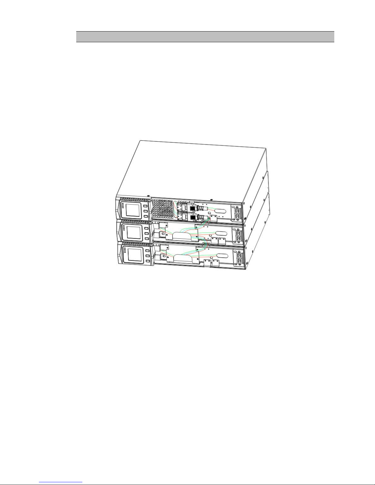
5. Plug the EBP cable(s) into the battery connector(s) as shown in Figure 13. Up to four
EBPS may be connected to the UPS. Connect black to black,. Press the connector tightly
together to ensure a proper connection.
To connect a second EBP, unclip the EBP connector on the first EBP and pull gently to
extend the wiring to the EBP connector on the second EBP. Repeat for any additional
EBPS.
6. Verify that the EBP connections are tight and the adequate bend radius and strain relief
exist for each cable.
Figure12 Typical EBP Installation
7. Replace the EBP front cover.
To replace the cover, verify that the EBP cables are routed through the EBP cover knockouts, cover
connects with the cover hook near the left side of the EBP cabinet. Repeat for each additional EBP.
It is the same with the installation of the front cover. (Refer”to UPS installation”)
8. Verify that all wires connected between the UPS and EBP(s) are installed behind the front covers
and not accessible to users.
9. Return to Step 4 to continue the UPS installation.
Rackmount converted to Tower Installation
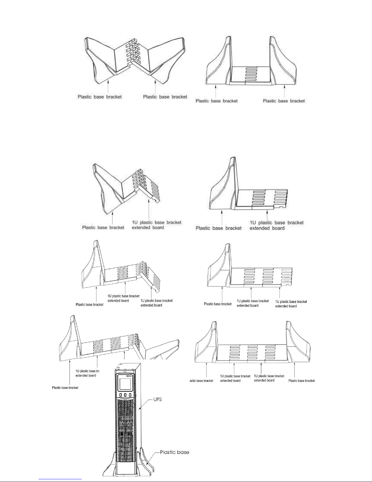
1.Rackmount converted to Tower plastic base installation
①two plastic base brackets ②flatten it after intercrossing
intercross as following Figure
UPServer2.0
ON-LINE DOUBLE CONVERSION
Figure 13 plastic base installation
③If an EBP is needed to be placed in the middle, the assembly of plastic base is similar ,
The difference is that two 1U plastic base extended boards are added in the middle.(as the
following shows)
(A)(B)
(C)(D)
(E) (F)
Figure 14 increase EBP plastic base installation
2. The installation between UPS and EBPS can be
referred to Fig.15
UPServer2.0
ON-LINE DOUBLE CONVERSION
Figure15 The installation for UPS and battery box
1.Install the base, then place the RT UPS on the base one by one as Fig.16 shows.
2. The cover installation and cable connection of the UPS and EBPS are the same as RT. (To install
the optional EBP(s) for a UPS)

UPServer2.0
ON-LINE DOUBLE CONVERSION
UPS initial startup
To start up the UPS:
NOTE Verify that the total equipment ratings do not exceed the UPS capacity to prevent
an
Overload alarm
1. If optional EBPs are installed, verify that the EBPs are connected to the UPS.
2. Plug the equipment to be protected into the UPS, but do not turn on the
protected equipment.
3. Make any necessary provisions for cord retention and strain relief.
4. Plug the detachable UPS power cord into the input connector on the UPS
rear cover.
5. Plug the UPS power cord into a power outlet. The UPS front cover display
illuminates.
6. The UPS will do self-test when power on. After that, the charger will
charge the battery. If the output displayed on LCD is “0”, there is no
output. If you need the UPS output the utility without starting the UPS when
plug into the utility,you need to set bPS option to “ON”on the setting
mode,refer to Page 38.
7. Press the combination start up buttons on the UPS front cover for at least
half a second. The UPS will start up and the LED will turn on and off
sequentially.
8. Check the UPS front cover display for active alarms or notices. Resolve any
active alarms before continuing. See Troubleshooting”. If the indicator
is on, do not proceed until all alarms are clear.Check the UPS status from
the front cover to view the active alarms. Correct the alarms and restart if
necessary.
10. Verify that the indicator illuminates solid, indicating that the UPS is
operating normally and any loads are powered.
11. If optional EBPs are installed, see “Configuring Battery settings”on page
41 to set the number of installed EBPs.
12. To change any other factory-set defaults, see “User settings”
NOTE: At initial startup, the UPS sets system frequency according to input line
frequency (input frequency auto-sensing is enabled by default).
NOTE: At initial startup,please set the output voltage needed before start up the
UPS,After the subsequent startup,the UPS will output the setting voltage.
13.If you installed an optional EPO, test the EPO function: Activate the external
EPO switch. Verify the status change on the UPS display. Deactivate the
external EPO switch and restart the UPS.
NOTE:The internal batteries charge to 80% capacity in less than 5 hours. However,
we recommend that the batteries should be charged for 48 hours after
installation or long-term storage. If optional EBPs are installed, see the
recharge times listed in Table 21.

UPServer2.0
ON-LINE DOUBLE CONVERSION
4 OPERATION
This chapter contains information on how to use the UPS, including front cover operation,
operating modes, UPS startup and shutdown, transferring the UPS between modes, and
configuring bypass settings, load segments, and battery settings.
Control Cover Functions
The UPS has a three-button segmental LCD with backlight. It provides useful information about
the UPS itself, load status, measurements, and settings.
Figure16. Control Cover
Table 1. Indicator Descriptions
Indicator
Description
Red
On The UPS has an active alarm or fault.
Yellow
On The UPS is in Bypass mode.
The UPS is operating normally on bypass
during High Efficiency operation.
Yellow
On The UPS is in Battery mode.
Green
On The UPS is operating normally.
NOTE When power on or startup , these indicators will turn on and off
sequentially.
NOTE On different operation modes , these indicators will indicate differently.
Refer to Table 7.
UPServer2.0
ON-LINE DOUBLE CONVERSION
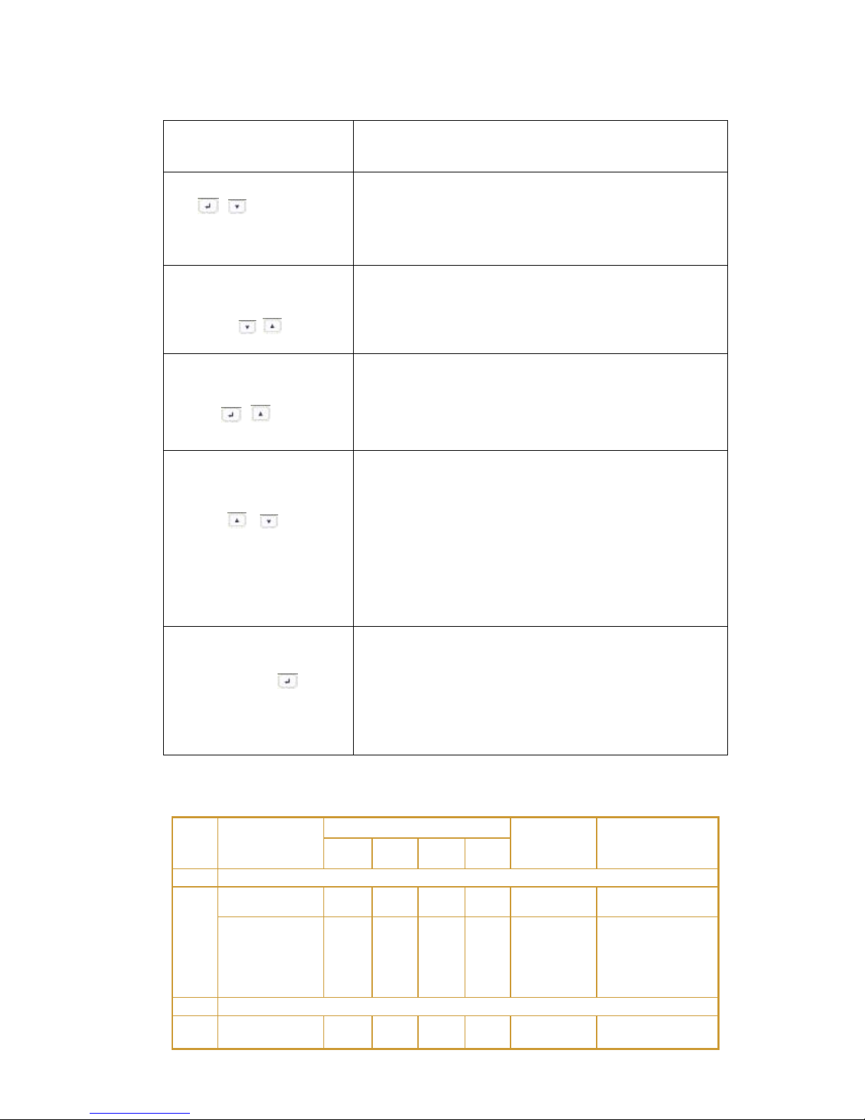
Table 2 . Button function
Button
Function description
Start up combination
(+)
TOWER Press and hold this key for more than half a
second to turn on the UPS.
RT Press and hold this key for more than half a
second to turn on the UPS or to turn off the UPS.
Shutdown/Rotating
combination
(+)
TOWER Press and hold this key for more than half a
second to turn off the UPS.
RT Press and hold this key for more than 2 seconds
to circumrotate the LCD .
Battery test/Mute
combination
(+)
Press and hold the key for more than 1 second in Line
mode or economic(ECO) mode: UPS runs self-test
function.
Press and hold the key for more than 1 second in
battery mode: UPS runs mute function.
Scroll or
Non-function setting mode:
Press and hold the key for more than half a second
(less than 2 seconds): Indicate the items of the LCD
item section orderly.
Press and hold this key for more than 2 seconds:
Circularly and orderly display the items every 2
seconds, when press and hold the key for some time
again, it will turn to output status.
Function setting mode:
Press and hold the key for more than half a second
(less than 2 seconds): Select the set option.
Setting entry
Non-function setting mode:
Press and hold the key for more than 2 seconds:
Function setting interface.
Function setting mode:
Press and hold the key for more than half a second
(less than 2 seconds): Affirm the set option.
Press and hold the key for more than 2 seconds, exit
from this function setting interface.
Table 3. The corresponding working status of indications
NO
Working
status
Indication
Warning
Remarks
Nor
Bat
Bps
Fau
1
Line mode
Normal
voltage
●
None
High/low
voltage
protection,
turn to
battery mode
●
●
★
Once
every four
seconds
2
Battery mode
Normal
voltage
●
●
★
Once
every four

UPServer2.0
ON-LINE DOUBLE CONVERSION
seconds
Battery
Voltage
abnormal
warning
●
★
★
Once per
second
3
Bypass mode
Main AC
Normal
voltage in
bypass mode
●
★
Once
every two
minutes
Eliminate after
starting the UPS
Main AC high
voltage
warning in
bypass mode
★
Once
every four
seconds
Main AC low
voltage
warning in
bypass mode
★
Once
every four
seconds
4
Battery disconnect warning
Bypass mode
●
★
Once
every four
seconds
Affirm if the
battery switch is
closed
Inverting
mode inverting
mode
●
★
Once
every four
seconds
Affirm if the
battery switch is
closed
Power up or
start
Six times
Affirm if the
battery is
connected well
5
Output overload protection
Overload
warning in
line mode,
●
★
Twice per
second
Remove the
uncritical loads
Overload in
line mode,
protection
●
●
Long
beeps
Remove the
uncritical loads
Overload
warning in
battery mode
●
●
★
Twice per
second
Remove the
uncritical loads
Overload in
battery
mode,
protection
●
●
●
Long
beeps
Remove the
uncritical loads
6
Overload
warning in
bypass mode
●
★
Once
every 2
seconds
Remove the
uncritical loads
7
Fan fault (fan
icon flashing)
▲
▲
▲
★
Once
every 2
seconds
Check if the fan
is blocked by
object.
8
Fault mode
●
Long
beeps
If display fault
code and
icon lights,
contact for
maintenance
when you
can’t deal with
it by yourself.
● _indicator lights for a long time

UPServer2.0
ON-LINE DOUBLE CONVERSION
★ _indicator flashes
▲ _the status of indicator depends on other conditions
Display Functions
As the default or after 5 minutes of inactivity, the LCD displays the
output parameters.
The backlit LCD automatically dims after 5 minutes of inactivity. Press
any button to restore the screen.
LCD display comprises numerical value section, capacity graphics section, fan-status graphics
section and charger-status graphics section , refer to Table 4 for detail.
Table 4. LCD display section
Section
Description
Graphic
Numerical
value
section
Display the corresponding numerical
value of inquiring items(output, load,
temperature, input, battery), for
example, as the graphics shows above,
the output voltage is 230v, the output
frequency is 50Hz.
Capacity
graphics
section
Display the capacity of the battery and
load. Every pane represents 20 %
capacity. As graphics shown above,
the capacity of the battery is 80%
-100%( 5 panes), the load reaches
40 %-60 %(3 panes). When UPS is
overloaded, the icon will flash, when
battery is weak or disconnected, the
icon will also flash.
Fan-status
graphics
section
Display if the fan works normally.
When the fan works normally, it will
show the dynamic fan blades rotating;
when the fan works abnormally, the
icon will keep on flashing with the
warning .
Table of contents
Other Elsist UPS manuals


