elsner elektronik WL305 User manual

Technical specifications and installation instructions
EN
Elsner Elektronik GmbH Control and Automation Engineering
Herdweg 7
Germany Fax +49 (0) 70 56 / 93 97-20 www.elsner-elektronik.de
WL305
Ventilation Unit
for air extraction and recirculation
Interior view

2 Description
Ventilation Unit WL305 • Date of issue: 25.05.2011 • Technical changes reserved. Errors reserved.
1. Description
The Ventilation Unit WL305 is installed in the roof ridge area of conservatories in-
stead of the normal glazing. The WL305 can be operated in air extraction and recircu-
lation modes. The recirculation mode may be used for heat gain and reduction of water
condensation thanks to an integrated temperature sensor in the ventilation unit.
The WL305 communicates wireless with the control systems WS1 Color, WS1000 Co-
lor and KNX WS1000 Color. The Ventilation Unit WL305 may be operated directly
with the Remo 8 Remote Control.
Functions:
•Air extraction mode. Please pay attention to an adequate opening for supply
air of approx. 6120 mm² per WL610 (e. g. one Supply Air Unit WFL or equal
window opening)
•Recirculation mode for heat gain: Warm air from the ridge is spread in the
whole room
•Recirculation mode for reduction of condensation water: The controls
register critical conditions of temperature and dew point with the help of a
special calculation method and start the ventilation unit in the mayor of cases
even bevor humidity precipitates
•Wireless control without additional device, only the power supply has to be
connected
• Quiet lateral blower
•Highlyheat insulating housing consists of integral skin foam
•Extremelytight closing flap (spur gear, worm drive) with self-locking drive
and load limit switch
•Theinstallation panel is powder-coated on both sides and has an extremely
high compressive strength
• May be installed together with self-cleaning panes bacause of the silicon-free
manufacture
• The power and radio electronics are built inside, yet not in the way of the air
current. Full maintenance from inside is possible
• Manual operation with Remo 8 Remote Control possible (available separately)
1.0.1. Scope of delivery
• Installation panel with ventilation unit and 10 m connection lead for voltage
supply
1.1. Technical specifications
Mains voltage 230 VAC, 50 Hz
Length connectiong lead
power supply
10 m
Power consumption Maximum: approx. 40 VA
Standby: approx. 2 VA

3 Description
Ventilation Unit WL305 • Date of issue: 25.05.2011 • Technical changes reserved. Errors reserved.
The following standards have been considered for the evaluation of the product in
terms of electro magnetic compatibility:
• EN 610000-3-2:2006 + A1:2009 + A2:2009
• EN 610000-3-3:2008
• EN 301 489-1 V1.8.1
• EN 300 220-2 V2.1.2
The product has been tested for the above mentioned standards by an accredited EMV
laboratory.
1.1.1. Dimensions
Radio frequency 868,2 MHz
Air volume blower approx. 305 m3/h according to DIN 24 163
Net air rating Extracted air max. approx. 226 m³/h,
Recirculated air max. approx. 271 m³/h
(Refer to Elsner Elektronik for the precise criteria)
Required opening
for supply air
6 120 mm² per WL305 (e. g. one Supply Air Unit WFL
or equal window opening)
Sound pressure at 2 m distance:
max. approx. 58.2 dB(A) at full load
U-value insulating panel: 1,03 W/m²K.
ventilator total: approx. 1,8 W/m²K, calculated (presup-
position: area ventilator = area panel)
Volumetric weight of insu-
lating panel
60 kg
Compressive strength of
panel
350 kPa
Minimum roof inclination 4°
For roof inclinations between 4° and 15°, we recom-
mend ordering the ventilation unit as version for small
angles of inclination. In this case the device comes
with an additional rain water barrier. Please notice that
the air outlet port is reduced slightly by the barrier and
thus the air volume is reduced.
Installation height
of ventilator
Outer: approx. 81 mm
Inner: approx. 81 mm
Width of ventilator approx. 501 mm
Depth of ventilator approx. 298 mm
Standard panel approx. 1050 mm x 700 mm (W x D), thickness approx.
30 mm.
The standard panel can be trimmed on three sides (see
Fig. 1, page 4)

4 Description
Ventilation Unit WL305 • Date of issue: 25.05.2011 • Technical changes reserved. Errors reserved.
For an additional charge, the panel can be delivered already in the dimensions you
need. A different panel thickness is also possible upon request (panel thickness 24-40
mm).
Minimal dimensions for panel:
(shortening or special panel)
1.1.2. Colours
Standard colours for ventilator and panel (included in price):
• RAL 9016 Traffic White
• RAL 9006 White Aluminium
• RAL 9007 Grey Aluminium
Minimum width approx. 640 mm
(Width of ventilator approx. 501 mm
plus 50 mm on both sides
plus the size required on both sides for installation)
Minimum depth
for shortening
approx. 520 mm
(Depth of ventilator approx. 298 mm
plus 100 mm at the top (can not be trimmed)
plus 100 mm at the bottom
plus the size required at the bottom for installation)
Minimum depth
special panel
approx. 490 mm
(Depth of ventilator approx. 298 mm
plus 50 mm at the top
plus 100 mm at the bottom
plus the size required at the top/bottom for installa-
tion)
Fig. 1
Trimming of standard panel
Voltage supply
5 Installation and commissioning
Ventilation Unit WL305 • Date of issue: 25.05.2011 • Technical changes reserved. Errors reserved.
All other RAL colours are also available at an additional charge (also two-coloured in-
side – ouside).
Note: The delivered colour tones are similar to the RAL colours specified. Deviations
due to technical reasons are possible. Due to the different nature of the surface of the
panel and ventilator housing, slightly different degrees of lustre can occur.
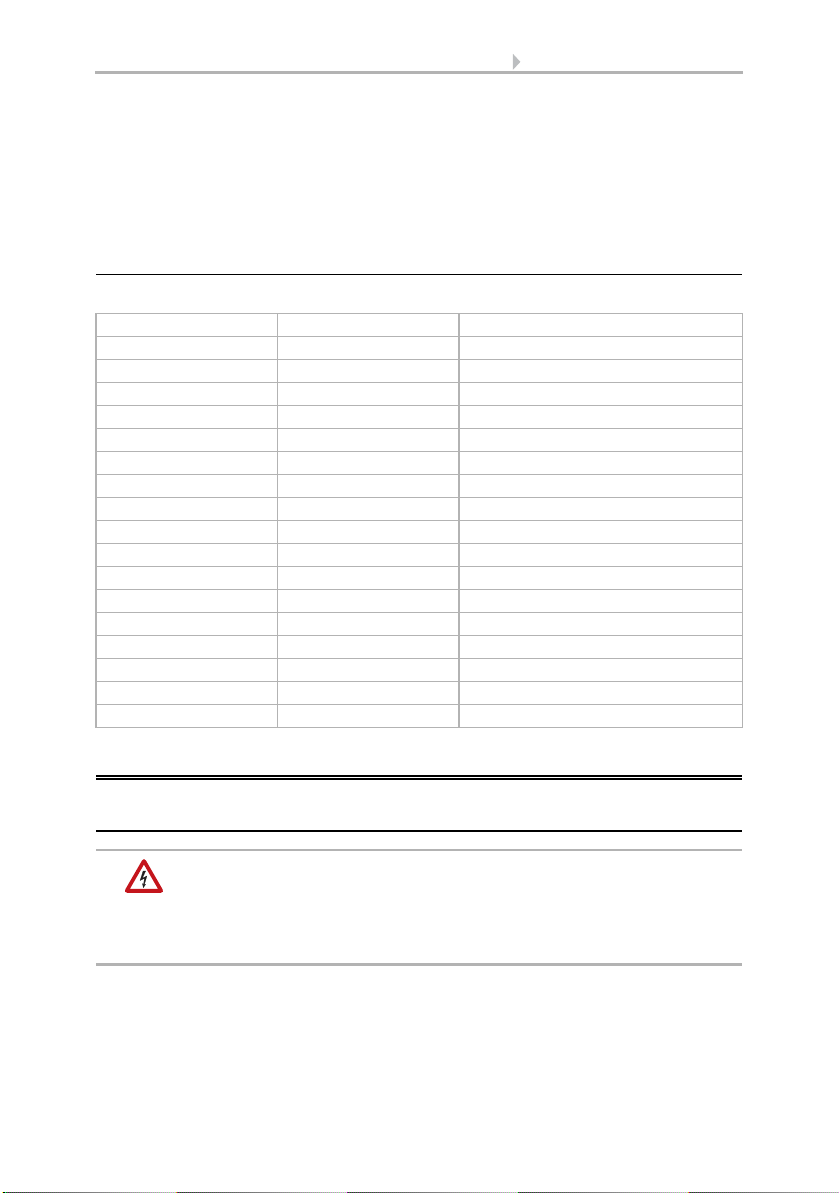
1.1.3. Ventilation levels
Order of the ventilation levels:
2. Installation and commissioning
2.1. Notes on installation
Warning, mains voltage!
National legal regulations are to be observed.
Installation, inspection, commissioning and troubleshooting of the
device must only be carried out by a competent electrician.
Disconnect all lines to be assembled, and take safety precautions against accidental
switch-on.
Level Flap Blower
Extraction 8 opened runs, highest speed
Extraction 7 opened runs
Extraction 6 opened runs
Extraction 5 opened runs
Extraction 4 opened runs
Extraction 3 opened runs
Extraction 2 opened runs, lowest speed
Extraction 1 opened stopped
Off closed stopped
Recirculation 1 closed runs, lowest speed
Recirculation 2 closed runs
Recirculation 3 closed runs
Recirculation 4 closed runs
Recirculation 5 closed runs
Recirculation 6 closed runs
Recirculation 7 closed runs
Recirculation 8 closed runs, highest speed

6 Installation and commissioning
Ventilation Unit WL305 • Date of issue: 25.05.2011 • Technical changes reserved. Errors reserved.
The device is exclusively intended for appropriate use. With each inappropriate change
or non-observance of the instructions for use, any warranty or guarantee claim will be
void.
After unpacking the device, check immediately for any mechanical damages. In case of
transport damage, this must immediately notified to the supplier.
If damaged, the device must not be put into operation.
If an operation without risk may supposedly not be guaranteed, the device must be put
out of operation and be secured against accidental operation.
The device must only be operated as stationary system, i.e. only in a fitted state and
after completion of all installation and start-up works, and only in the environment in-
tended for this purpose.
Elsner Elektronik does not assume any liability for changes in standards after publica-
tion of this instruction manual.
2.2. Notes on wireless equipment
When planning facilities with devices that communicate via radio, adequate radio re-
ception must be guaranteed. The range of wireless control will be limited by legal reg-
ulation and structural circumstances. Avoid sources of interference and obstacles be-
tween receiver and transmitter, that could disturb the wireless communication. Those
would be for example:
• Walls and ceilings (especially concrete).
• Metal surfaces next to the wireless participants (e. g. aluminium construction
of a conservatory).
• Other wireless devices and powerful local transmitters (e.g. wireless
headphones), which transmit on the same frequency (868,2 MHz). Please
maintain a minimum distance of 30 cm between wireless transmitters for that
reason.
2.3. Notes on mounting
The ventilator panel with the ventilator must be mounted such that the cover hood of
the air intake opening faces inwards.
The inner cover hood is fastened by locks on the ventilator panel. To remove the hood,
loosen the locks on both sides with a screwdriver. The electronic control of the venti-
lator is mounted under the cover hood.
When mounting and before first use, make sure the cover hood
is firmly fastened to the ventilator panel.

7 Installation and commissioning
Ventilation Unit WL305 • Date of issue: 25.05.2011 • Technical changes reserved. Errors reserved.
So that no water can penetrate through the air outlet on the outside when it is raining,
or due to other weather influences, the panel must be mounted such that the outlet fac-
es downwards.
2.4. Device construction
Fig. 2
1 Panel with outside cover hood
2 Ventilation unit with roll ventilator, flap and drives
3 Screws M5/Allen
4 Inside cover hood
5Lockhole

8 Maintenance
Ventilation Unit WL305 • Date of issue: 25.05.2011 • Technical changes reserved. Errors reserved.
3. Maintenance
The device must be checked for dirt and function annually by the retailer/installer and
cleaned if necessary. For this purpose, the inner cover hood may be detached. No abra-
sive cleaning agents should be used for cleaning.
Maintenance and cleaning inside the device must only be car-
ried out by a competent electrician. The device must be separat-
ed from power supply then (e.g. deactivate or remove fuse).
Fig. 3: Prited circuit board
1 Microfuse T 1,6 A
2 Terminals power supply L / N / PE
3Terminals:
1 Fan red
2 Fan blue
3 Fan black
4 Not in use
5 Flap drive +
6 Flap drive –
7, 8 Temperature sensor
4 Programming key for teaching in
Table of contents
Other elsner elektronik Fan manuals


Popular Fan manuals by other brands

Allen + Roth
Allen + Roth 35207 manual

Xpelair Premier
Xpelair Premier CF40TDDC Installation and maintenance instructions
 installation instructions")
Airconomy
Airconomy EVOTHERM 300F (Plus) installation instructions

NuAire
NuAire MRXBOX-ECO installation manual

NuAire
NuAire NA-E-100 Series Installation and Maintenance

Emerson
Emerson AIRA ECO CF985BS00 owner's manual


