elsner elektronik WL800 User manual

WL800
Ventilation unit for operation in exhaust
and circulating modes
Technical specifications and installation instructions
Item numbers 60461-60466, 60471-60476
EN
Technical support: +49 (0) 70 33 / 30 945-250
Elsner Elektronik GmbH Control and Automation Engineering
Sohlengrund 16
Germany Fax +49 (0) 70 33 / 30 945-20 www.elsner-elektronik.de

2 Description
Ventilation Unit WL800 • Version: 28.04.2016 • Errors and technical modifications subject to change without notice.
1. Description
The Ventilation Unit WL800 is installed in the ridge area of conservatories replacing
the normal glazing. The WL800 discharges air into the outer atmosphere (exhaust
mode) or circulates the air inside (circulation mode).
The WL800 communicates via radio with the building control systems WS1 and (KNX)
WS1000 Color or Style. Using an integrated temperature sensor inside the ventilation
unit, the building control systems can utilize the circulation mode to gain heat or to re-
duce water condensation.
With the ventilation modules RF-WL, the Ventilation Unit WL800 can be automati-
cally controlled in different levels. In addition to that, the WL800 can be manually and
directly controlled via the radio remote control Remo 8, the pushbutton interface RF-
B2-UP or via the solar radio pushbuttons Corlo P RF.
Functions:
•Exhaust mode and Circulation mode
•EveryWL800 requires an air intake opening of not less than 18,360 mm²
(Comfort: 38,400 mm²)
•Air circulation to gain heat (Automatic function of control units WS1/
WS1000): Warm air from the ridge area is distributed throughout the whole
room by the ventilation unit
•Air circulation to reduce condensation water (Automatic function of
control units WS1/WS1000): Using a special calculating process, the control
units recognize critical conditions of temperature and dew point and start the
ventilation unit, usually even before any moisture starts settling.
•Wireless activation. Radio connection is automatically established after
switching on of the mains voltage
• Smoothly running radial fans
• Continuously variable
•Highlyinsulated and thermally decoupled housing (no cold bridges)
•Extremelytight-closing flap with self-locking drive and load limit switch
•Pressure-resistant mounting panel
• Installation along with self-cleaning panes possible, due to silicon-free
processing
• Power and radio electronics arranged inside, but outside of the air flow.
Maintenance possible entirely from inside
• Automatic control and manual operation possible with the following control
systems:
WS1 Color, WS1 Style, WS1000 Color, WS1000 Style, KNX WS1000 Color,
KNX WS1000 Style (all from software version 1.811)
• Automatic control possible with the following ventilation modules:
RF-WL, RF-WL 0-10 V
• Manual operation possible with the following radio transmitters:
Remo 8 (from version 1.1), RF-B2-UP, Corlo P1 RF, Corlo P2 RF

3 Description
Ventilation Unit WL800 • Version: 28.04.2016 • Errors and technical modifications subject to change without notice.
1.0.1. Scope of delivery
• Mounting panel with ventilation unit and 10 m connection cable for voltage
supply
1.1. Technical specification
The product is compliant with the provisions of EU guidelines.
1.1.1. Air intake opening
Sufficient sizing of the air intake opening is an important functional and comfort factor
when utilizing motorised ventilation units. If the air intake opening size falls below the
minimal size (18,360 mm² or approx. 184 cm²), reduced air performance as well as
draught and flow noises can be the result. Comfortable ventilation is achieved with an
opening size starting at 38,400 mm² (384 cm²) for each WL800.
Voltage 230 VAC, 50 Hz
Cable length
Voltage Supply
10 m
Power consumption in
exhaust mode
minimal speed: approx. 8 W
maximal speed: approx. 124 W
Radio frequency 868.2 MHz
Net air output Exhaust air: max. approx. 555 m³/h,
Circulation air: max. approx. 163 m³/h
(For exact measuring criteria please inquire at Elsner
Elektronik)
Required air intake opening minimum 18,360 mm² (approx. 184 cm²)
Please observe the instructions in chapter Air intake
opening, page 3
Sound pressure
at a distance of 3 m
Exhaust mode:
approx. 37.2 dB(A) at medium speed
approx. 47.0 dB(A) at maximum speed
Circulation mode:
approx. 41.3 dB(A) at medium speed
approx. 54.1 dB(A) at maximum speed
Heat transition coefficient 0.9 W/m²K (Fan including standard panel)
Panel insulation density 60 kg
Panel compressive strength 350 kPa
Inclination
for mounting
0° (flat roof) to 90° (wall mounting)
• In case of wall mounting (from 70° to 90°), the addi-
tional option "wall device" must be ordered (sur-
charge).
• In case of flat roof mounting, water on the panel must
not exceed the height of 2 cm.
4 Description
Ventilation Unit WL800 • Version: 28.04.2016 • Errors and technical modifications subject to change without notice.
Ventilator combinations ventilator WL800 with supply air unit WL-Z
1.1.2. Dimensions
Deviating panel thickness
Panels with deviating thickness 24-29 mm and 31-60 mm available for an additional
charge.
Deviating panel dimensions
A. Standard panel cut (Article numbers 60471-60476): Panel is cut from standard panel.
The ventilation unit must be positioned parallel to one of the panel edges.
B. Individual custom size: Panels larger than standard size and/or with deviating venti-
lator position (not parallel to one of the edges) on request.
Tolerance
The tolerance for panel width and length for standard and custom sizes is ± 3 mm.
Minimum panel sizes:
(at shortening or custom panel)
Requirement: Ventilator combination: Note:
Minimum 1 WL-Z per 1 WL800 Air performance is achieved. Draught
may occur depending on building situa-
tion and utilization
Comfort 2 WL-Z per 1 WL800
Ventilator height Outside approx. 150 mm
Inside approx. 165 mm
(at panel thickness of 30 mm, with different thickness,
the hight inside changes respectively)
Ventilator width approx. 651 mm
Ventilator depth Outside approx. 304 mm
Inside approx. 254 mm
Standard panel approx. 1050 mm x 750 mm (Width x Depth), thickness
approx. 30 mm.
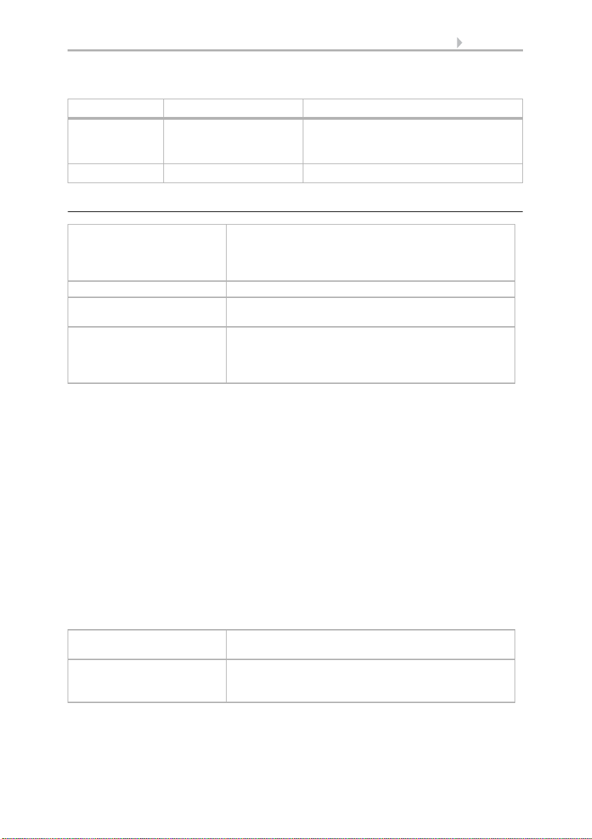
The standard panel can be trimmed on three sides (see
Fig. 1, Page 5)
Minimum width approx. 751 mm
plus the measure needed for mounting on both sides
Minimum depth approx. 405 mm
plus the measure needed for mounting above and
below
5 Installation and start-up
Ventilation Unit WL800 • Version: 28.04.2016 • Errors and technical modifications subject to change without notice.
1.1.3. Colours
Standard colours for ventilator and panel (included in price):
• RAL 9016 Traffic White
• RAL 9006 White Aluminium
• RAL 9007 Grey Aluminium
All other RAL colours are also available at an additional charge (also two-coloured in-
side – outside).
Hinweis: The delivered colour tones are similar to the RAL colours specified. Devia-
tions due to technical reasons are possible. Due to the different nature of the surface
of the panel and ventilator housing, slightly different degrees of lustre can occur.
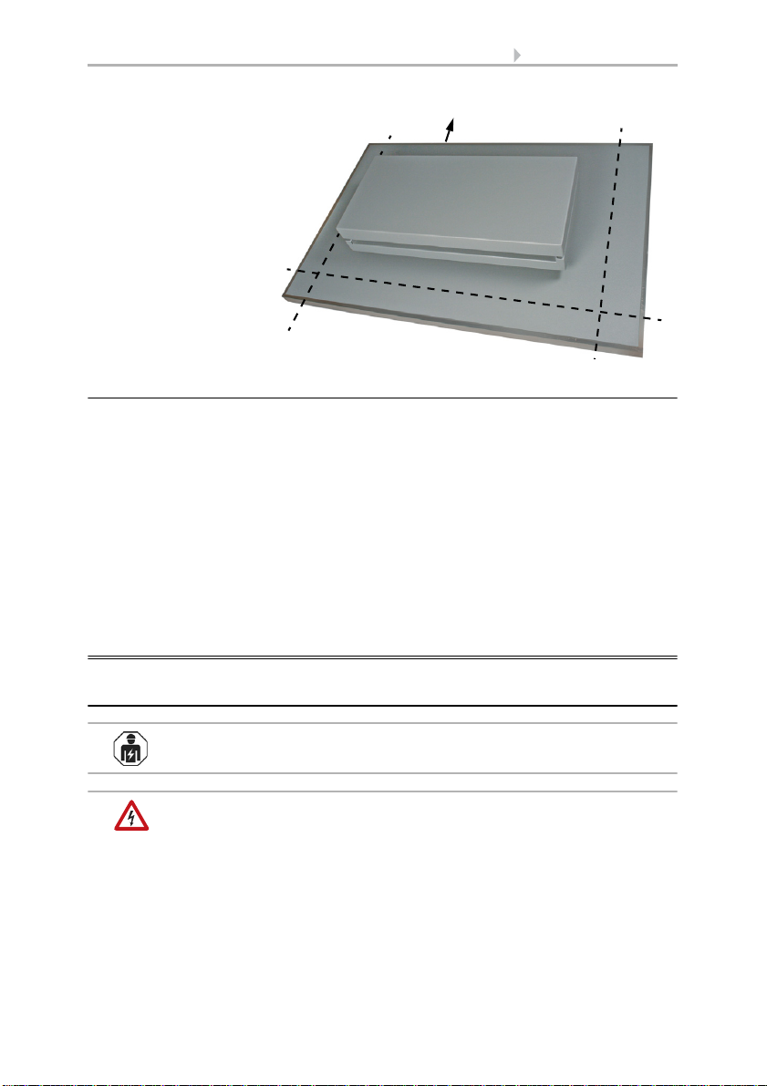
2. Installation and start-up
2.1. Installation notes
Installation, testing, operational start-up and troubleshooting should
only be performed by an electrician.
DANGER!
Risk to life from live voltage (mains voltage)!
There are unprotected live components within the device.
• VDE regulations and national regulations are to be followed.
• Ensure that all lines to be assembled are free of voltage and take
precautions against accidental switching on.
Fig. 1
Trimming of stand-
ard panel
Cable outlet voltage supply

6 Installation and start-up
Ventilation Unit WL800 • Version: 28.04.2016 • Errors and technical modifications subject to change without notice.
• Do not use the device if it is damaged.
• Take the device or system out of service and secure it against
unintentional use, if it can be assumed, that risk-free operation is no
longer guaranteed.
The device is only to be used for its intended purpose. Any improper modification or
failure to follow the operating instructions voids any and all warranty and guarantee
claims.
After unpacking the device, check it immediately for possible mechanical damage. If it
has been damaged in transport, inform the supplier immediately.
The device may only be used as a fixed-site installation; that means only when assem-
bled and after conclusion of all installation and operational start-up tasks and only in
the surroundings designated for it.
Elsner Elektronik is not liable for any changes in norms and standards which may occur
after publication of these operating instructions.
2.2. Notes on wireless equipment
When planning facilities with devices that communicate via radio, adequate radio re-
ception must be guaranteed. The range of wireless control will be limited by legal reg-
ulation and structural circumstances. Avoid sources of interference and obstacles be-
tween receiver and transmitter, that could disturb the wireless communication. Those
would be for example:
• Walls and ceilings (especially concrete and solar protection glazing).
• Metal surfaces next to the wireless participants (e. g. aluminium construction
of a conservatory).
• Other wireless devices and powerful local transmitters (e.g. wireless
headphones), which transmit on the same frequency (868,2 MHz). Please
maintain a minimum distance of 30 cm between wireless transmitters for that
reason.
2.3. Instructions for simultaneous operation of a
non-roomsealed firing installation
Non-roomsealed firing installations are e.g. heating devices operated with gas, oil,
wood or coal, flow heaters, water heaters, cookers and ovens that are supplied with
combustion air from the room where they are installed and that have an exhaust sys-
tem (e.g. chimney) through which the exhaust gas is discharged into the atmosphere.
WARNING!
Danger to life from toxic combustion gases!
If the ventilation unit is operated in exhaust mode simultaneously with
a non-roomsealed firing installation in the same room or area, toxic
combustion gases may be drawn from the chimney or vent into the room, if
there is not enough supply air.
7 Installation and start-up
Ventilation Unit WL800 • Version: 28.04.2016 • Errors and technical modifications subject to change without notice.
• Consult the responsible chimney sweeper. He is able to assess the
complete ventilation area of the apartment and point out measures for secure
air supply (e.g. openings in doors/windows that cannot be closed, safety
contacts on windows/ventilation devices or similar)
When the ventilation unit is running in circulation mode, the simultaneous operation
of a non-roomsealed firing installation is harmless.
2.4. Assembly
The Ventilation Unit WL800 can be installed in any inclination from 0° (flat roof) to
90° (wall mounting). In case of mounting angles from 70° to 90°, the additional option
"wall device" must be ordered (surcharge). In case of mounting on a flat roof, water on
the panel must not exceed the height of 2 cm. The air outlet must face the direction that
is opposite to the weather side.
Leave sufficient distance to walls or ledges when installing the fan so that the blower
unit can be easily removed for disassembly.
• Keep a distance of at least 60mm to the wall so the interior hood can be
removed (ill. 4)
• Leave sufficient room for disassembly of the blower unit. The blower unit is
340mm in length
Please note the instructions and the drawing in chapter Disassembly for maintenance,
page 8.
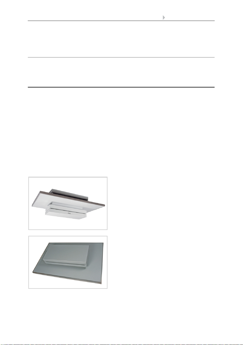
Fig. 2
The smaller ventilator hood with the logo
faces inward.
Fig. 3
When the ventilation unit is installed with an
inclination, the air outlet on the outside must
face downward, so as to prevent water or dirt
from entering (rain, snow, leaves etc.).
Air outlet
DOWNWARD

8 Installation and start-up
Ventilation Unit WL800 • Version: 28.04.2016 • Errors and technical modifications subject to change without notice.
2.4.1. Disassembly for maintenance
It is not necessary to remove the blower unit when installing the
ventilation unit.
The following distances and measurements must be taken into consideration in order
to be able to remove the blower unit from the ventilation unit for servicing:
• Keep a distance of at least 60mm between the internal hood and the wall (Fig.
4).
• Leave sufficient room for disassembly of the blower unit. The blower unit is
340mm in length (Fig. 5)
To remove blower unit for servicing:
1. Remove the screws on the internal hood and pull the hood down on the air
discharge side.
2. Shift the hood approx. 60mm and remove it.
Internal hood
at least
Fig. 4
Keep a distance of at least 60mm to the wall
so the interior hood can be removed.
60 mm
Internal hood
Fig. 5
Remove internal hood and
blower unit.
Blower unit
170mm
340mm

9 Establish wireless connection
Ventilation Unit WL800 • Version: 28.04.2016 • Errors and technical modifications subject to change without notice.
3. Pull the blower unit down parallel to the housing.
2.5. Connection
Connect the mains voltage (230 V AC continuous voltage):
3. Establish wireless connection
To establish the wireless connection, the fan cover does not need to be removed.
4. Set the control unit and/or remote control or the button to teaching mode (observe
the corresponding manual/data sheet).
5. Switch on the power supply to the fan and/or shut off the power supply briefly if
the unit is already supplied with power.
6. The fan will send a "Teach" telegram every 10 seconds for 5 minutes after connect-
ing the power.
7. The wireless connection will be established automatically. The building control
system will display "Device has been taught".
The fan will stop sending "Learn" telegrams once the reply "taught" (for a learning pro-
cess) or a control command (in the event of a power failure during operation) is re-
ceived from a control unit.
4. Maintenance
The function of the unit should be checked by the specialized dealer/installation tech-
nician once a year and the ventilation device cleaned from any dirt. No aggressive de-
tergents must be used for cleaning.
5. Operation with remote control Remo 8
A briefly pressing the arrow keys adjusts the speed of the fan in 10% increments
(10 fan speeds altogether).
Longer pressing of the arrow keys changes the speed continuously. If you release
the key, the speed stops changing.
Note: Radio interference (rarely) may cause the speed to continue changing after the
key is released. In this case, briefly press the key again to stop it.
green-yellow Protective conductor
1 Neutral conductor
2 Outer conductor L1

10 Operation with remote control Remo 8
Ventilation Unit WL800 • Version: 28.04.2016 • Errors and technical modifications subject to change without notice.
Each time the OFF state is reached, the speed change stops automatically, so that a
direct change between exhaust and circulation modes is impossible.
Fan OFF
(stopped,
flap closed)
Circulation air mode
Press
Increase speed
Lower rotation speed
(to OFF)
Fan OFF
Press Exhaust air mode
Lower rotation speed
(to OFF)
Increase speed
Fan OFF
This manual suits for next models
2
Table of contents
Other elsner elektronik Fan manuals


Popular Fan manuals by other brands

Johnson Controls
Johnson Controls FCP-PA-701-NF quick start guide

RUSTA
RUSTA 907511880101 manual

NuAire
NuAire ECOSMART TWINFAN Series Installation and Maintenance

Zehnder Rittling
Zehnder Rittling J.E. StorkAir RPM user manual

Gibbons Fans
Gibbons Fans FP5005 Instruction manual and warranty information

Prem-I-Air
Prem-I-Air EH1854 user manual


