elsner elektronik Sewi KNX L User manual
Sensor Sewi KNX L 1
Sensor Sewi KNX L • Version: 25.01.2021 • Technical changes and errors excepted. • Elsner Elektronik GmbH • Sohlengrund 16 • 75395 Ostelsheim • Germany • www.elsner-elektronik.de • Technical Service: +49 (0) 7033 / 30945-250
EN
Sewi KNX L
Indoor brightness sensor
Technical specifications and installation instructions
Item numbers 70395 (white), 70695 (jet black)
1. Description
The Sensor Sewi KNX L for the KNX bus system captures the brightness in the
room. The measurement value can be used for the control of limit-dependent swit-
ching outputs. States can be linked via AND logic gates and OR logic gates. Multi-
function modules change input data as required by means of calculations, querying
a condition, or converting the data point type.
Functions:
•Brightness measurement with brightness control
•Threshold values can be adjusted per parameter or via communication
objects
•8 AND and 8 OR logic gates, each with 4 inputs. All switching events as
well as 16 logic inputs in the form of communications objects can be used as
inputs for the logic gates. The output of each gate can be configured
optionally as 1-bit or 2 x 8-bit
•8 multi-function modules (computers) for changing the input data by
calculations, by querying a condition or by converting the data point type
Configuration is made using the KNX software ETS. The product file can be dow-
nloaded from the Elsner Elektronik website on www.elsner-elektronik.de in the
“Service” menu.
1.0.1. Scope of delivery
• Brightness sensor
1.1. Technical data
The product conforms with the provisions of EU directives.
2. Safety and use instructions
2.1. General installation notes
Installation, testing, operational start-up and troubleshooting should
only be performed by an electrician.
CAUTION!
Live voltage!
There are unprotected live components inside the device.
• When planning and installing electrical systems, observe the
applicable directives, regulations and provisions of the
respective country.
• Ensure that the device or system can be disconnected. During
installation, disconnect all cables from the power supply and
take safety precautions against unintentional switch-on.
• Do not use the device if it is damaged.
• Take the device or system out of service and secure it against
unintentional use, if it can be assumed, that risk-free operation is
no longer guaranteed.
The device is only to be used for the intended purpose described in this manual. Any
improper modification or failure to follow the operating instructions voids any and
all warranty and guarantee claims.
After unpacking the device, check it immediately for possible mechanical damage.
If it has been damaged in transport, inform the supplier immediately.
The device may only be used as a fixed-site installation; that means only when as-
sembled and after conclusion of all installation and operational start-up tasks and
only in the surroundings designated for it.
Elsner Elektronik is not liable for any changes in norms and standards which may
occur after publication of these operating instructions.
3. Installation
3.1. Installation location and preparation
Install and use only in dry interior rooms! Avoid condensation.
The Sensor Sewi KNX L is installed surface mounted on walls or ceilings.
3.2. Connection
For installation and wiring at the KNX connection, the
provisions and standards applicable to SELV circuits must be
complied with!
The Sensor Sewi KNX L is surface-mounted but at the same time can also be scre-
wed to a flush-mounted socket.
If the Sensor Sewi KNX L is installed on a flush-mounted socket, it must not con-
tain any wiring with 230 V.
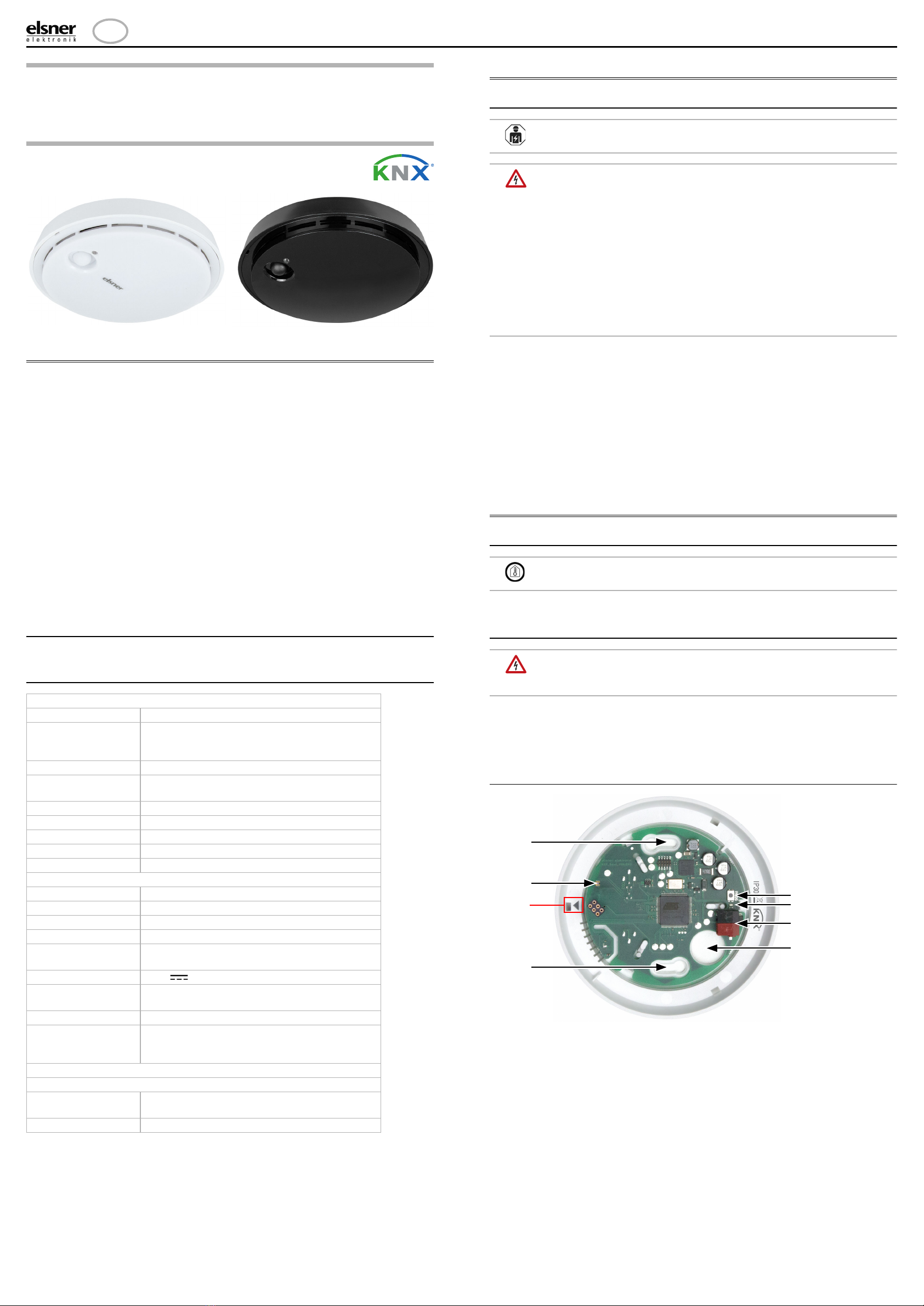
3.2.1. Layout of the circuit board
General:
Housing Plastic
Colours • White similar to signal white RAL 9003
(skirting)/ grey white RAL 9002 (cover)
• Jet black RAL 9005
Assembly Surface, wall or ceiling installation
Dimensions Ø x
height
approx. 105 mm x approx. 32 mm
Degree of protection IP 30
Weight approx. 45 g
Ambient temperature -25…+80°C
Ambient humidity 5...95% RH, non-condensing
Storage temperature -25…+85°C
KNX bus:
KNX medium TP1-256
Configuration mode S-Mode
Group addresses max. 2000
Assignments max. 2000
Communication
objects
189
Nominal voltage KNX 30 V SELV
Power consumption
KNX
max. 10 mA
Connection KNX plug terminals
Duration after bus
voltage restoration
until data is received
approx. 5 seconds
Sensors:
Brightness sensor:
Measurement range 0 lux … 2,000 lux (higher values can be measu-
red and output)
Resolution 1 lux at 0…2,000 lux
Fig. 1
1 a+b Long holes for mounting (hole distance 60 mm)
2 Brightness sensor
3 Programming button
4 Programming LED
5KNX-terminalBUS+/-
6 Cable bushing
A Mark for aligning the cover
1a
A
1b
3
5
6
4
2
Sensor Sewi KNX L 2
Sensor Sewi KNX L • Version: 25.01.2021 • Technical changes and errors excepted. • Elsner Elektronik GmbH • Sohlengrund 16 • 75395 Ostelsheim • Germany • www.elsner-elektronik.de • Technical Service: +49 (0) 7033 / 30945-250
3.2.2. Assembly
4. Commissioning
The brightness sensor must not get dirty, be painted over or covered.
After the bus voltage has been applied, the device will enter an initialisation phase
lasting approx. 5 seconds. During this phase no information can be received or sent
via the bus.
4.1. Addressing the equipment
The individual address is assigned via the ETS. For this purpose there is a button
with a control LED on the unit (Fig. 1, No. 3+4).
The equipment is delivered with the bus address 15.15.255. Another address can be
programmed using the ETS.
5. Maintenance
As a rule, it is sufficient to wipe the device with a soft, dry cloth twice a year.
6. Disposal
After use, the device must be disposed of or recycled in accordance with the legal
regulations. Do not dispose of it with the household waste!
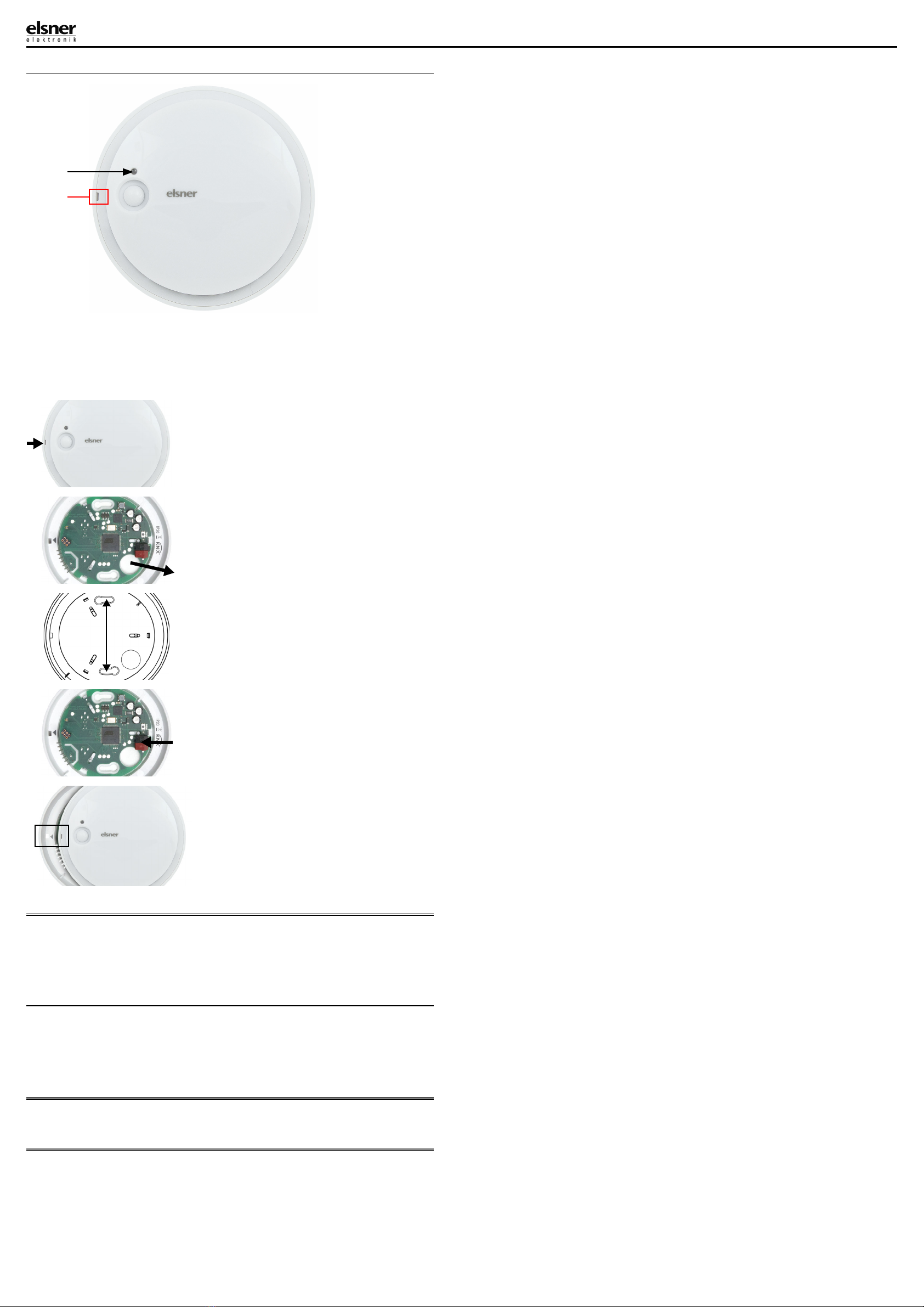
1
Fig. 2 Housing from the outside
1 Brightness sensors
A Recess to open the housing
A
Fig. 3
Open the housing. To do this, carefully
lift the cover from the skirting. Start at
the recess, e.g. with a flat-head screw-
driver.
Fig. 4
Lead the bus cable through the cable
bushing in the skirting.
Fig. 5
Screw the skirting to the wall or the
ceiling.
Hole distance 60 mm.
60 mm
Fig. 6
Connect the KNX bus to the KNX ter-
minal.
Fig. 7
Close the housing by positioning the
cover and snapping it into place. To do
this, align the recess on the cover to
the marking on the skirting (the pre-
sence sensor must protrude through
the opening in the cover).
Other manuals for Sewi KNX L
1
This manual suits for next models
2
Popular Lighting Equipment manuals by other brands

Eliminator Lighting
Eliminator Lighting INDY HEX PAR user guide

Feniex
Feniex COBRA MINI M-2111 Installation and operational guide

Avlite
Avlite AV-HLI2 Installation & service manual

NVC
NVC KANSAS PRO instructions

INNOVAPLAS
INNOVAPLAS Self-Latching Assembly manual

Acuity Brands Lighting
Acuity Brands Lighting CPHB quick start guide


