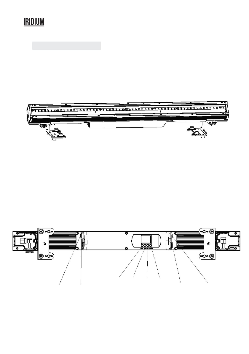
connect several pieces of lights with DMX cable and control
them with the control console.
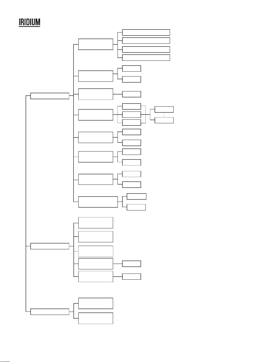
1) “XXX” will be showed in “Address”, "XXX” means the Address 001-512. You can press “UP” or
“DOWN”to select the address you desired.
means 5 kinds of DMX Channels Modes.
You can press “UP” or “DOWN” to select the Channel Mode you desired.
In this menu,you can choose the mode you desired.
you can see 4 items as below:
2) Stage/TV
3) Architec
4) Theatre
this menu,you can choose the DMX signal you desired.
1. Press “ENTER” and then press “UP” or “DOWN” to “DMX STATE”.
2. Press “ENTER” and you can choose “BLACKOUT” or “DMX HOLD”;”BLACKOUT” means cut off
the DMX signal and “DMX HOLD” means connect DMX signal.
In this menu, you can choose one light as the MASTER light and other lights in
SLAVE Mode will run follow the MASTER light.
2. Press “ENTER” and “SLAVE” will be showed, then press “ENTER” to choose.
In this menu, you can choose your desired
Mode and adjust the running
2. Press “ENTER” you can see 2 items as below:
1) SPEED - It provides “01-31” for you choose.
1. DMX means the light is in the DMX
means the light is in the
In this menu,you can choose the modes you need.
you can see 8 items as below:
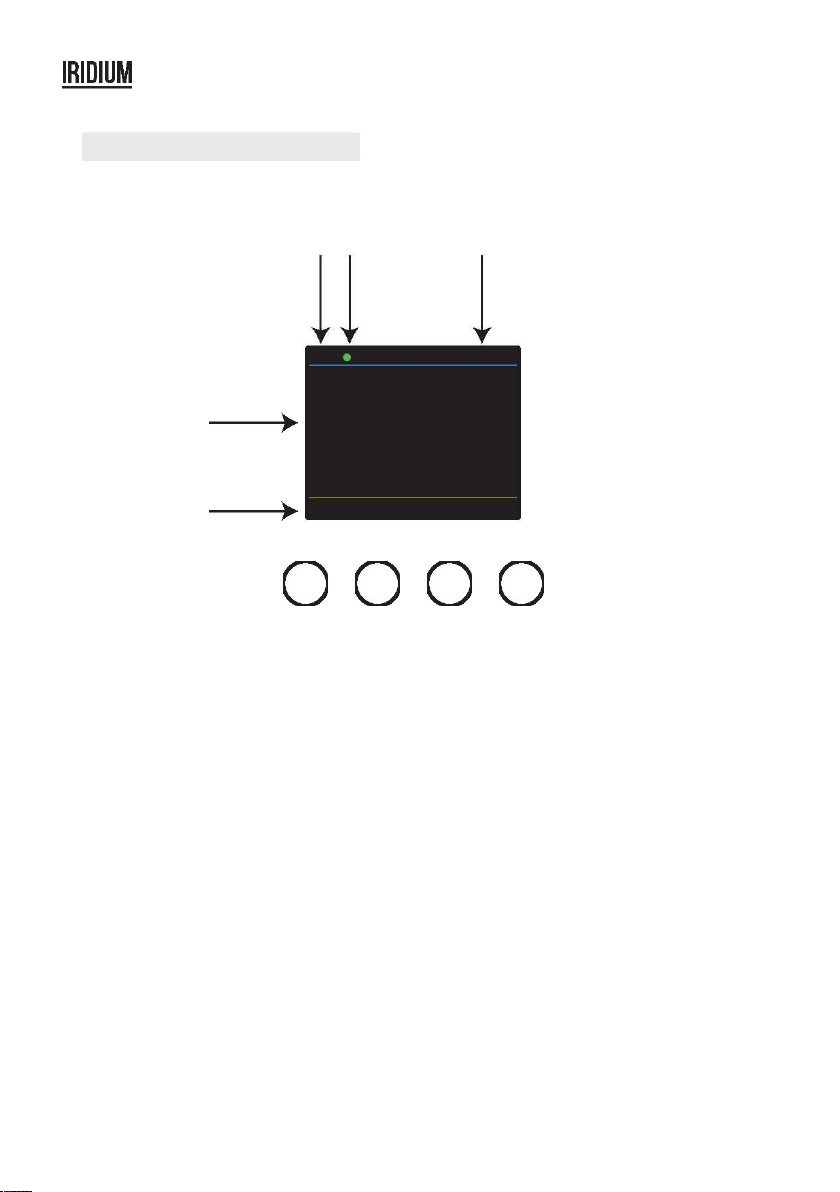
The color of the point shows the
condition of signal transmission. Green represents
the good condition, while red represents the signal is interrupted.
3. The item shows the working temperature of the light.When the working temperature
exceeds the max temperature,the color of the letters and number will change from white
to yellow.
8) STROBE - You can choose “0-20” in this menu.
this menu, you can choose the brightness you
1. Press “ENTER” and then press “UP” or “DOWN” to “CCT”.
This item shows the menu you selected.
This item shows the condition of key lock.
open.And “Key lock off” means the key lock is close.
In this menu, you can adjust the values of the function.
1. Press “ENTER” and then press “UP” or “DOWN” to “SET UP”.
and there has 6 options then press
choose the options and press
or “DOWN” to choose the value you desired as below:
1) IR - You can press “ON” or “OFF” to choose whether you need to controll by this mode.
2) Dimmer All - You can adjust the brightness of colors.
4) Key Lock - You can choose “ON” or “OFF” to make the Key Lock turn on or off.
5) Display - You can choose “ON” or “30s” to make the position of the light screen.
6) Max temp - You can set the your desired Max working temperature of the light with passcode in this
menu.When the working temperature beyond max temperature of default settings, the color of letter
“Temp XX” will show the color from white to yellow.Meanwhile, the light will adjust the working
temperature automatically.
CHANNEL
003
Activate ID addressing in each fixture by setting panel function
“Settings” to “ID ON/OFF” to “ON” For every DMX 512 starting address the user can set 66
separate ID addresses. Set ID addresses in each fixture by setting panel function “ ID
address” to incremental values.(l.e. 1, 12, 24, 36 etc...) “Settings” to “address” to “01~66”.
CHANNEL
010
CHANNEL
022
DMX CHANNEL CHANNEL
036
DMX address: 001 DMX address: 001 DMX address: 001 DMX address: 012 DMX address: 012 DMX address: 012
ID address: 01 ID address: 02 ID address: 03 ID address: 01 ID address: 02 ID address: 03
CHANNEL
050
DMX MODE CHANNEL
092
ADDRESS
001
ADDRESS
512
The figure above shows a simple DMX layout which has used three units at each DMX address. The
three units have different ID addresses which allows the user to collectively control the whole group of
units at that DMX address by setting Channel 10 to 0, or to control each unit independently by first
selecting the DMX address and then by using Channel 11 to locate the target ID address. (Note that
when using ID addresses it is also
possible to activate ADAS which allows for even more option with
DMX addressing and control.
DMX Hold
Black out
DMX State
SLAVE MODE
Auto
Slave
Auto
1
31
1
Speed
10
Master Slave Slave Slave Slave Slave
GREED
BLUE
0
255
which involves the program you have edited in EDIT
and want to upload, in Master mode,and others in Slave mode.
Then,connect all the lights with DMX cables.Finally,select the UPLOAD
menu of the Master light and press ENTER.All the programs edited in the
Master light will be uploaded to the Slave lights.
STATIC COLOR
0
COLOR
51
0
STROBE
20