Elsner Intra-Sewi TWIN L-Pr Installation manual

Sensor Intra-Sewi TWIN TH-L-Pr and Intra-Sewi TWIN L-Pr 1
Sensor Intra-Sewi TWIN TH-L-Pr and Intra-Sewi TWIN L-Pr • Version: 09.08.2019 • Technical changes and errors excepted. • function Technology AS • Norway • +47 55 38 50 80 • www.function-technology.com
EN
Intra-Sewi TWIN L-Pr and
Intra-Sewi TWIN TH-L-Pr
Brightness and Presence Detectors
Technical specifications and installation instructions
1. Description
The Sensor Intra-Sewi TWIN L-Pr for the TWIN building bus system captures
brightness and motion in a room. Two Intra-Sewi TWIN can be connected at the
same time to one controller.
The Sensor Intra-Sewi TWIN TH-L-Pr additionally measures the temperature and
the air humidity.
Functions:
•Brightness measurement with brightness control
• Motion detection
Additional functions Intra-Sewi TWIN TH-L-Pr:
• Measuring the temperature and air humidity (relative, absolute)
1.0.1. Scope of delivery
• Sensor
• Pre-assembled clamps for false ceiling installation
• Support ring for connector socket installation
For socket installation you will need in addition (not supplied):
• Socket Ø 60 mm, 42 mm deep
1.1. Technical data
The product is compliant with the provisions of the EU guidelines.
1.1.1. *Measuring accuracy
Deviations in measured values due to interfering sources (see chapter installation
location) must be corrected in the MultiController TWIN application in order to
achieve the specified accuracy of the sensor (offset).
During the Temperature measurement, the self-heating of the device is taken into
consideration by the electronics. It is compensated by the software, therefore the di-
splayed/output indoor temperature measuring value is correct.
2. Installation and start-up
2.1. Installation notes
Installation, testing, operational start-up and troubleshooting should
only be performed by an electrician.
CAUTION!
Live voltage!
There are unprotected live components inside the device.
• National legal regulations are to be followed.
• Ensure that all lines to be assembled are free of voltage and take
precautions against accidental switching on.
• Do not use the device if it is damaged.
• Take the device or system out of service and secure it against
unintentional use, if it can be assumed, that risk-free operation is no
longer guaranteed.
The device is only to be used for its intended purpose. Any improper modification
or failure to follow the operating instructions voids any and all warranty and gua-
rantee claims.
After unpacking the device, check it immediately for possible mechanical damage.
If it has been damaged in transport, inform the supplier immediately.
The device may only be used as a fixed-site installation; that means only when as-
sembled and after conclusion of all installation and operational start-up tasks and
only in the surroundings designated for it.
function Technology AS is not liable for any changes in norms and standards which
may occur after publication of these operating instructions.
2.2. Installation location
Install and use only in dry interior rooms! Avoid condensation.
The Sensor is installed in a false ceiling or a standard connection socket (Ø 60 mm,
42 mm deep).
The device must be installed on the ceiling, so that the movement capturing takes
place from above. Make sure that the desired area is covered by the sensor's cover-
age angle and that no obstacles obstruct the recording.
When selecting an installation location for Intra-Sewi TWIN TH-L-Pr, please ensu-
re that the measurement results of temperature and humidity are affected as litt-
le as possible by external influences. Possible sources of interference include:
• Direct sunlight
• Draughts from windows and doors
• Draughts from ducts coming from other rooms or the outdoors
• Warming or cooling of the building structure on which the sensor is mounted,
e.g. due to sunlight, heating or cold water pipes
• Connection lines and empty ducts which lead from warmer or colder areas to
the sensor
Measurement variations from such sources of interference must be corrected in the
application program for the MultiController in order to ensure the specified accuracy
of the sensor (offset).
2.2.1. Coverage area of the motion detector
Angle of coverage: approx. 94° × 82°
Range: approx. 5 m
Segmentation of the coverage area
Size of the coverage area
Housing Plastic, glass
Colour similar to pure white RAL 9010
Assembly built-in, in false ceiling or connector socket
Protection category IP 30
Dimensions Ø approx. 80 mm;
height above wall approx. 5 mm
height in wall (installation) approx. 31 mm (incl.
clamps)
Total weight approx. 50 g
Ambient temperature Operation -20…+60°C, storage -20…+70°C
Ambient humidity max. 95% RH, avoid condensation
Operating voltage TWIN bus voltage
Bus current max. 10 mA
Data output TWIN +/- bus plug-in terminal
BCU type Integrated microcontroller
PEI type 0
Brightness sensor:
Measurement range 0 lux … 2,000 lux (higher values can be measu-
red and output)
Resolution 1 lux at 0…2,000 lux
Accuracy ±15% of the measurement value at 30 lux …
2,000 lux
Motion sensor:
Coverage angle approx. 94° × 82° (see also Coverage area of the
motion detector)
Range approx. 5 m
Temperature sensor (only Intra-Sewi TWIN TH-L-Pr):
Measurement range -20°C … +60°C
Resolution 0.1°C
Accuracy* ±0.7°C at -20°C...-10°C
±0.5°C at -10°C...+60°C
Humidity sensor (only Intra-Sewi TWIN TH-L-Pr):
Measurement range 0% rH … 100% rH
Resolution 0.1% rH
Accuracy ± 7.5% rH at 0% … 10% rH
± 4.5% rH at 10% … 90% rH
± 7.5% rH at 90% … 100% rH
Item numbers
66111 Intra-Sewi TWIN L-Pr
66121 Intra-Sewi TWIN TH-L-Pr
Distance Length Width
2.50 m approx. 5.40 m approx. 4.30 m
3.50 m approx. 7.50 m approx. 6.10 m
Fig. 1
width
length
Orientation of the
support ring for so-
cket installation
Sensor Intra-Sewi TWIN TH-L-Pr and Intra-Sewi TWIN L-Pr 2
Sensor Intra-Sewi TWIN TH-L-Pr and Intra-Sewi TWIN L-Pr • Version: 09.08.2019 • Technical changes and errors excepted. • function Technology AS • Norway • +47 55 38 50 80 • www.function-technology.com
2.3. Installation of the sensor
2.3.1. Installation in false ceiling
Connect the bus line to the TWIN terminal (blue/white).
Place the device in the installation opening in the ceiling. For this, fold the clamps
upwards and guide the device through the installation opening with the clamps first.
The device is automatically fixed by the clamps.
2.3.2. Installation in connector socket
Before socket installation, remove the clamps for the false ceiling installation.
Screw the support ring onto the socket. Pay attention to the orientation as shown in
the chapter Coverage area of the motion detector.
Connect the bus line to the TWIN terminal (blue/white).
Clamp the device in the support ring so that the springs on the device snap over the
tabs of the support ring.
2.3.3. Back view: connection
The connection is made with the TWIN terminal (red/black) to TWIN TP.
2.3.4. Front view
2.4. Notes on mounting and commissioning
Never expose the device to water (e.g. rain) or dust. This can damage the electro-
nics. You must not exceed a relative humidity of 95%. Avoid condensation.
The airing lamella must not be closed or covered. The device must not be painted
over.
After the bus voltage has been applied, the device will enter an initialisation phase
lasting a few seconds. During this phase no information can be received or sent via
the bus.
The motion sensor has a start-up phase of approx. 15 seconds during which no mo-
tion detection takes place.
3. Maintenance
The brightness and movement sensor and the airing lamella must not get dirty or
covered. As a rule, it is sufficient to wipe the device with a soft, dry cloth twice a ye-
ar.
A
Fig. 2
1 Clamps for installation in false ceiling
A Height in wall (built-in): approx. 31 mm
B Space behind the false ceiling, necessary for insertion (clear dimensi-
on): approx. 31 mm
C Maximum wall thickness: 20 mm
D Hole size for installation: 50...65 mm
B
C
D
1
Fig. 3: Support ring
1Tabs
1
1
Fig. 4
Connector socket with Ø 60 mm, 42 mm deep.
1 Support ring, screwed to the socket
2 Springs hold the device firmly on the support ring
2
1
2
Fig. 5
1 Clamps for installation in
false ceiling
2 Springs for installation in
support ring
3TWINterminal
1
3
2
1
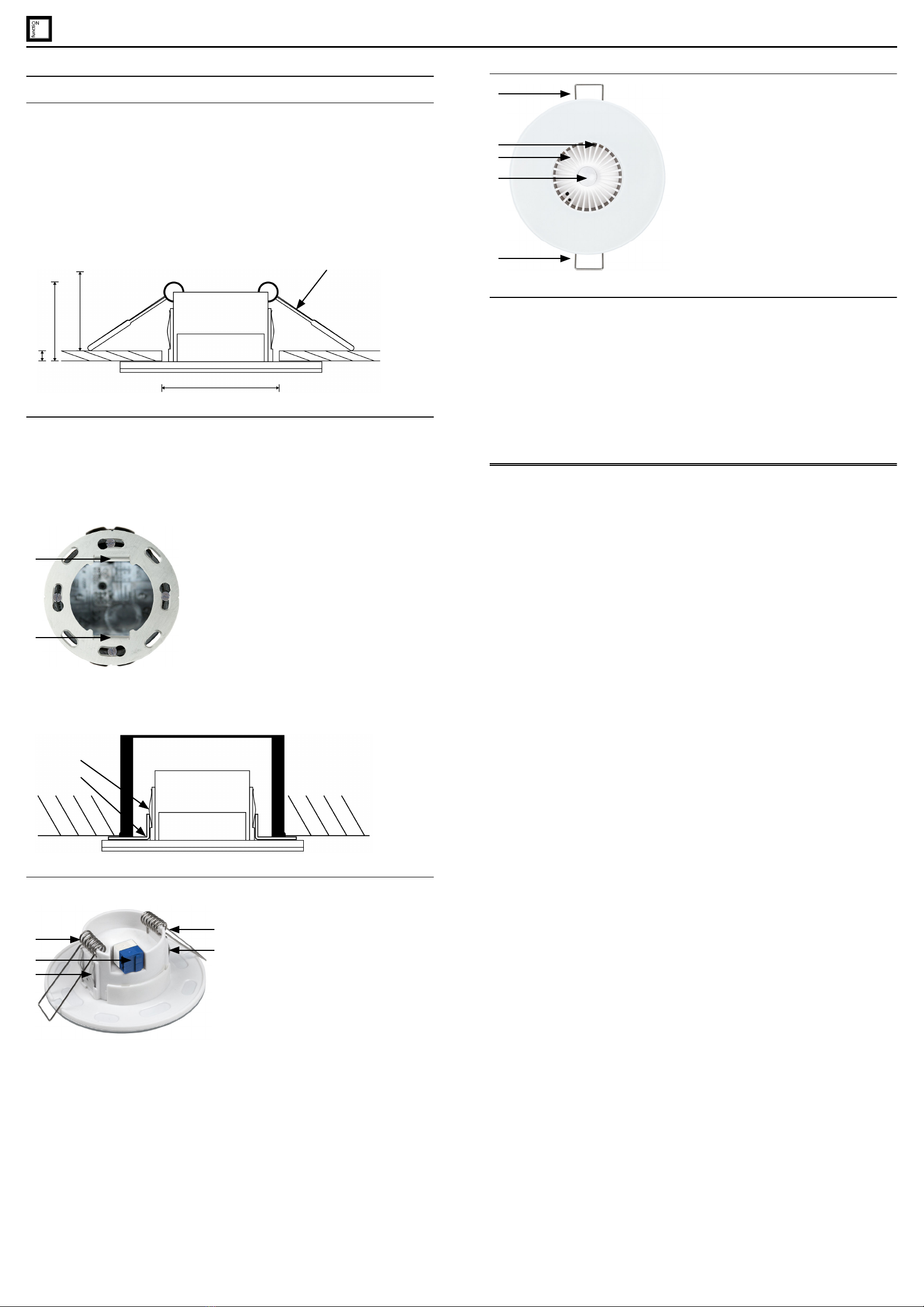
1Fig. 6
1 Clamps for installation in
false ceiling
2 Brightness sensor
3 Airing lamella
4 Motion sensor
3
4
1
2
This manual suits for next models
3


