SENKO SI-100 User manual

MODEL: SI-100
(Fixed Gas Detector)
Manual
SI-100 MANUAL
2
Warning
➢Remove any debris on the surfaces of the sensor part before use.
➢Test regularly whether the alarms go off properly.
➢Use the device under the conditions instructed, including the temperature, humidity and
pressure range. The use out of the instructed conditions may cause malfunction or failure.
➢The sensors inside the device may indicate the gas concentration differently according to the
environment such as temperature, pressure and humidity. Make sure to calibrate the detector
under the same or similar environment to the specification.
➢Severe shock to the device may cause failures of the device or sensors.
➢Alarm values are set according to international standards. Therefore, the values must be changed
by an authorized expert.
Caution
➢Use the device after reading this manual thoroughly.
➢This product is not a gas analyzer, but a gas detector.
➢If calibration failure occurs continuously, stop using the equipment and contact the manufacturer.
Warranty
We, SENKO CO., LTD warrant replacement or repair for the products of SI series for 24 months from the
shipment date of the product(s). However, the parts, whose life can be shortened by use, such as sensors,
batteries and lamps are not under the warranty. Also, Free repair and replacement is not available in case of
purchases of our products through unauthorized channels, mechanical damage and deformation by user’s
misuse, and calibration and replacements of parts without following the instruction in the manual. If any defect
or quality problem occurs to the products during the warranty period, the user should notify it to the
manufacturer. In this case, all the expenses except freight cost are paid by SENKO. Repair, replacement and
freight cost for the products, whose warranty is already over, are paid by the user. SENKO CO., LTD does not
have any responsibility for indirect, or accidental loss which occurs while using our products, and the warranty
is limited to the exchange of parts and products. The warranty is subject to the users who have bought
products from the authorized agency and office appointed by SENKO CO., LTD, and warranty repairs must be
made through the designated A/S center of SENKO CO., LTD with a skilled technician.
WARNING
Read this manual carefully before using the instrument. The instrument
will perform as designed only if it is used and maintained in accordance
with the manufacturer's instruction. Otherwise, it could fail to perform as
designed and persons who rely on this instrument for their safety could
sustain serious personal injury or death.

SI-100 MANUAL
3
Table of Contents
1. Introduction........................................................................................................................................................................4
1.1. Specification..........................................................................................................................................................4
1.2. Sensor List ..............................................................................................................................................................5
2. Instrument Overview.....................................................................................................................................................6
3. How to install ....................................................................................................................................................................7
3.1. How to fix...............................................................................................................................................................7
3.2. How to open and wire ....................................................................................................................................7
3.2.1 Separating Cover from Gas Detector Body ....................................................................................7
3.2.2 Gas Detector Wiring Diagram................................................................................................................8
4. Measuring Mode..............................................................................................................................................................9
4.1. Gas Detector Initial Operation....................................................................................................................9
4.1.1 Initial Screen Explanation ...................................................................................................................... 10
4.2. Set Display .......................................................................................................................................................... 10
4.2.1 Description of Set Display..................................................................................................................... 10
4.3. Advanced setting............................................................................................................................................. 11
4.4. How to modify the settings [Flow chart].......................................................................................... 12
4.5. Zero calibration & Span calibration ..................................................................................................... 13
4.5.1 How to connect Calibration cap ........................................................................................................ 13
4.5.2 Calibration Mode Explanation............................................................................................................. 13
4.5.3 How to enter Calibration Mode......................................................................................................... 14
5. Certificate.......................................................................................................................................................................... 15

SI-100 MANUAL
4
1. Introduction
1.1. Specification
✓Various sensors can be applied
✓Easy operation with a magnetic bar
✓Large digital LCD embedding white backlight
✓Explosion-proof & Water/Dust-proof structure
✓Automatic calibration function
✓Long-distance transmission by 4-20mA output

SI-100 MANUAL
5
1.2. Sensor List
Gas
Sensor
Range
A1
A2
Resolution
Oxygen
O2
Electrochemical
0~30%Vol
19.0%vol
23.0%vol
0.1%vol
Carbon Monoxide
CO
Electrochemical
0~500ppm
30ppm
60ppm
1ppm
Sulfur Dioxide
SO2
Electrochemical
0~20ppm
2ppm
5ppm
0.1ppm
Hydrogen
H2
Catalytic
0~100%LEL
15%LEL
50%LEL
1%LEL
Hydrogen
H2
Electrochemical
0~1000ppm
100ppm
500ppm
within 5ppm
Hydrogen Sulfide
H2S
Electrochemical
0~500ppm
10ppm
15ppm
1ppm
Combustible
-
Catalytic
0~100%LEL
15%LEL
50%LEL
1%LEL
Combustible
-
IR
0~100%LEL
15%LEL
50%LEL
1%LEL
Ammonia
NH3
Electrochemical
0~100ppm
25ppm
35ppm
1ppm
Acetylene
C2H2
Catalytic
0~100%LEL
15%LEL
50%LEL
1%LEL
Ethanol
C2H6O
Catalytic
0~100%LEL
15%LEL
50%LEL
1%LEL
Toluene
C7H8
IR
0~100%LEL
15%LEL
50%LEL
1%LEL
Toluene
C7H8
Catalytic
0~100%LEL
15%LEL
50%LEL
1%LEL
Methane
CH4
IR
0~100%LEL
15%LEL
50%LEL
1%LEL
Methane
CH4
Catalytic
0~100%LEL
15%LEL
50%LEL
1%LEL
Chlorine
Cl2
Electrochemical
0~5ppm
0.5ppm
1.0ppm
0.1ppm
Chlorine
Cl2
Electrochemical
0~20ppm
0.5ppm
1.0ppm
0.1ppm
Carbon Dioxide
CO2
IR
0~2000ppm
1000ppm
1500ppm
3ppm
Carbon Dioxide
CO2
IR
0~5000ppm
3000ppm
5000ppm
8ppm
Carbon Dioxide
CO2
IR
0~5%Vol
0.5%vol
3%vol
0.1%vol
Hydrogen Chloride
HCl
Electrochemical
0~10ppm
1ppm
2ppm
0.1ppm
VOC
VOC
PID
0~1000ppm
50ppm
100ppm
within 3ppm
Xylene
C8H10
IR
0~100%LEL
15%LEL
50%LEL
1%LEL
Hydrogen peroxide
H2O2
Electrochemical
0~10ppm
1ppm
2ppm
0.1ppm
Nitrogen Dioxide
NO2
Electrochemical
0~20ppm
3ppm
5ppm
0.1ppm
Ethylene oxide
C2H4O
Electrochemical
0~30ppm
1ppm
2ppm
0.1ppm
Ethylene
C2H4
Catalytic
0~100%LEL
15%LEL
50%LEL
1%LEL
Nitrogen Monoxide
NO
Electrochemical
0~100ppm
25ppm
50ppm
1ppm
Hydrogen fluoride
HF
Electrochemical
0~5ppm
0.5ppm
1ppm
0.1ppm

SI-100 MANUAL
6
2. Instrument Overview
1. OK/ERR LED (Power & Operation)
2. LOW Alarm (1st alarm)
3. HIGH Alarm (2nd alarm)
4. Sensor Housing and Sensor Part
5. Buttons (Use a Magnetic bar)
1
2
3
4
5

SI-100 MANUAL
7
3. How to install
Installing a detector at a site, opening the cover of a detector, or operating it may cause fire or
explosion depending on the environment. Therefore, you should proceed with your work after turning off
the power and examining whether explosive residual gas is around you or not.
3.1. How to fix
You can easily install a detector on a wall or ceiling like the above drawing by using M8 Bolts or other bolts.
3.2. How to open and wire
3.2.1 Separating Cover from Gas Detector Body
➢Use a screwdriver to fasten the bolt (for
preventing separating of the Cover from the
body) of the enlarged picture on the side and
turn it counterclockwise by two or three turns.
Then hold the cover of the gas monitor and
turn it counterclockwise to remove the Cover.
SI-100 MANUAL
8
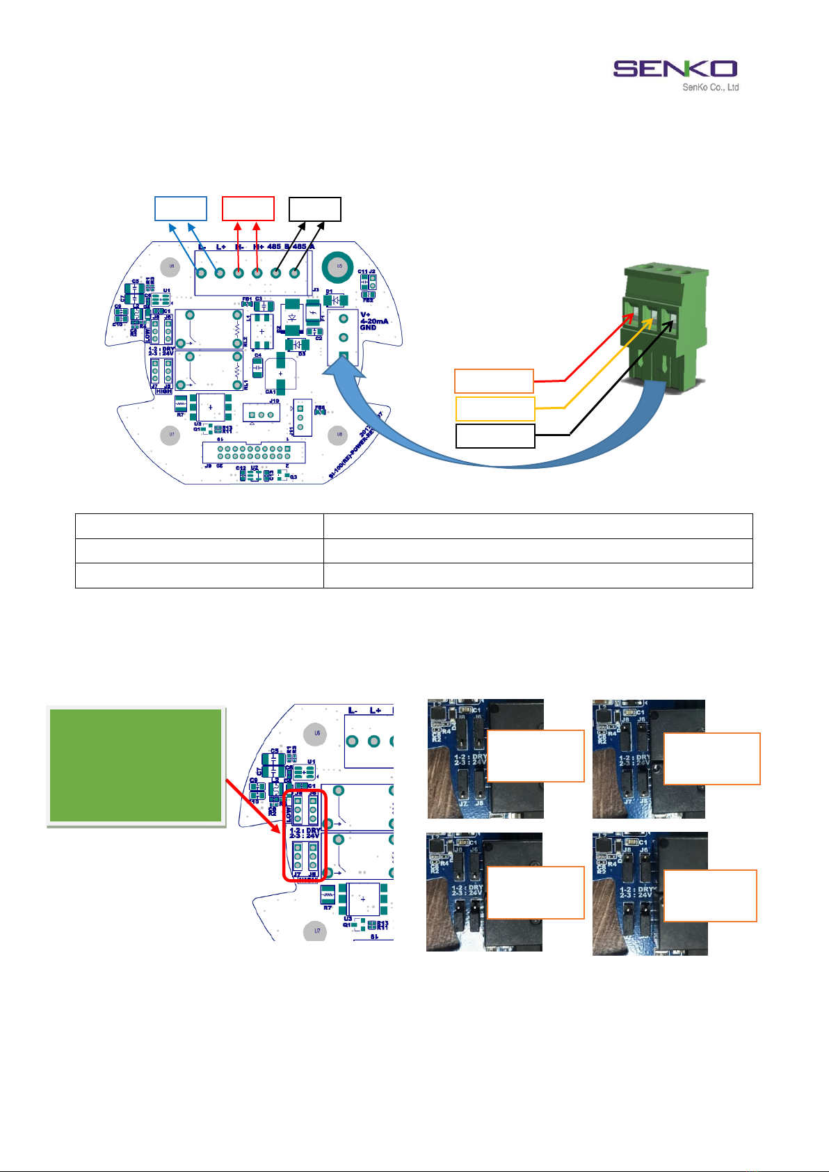
3.2.2 Gas Detector Wiring Diagram
L
Contact output in LOW alarm (DRY or DC 24V)
H
Contact output in HIGH alarm (DRY or DC 24V)
485
RS 485+ Telecommunication output
Normal : Dry
1-2 pin connect : Dry
2-3 pin connect : 24V
LOW : DRY
HIGH : DRY
LOW : DRY
HIGH : 24V
LOW : 24V
HIGH : DRY
LOW : 24V
HIGH : 24V
DC 24V
4~20 mA
GND
L
H
485

SI-100 MANUAL
9
4. Measuring Mode
4.1. Gas Detector Initial Operation
When this gas detector repeatedly fails to initiate measuring mode, first you should check the conditions
of the connection between gas sensors and the detector. When it is impossible for the detector to initiate
measuring mode even when the connection to the sensors is proper, the gas detector should require checks
and repairs. Therefore, please contact SENKO CO., LTD or your supplier.
Power supply
Showing
Version
Failing to
initiate
measuring
mode
Counting for
30 seconds
Entering
Measuring
mode
Gas Sensor Connection Pin
(When this gas monitor fails to
initiate measuring mode, you need to
check whether pins are connected
correctly.)
SI-100 MANUAL
10
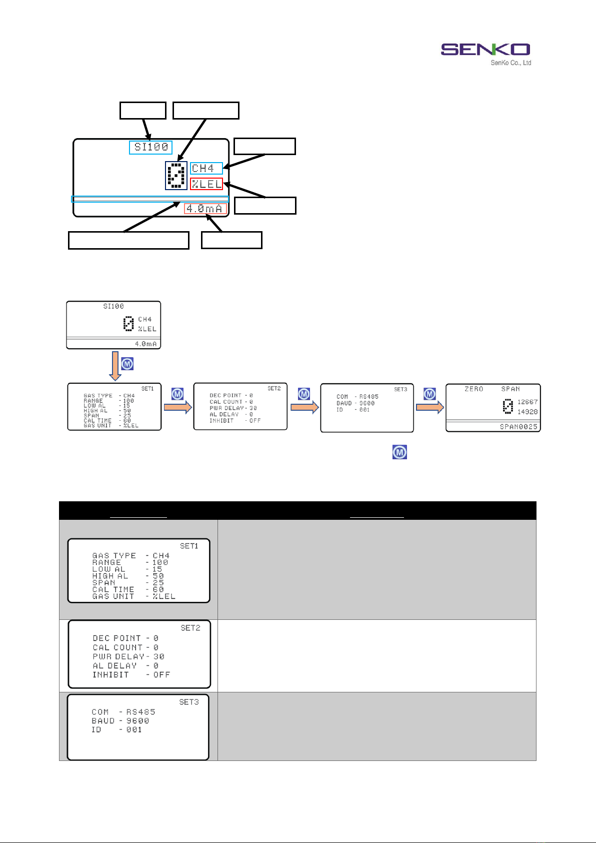
4.1.1 Initial Screen Explanation
4.2. Set Display
The displays are sequentially shown whenever you press each mode key ( ) by using a magnetic bar.
4.2.1 Description of Set Display
LCD Display
Description
➢GAS TYPE: measuring gas, automatic changes of related
information (Range, Low&High Alarm, Span, Unit and point, etc.)
➢RANGE: maximum measurable range
➢LOW AL: LOW (1st) alarm setting values
➢HIGH AL: HIGH (2nd) alarm setting values
➢SPAN: calibration gas concentration
➢CAL TIME: required calibration time
➢GAS UNIT: unit of measuring gas (%VOL, PPM or %LEL)
➢DEC POINT: decimal point for measuring gas concentration
➢CAL COUNT: No. of Span calibration (0-100), not able to change
➢PWR DELAY: initial delay time settings in power supply
➢AL DELAY: delay time settings for alarm occurrence
➢INHIBIT: settings for holding alarm and current output
➢COM: communication method (RS485 or HART or NONE)
➢BAUD: communication speed (baud rate) settings (9600, 19200,
38400)
➢ID : ID settings (0~254)
Model
Gas Type
Unit
Concentration
4-20mA
Bar graph (concentration)

SI-100 MANUAL
11
4.3. Advanced setting
➢Press MODE key ( ) for 2 seconds by using the magnetic bar in Set Display to enter Advanced
setting.
➢Press MODE key ( ) by using the magnetic bar in Advanced setting screen, in order to go to
another menu.
➢Press DOWN key ( ) by using the magnetic bar to go back to the main menu (SET 1, 2 or 3).
➢Without magnetic operation for 60 seconds, the display returns to the main menu (SET 1, 2 or 3).
PUSH (2s)
PUSH (2s)
PUSH (2s)
SI-100 MANUAL
12
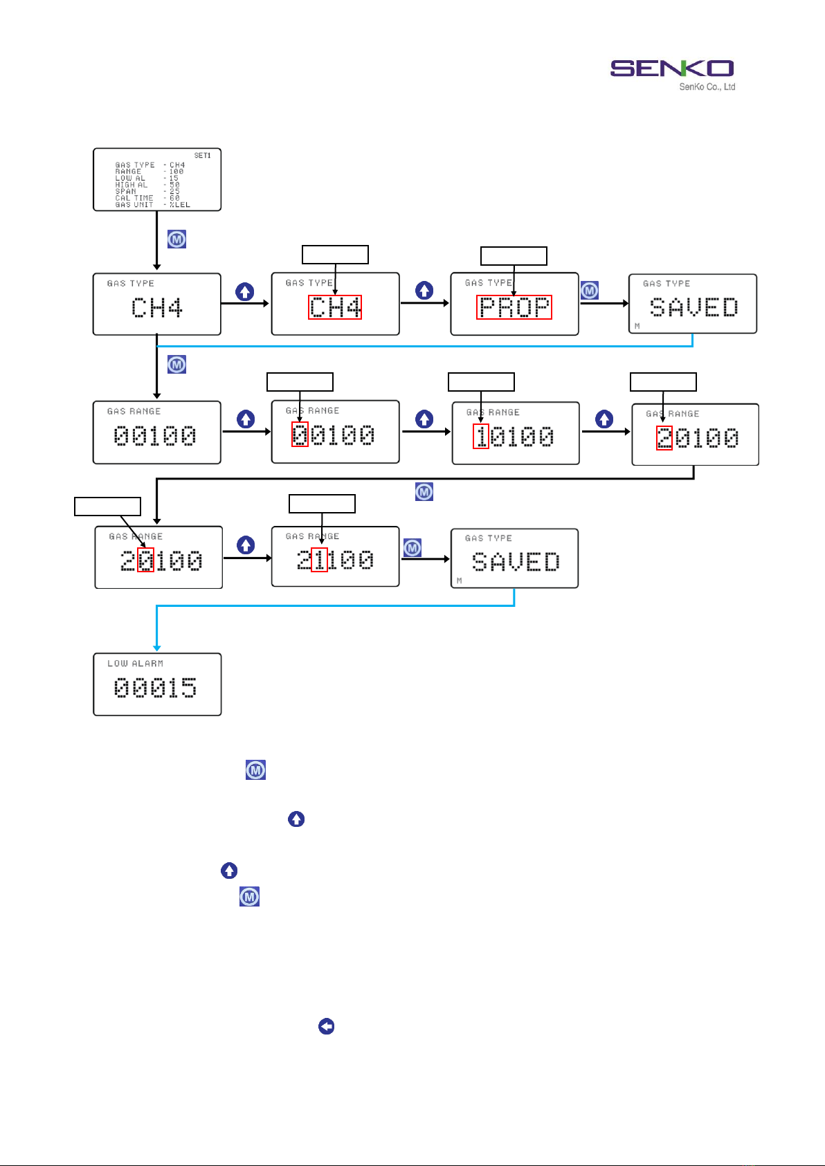
4.4. How to modify the settings [Flow chart]
➢Press MODE key ( ) for 2 seconds by using the magnetic bar in Set Display, in order to enter
Advanced setting.
➢When you press UP key ( ) by using the magnetic bar in Advanced setting display, setting values
flicker, which means they can be changed.
➢Press UP key ( ) when setting values flicker, in order to change the values.
➢Press MODE key ( ) for 2 seconds to save the changes of setting values. These changes are saved
with the indication, “SAVED”.
✓When GAS TYPE is changed, related settings (GAS UNIT, RANGE, ALAMR, etc.) are changed as well.
In order to operate properly, sensor replacement for the gas type and calibration is required.
✓When you press DOWN key ( ) in each mode, the mode goes back to its previous step.
“2sec”
“2sec”
“2sec”
“1sec”
“1sec”
Blinking
Blinking
Blinking
Blinking
Blinking
Blinking
Blinking
SI-100 MANUAL
13
4.5. Zero calibration & Span calibration
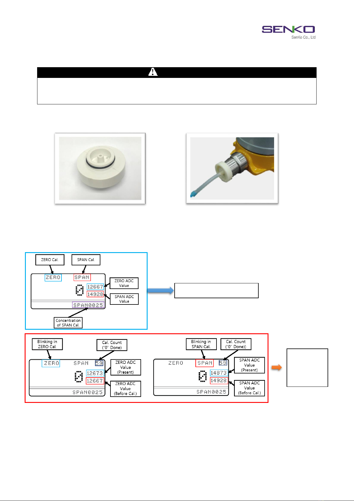
4.5.1 How to connect Calibration cap
➢Correctly attach the calibration cap to the sensor part of the gas detector (SI-100) as the picture
above (using flow meter, etc., flow rate: about 300 SCCM) and inject the calibration gas.
4.5.2 Calibration Mode Explanation
➢In Calibration mode, the ADC values of ZERO and SPAN are displayed. When you conduct
ZERO/SPAN Calibration, Cal. Count starts counting. In the meantime, ADC Value (Present) is
displayed on the above part and ADC Value (Before Cal.) on the below part.
WARNING
Do not conduct Zero Calibration unless you are sure you are in fresh, uncontaminated air. Otherwise,
inaccurate reading can occur, then show that a hazardous atmosphere is safe. If you have any doubts as to
the quality of the surrounding air, Calibration with N2 gas should be done. Failure to follow this warning can
result in serious personal injury or death.
Display of Calibration mode
Display in
ZERO/SPAN
Calibration
SI-100 MANUAL
14
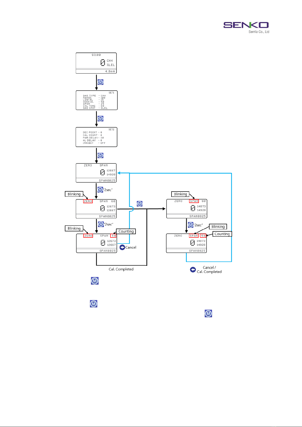
4.5.3 How to enter Calibration Mode
➢Press MODE key ( ) 4 times by using the magnetic bar in Measuring mode, in order to enter
Calibration mode.
➢Press MODE key ( ) for 2 seconds by using the magnetic bar in Calibration mode, in order to
enter ZERO calibration when “ZERO” flickers. Then, press MODE key ( ) for 2 seconds once again
to initiate ZERO calibration.
➢When ZERO calibration is completed, the display automatically shifts to SPAN calibration. The
process is same as ZERO calibration.
✓If ZERO calibration ADC value (EX: 12667) goes beyond the SPAN calibration ADC value (EX: 14928),
you may suspect failure of calibration or malfunction of the gas sensor. In this case, you should
carry out recalibration or receive formal A/S to take appropriate measures for the case.

SI-100 MANUAL
15
5. Certificate

SI-100 MANUAL
16
Other manuals for SI-100
1
Table of contents
Other SENKO Gas Detector manuals

SENKO
SENKO SGT-P User manual

SENKO
SENKO SI-100C User manual

SENKO
SENKO SI-560D User manual

SENKO
SENKO iGas Detector CO2 User manual

SENKO
SENKO SI-100 User manual

SENKO
SENKO SI-H100 User manual

SENKO
SENKO SP-MGTP User manual

SENKO
SENKO SGT User manual

SENKO
SENKO SI-H100 User manual

SENKO
SENKO SP secure User manual


Popular Gas Detector manuals by other brands


Tecnocontrol
Tecnocontrol TS293PM user manual

Technoline
Technoline WL1028 instruction manual

Blackline Safety
Blackline Safety G7 EXO Test guide

Fantini Cosmi
Fantini Cosmi Sicurgas P13 quick start guide

PEMTECH
PEMTECH PT2008 Series Operator's manual

Somogyi Elektronic
Somogyi Elektronic home COG 01 instruction manual


