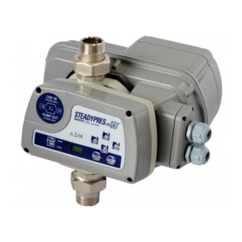
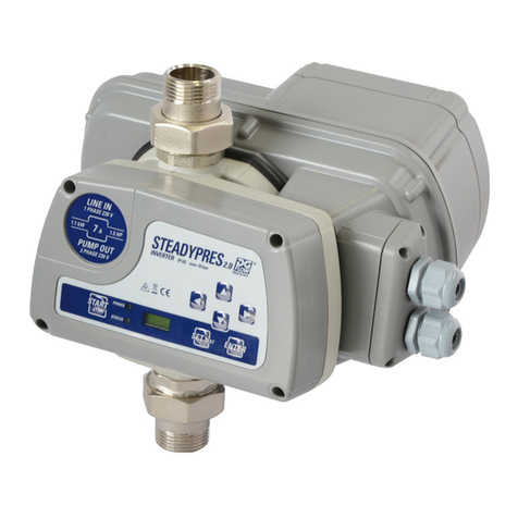
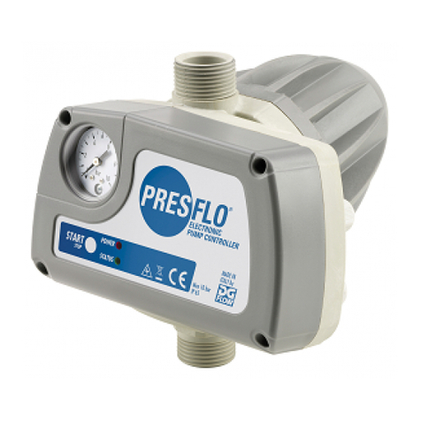
DGFLOW PRESFLO User manual

10183307A_rev.02
0 50 100 150 200 l/min
0 5 10 15 m H2O
PRESFLO
CODE:
V / Hz:
I max:
P start: B
50066/115
~230 / 50 - 60
16 A
1.5 Bar
SN 15060002
CODE:
V / Hz:
I max:
P start: B
50066/115
~230 / 50 - 60
16 A
1.5 Bar
SN 15060002
RUEN FR DEIT ES
ELECTRONIC PUMP CONTROLLER
PRESFLO®is a device that
starts and stops the pump to
which it is tted, thus replacing
traditional pressure switch /
surge tank systems.
The pump is started when, as
a tap is turned on, the pressure
within the system drops below
the “start-up pressure” (Pm),
and is stopped when the ow
USER’S MANUAL
rate required is zero or less
than the “shut-off ow rate”
(Qa).
PRESFLO®’s electronics protect
the pump against unsuitable
operating conditions such as
dry running or repeated start-
ups due to leaks.
Technical specications
Operating conditions
A. Compatible/non compa-
tible uids
PRESFLO®is suitable for use
with clean water and chemical-
ly non-aggressive liquids. If the
uid contains impurities, a lter
should be tted upstream.
B. Environmental conditions
PRESFLO®should not be used
where there is the risk of an
explosion. The temperature
of the location should range
between 0°C and 40°C, and
the humidity should not exceed
90%.
C. Power supply
Make sure that the variation
in the power supply is never
more or less than 10 % of the
RATING value.
Higher values may cause
damage to the electronic
components.
PRESFLO®can only be used
with single-phase pumps.
Working area
Flow rate
Pressure
Shut-off ow rate
Start-up pressure
2l/min (0,5 gpm)
Red =
Blue =
Yellow =
Qa
Pm
Safety regulations
Before installing or using
PRESFLO®, read this manual
carefully and thoroughly.
The pump should be installed
and serviced by qualied per-
sonnel, responsible for making
the hydraulic and electrical
connections in compliance with
the relevant regulations.
DGFLOW®shall not be held lia-
ble for any damage relating to,
or resulting from, an improper
use of the product, or for any
damage relating to, or resulting
from, servicing or repairs carri-
ed out by unqualied personnel
and/or with non-OEM spare
parts.
The warranty, which is valid
for 24 months from the date
of purchase, will no longer be
applicable should the product
suffer damage as a conse-
quence of the use of non-OEM
spare parts, tampering or
improper use.
When starting the installation,
check the following:
- the power supply is switched
off.
- the power lines can withstand
the maximum current.
- the cable bushings and circuit
board cover have been properly
assembled and secured ( see
Electrical Connections ).
- Power supply network must
be tted with proper protection
device (fuse or magneto-
thermal relay) upstream of
PRESFLO®
When servicing the product,
check the following:
- the system is not pressurised
(turn a tap on)
- the power supply is switched
off.
Emergency Stop
When in use, the pump can
be stopped in the event of an
emergency:
press STOP/RESTART.
PRESFLO®is put STAND-BY.
Never disassemble
water accumulator
Water accumulator
Losses
- Voltage: ~230 Volt / ~115 Volt
- Frequency: 50-60 Hz
- Current: 10A, max 12A for 3 sec.
- Current: 12A, max 16A for 3 sec.
- Protection grade: IP 65
-
Start-up pressure (Pm):
0,8/1,5/2,2 bar
(12/22/32 psi)
- Shut-off ow rate (Qa): 2 litres/min (0,5 gpm)
- Connections: 1” BSP / 1” NPT
- Maximum working pressure: 10 bar (145 psi)
- Bursting pressure: 40 bar (580 psi)
- Weight: 650 g
- Protection against:
- dry running (automatic restart)
- repeated start-ups
- Max room temperature: 40°C
- Max liquid temperature: 55°C
- Type of drive: 1C
- Max manual operations on
push button: 1000
- Max automatic operations
on relay: 100000
- Class 3A PTI
- Pollution degree : 2
- Max rated voltage pulse: 2,5 kV
- 230V 12A for EMC test
- Pressure operating
differential: 10 bar
Before installing,
the product, check that
the RATINGS correspond
with those required.
2,2 bar (32 psi)
1,5 bar (22 psi)
0,8 bar (12 psi)

Preliminary checks
Take the PRESFLO®out of
the packaging and check the
following:
- check for damage,
- check the RATINGS corre-
spond with those required,
- that the cable bushings and
screws are in place,
- that PRESFLO®’s inlets and
outlets are clean and free of
any packaging materials,
- that the check valve moves
smoothly.
Hydraulic connections
the joint in two pieces allows
rapid connection to the system.
DO NOT apply sealant inside the
2-piece joint because it already
has an internal o-ring.
Orientation
PRESFLO®can be
installed at any angle
depending on the
ow direction, as
indicated in the diagrams.
Position
PRESFLO®can either be tted
directly to the pump outlet or
anywhere along the delivery
line. Never install taps between
the pump and PRESFLO®. Do
not install a non-return valve
between PRESFLO®and the
taps, meanwhile it is possible,
although not necessary, to in-
stall a non-return valve on the
suction piping of the pump.
Installation
Red =
Blue =
Yellow =
Attention
The pressure applied
by the water column above
PRESFLO®must not exceed
that of the pump start-up
pressure (Pm). If, for example,
PRESFLO®is installed at a
height 15 m (50 ft) below that
of the highest tap in the sy-
stem, the pressure detected by
PRESFLO®will be approxima-
tely 1.5 bar (22 psi). A model
with Pm = 2.2 bar (32 psi)
should, therefore, be installed
in order to guarantee that the
pump is started when a tap is
turned on.
Attention
The maximum pressure
produced by the pump must be
at least 1 bar (15 psi) higher
than the start-up pressure
(Pm). If the pressure produced
by the pump is too low,
PRESFLO®will stop the pump
and indicate a ‘dry running’
error message.
First start-up
Priming the pump
For instructions on how to
prime (ll) the pump, see the
pump manual.
Attention
PRESFLO®is tted with a
check valve: do not use the
PRESFLO®’s outlet to ll the
pump for priming.
Switching the pump on
The red (Power On) LED lights
up; PRESFLO®instantly detects
that there is no pressure within
the system and
starts the pump
(the green
‘Pump On’ LED lights up).
If, within 15 seconds of starting
up, PRESFLO®
does
not detect the
correct priming of
the pump, it stops the pump
and indicates a ‘dry running’
error message.
Attention
When the pump is star-
ted for the rst time, it
may have to be run for
longer in order to complete the
priming procedure.
Press the
STOP/RESTART
button
to restart the
pump and
complete the
priming procedure.
Motor
Line
Nut
Seal
Cable bushing
Attention! The cable
bushings and circuit board
cover must be properly
assembled and secured
in order to guarantee IP
65 grade protection of the
electrical components.
Electrical con-
nections
The electrical
connections
should be made
as indicated in the
diagram which
can also be found
on the inside of
the circuit cover.
NOTE 1 - DRY RUN PROTECTION = there is no ow and the
pressure is lower than that of the pump start-up pressure (Pm).
It occurs when there is no water. After 15 seconds PRESFLO®
stops the pump and indicates an ERROR message. PRESFLO®
AUTOMATICALLY tries to resume NORMAL SERVICE at intervals
of increasing time (1, 15, 30, 60 minutes and successively once
every hour - 24 H for AU/NZ -). If PRESFLO®detects any pressure
and/or ow, NORMAL SERVICE is resumed, otherwise, the pump is
stopped again until the next attempt is made. A MANUAL attempt
to resume NORMAL SERVICE can be made at any time.
NOTE 2 - EXCESSIVE STARTS = the repeated stopping and
starting of the pump at intervals of less than 1 minute from each
other. This occurs when the ow rate is less than 2 litres/min. This
may cause damage to the pump. In event of small leaks (dripping),
PRESFLO®’s water accumulator guarantees that the pump starts/
stops at time intervals of over 1 minute (less than 60 starts/hour)
and that FREQUENT START-UP errors do not occur. In the event of
a major leak or extended use at excessively low ow rates (less
than 2 litres/min), the pump may be started/stopped as often as
once every few seconds, putting the pump at risk of damage. In
this case, after about 40 minutes, PRESFLO®stops the pump for
the following 30 minutes (in order to let it cool down) and indicates
an ERROR message. If the time interval between the starts-stops
is more than 10 seconds (and therefore poses less of a risk to the
pump), PRESFLO®will allow the pump to be used for more than
30 minutes. Once that enough time has passed to allow the pump
to cool down it is restarted AUTOMATICALLY. The pump may be
restarted MANUALLY any time.
20 m (65 ft)
12 m (40 ft)
6 m (20 ft)

1
2a
2c
2b
3
4a
4b
Operation
PRESFLO®is switched off.
Press briey or hold down
= nothing happens
Power is restored = PRESFLO®
resumes NORMAL SERVICE and
starts the pump (if necessary).
No power supply
The system is pressurised.
All taps are turned off. There is
no demand for water.
PRESFLO® detects an assembly pressure
higher than that of the start-up pressure
(Pm) and no ow.
Press briey = the pump is
started manually and runs for
a few seconds before stopping
again.
Hold down = lthe pump is put STAND-
BY. For instructions on how to reactivate
the pump, see point 3.
A tap is turned on = as soon as the
pressure falls below the start-up pressure
(Pm), the pump is started.
NORMAL SERVICE: the pump is inactive.
The pump has been
stopped manually.
The pump will
remain inactive until a new
command is given.
Press briey
= nothing happens.
Hold down
= the pump resumes NORMAL SERVICE.
See points 2a - 2b.
The system has just
ceased to require
water. All taps are
closed. The pump is still in operation.
The system is pressurized. PRESFLO®
detects a system pressure higher than
the start-up
pressure (Pm) and no ow.
Press briey or hold down =
the pump is stopped and put in
STAND-BY
To reset see point 3.
If the absence of ow lasts for a few
seconds the pump is stopped
STAND-BY
NORMAL SERVICE: pump during shutdown
See NOTE 1)
PRESFLO®has
detected that the
pump is dry running and has therefore
stopped it TEMPORARILY.
Press briey = the pump is started and
manually and resumes NORMAL SERVICE.
See points 2a - 2b.
Hold down
= the pump is put STAND-BY.
For instructions on how to
reactivate the pump, see point 3.
ERROR: stopped temporarily due to DRY RUNNING
The assembly requires water.
One or more taps are turned on.
PRESFLO®detects a ow; the
assembly pressure is normally higher
than the START-UP pressure, but it may
also be lower.
Press briey or hold down
= the pump is stopped and put
STAND-BY.
For instructions on how to reac-
tivate the pump, see point 3.
The taps are turned off = Sif there is
no ow for a few seconds, the pump is
stopped.
NORMAL SERVICE: the pump is running
(see NOTE 2)
PRESFLO®has
detected that the
pump starting-up too often and has therefore
stopped it TEMPORARILY.
Press briey = the pump
is started and manually and
resumes NORMAL SERVICE.
See points 2a - 2b.
Hold down
= the pump will not restart and goes OUT
OF ORDER.The pump is put STAND-BY. For
instructions on how to reactivate the pump,
see point 3.
ERROR: temporary shut down due to FREQUENT
START UP
= Off = On = Flashing

5
6
3
2
4
1
Made in Italy by
DGFLOW srl Via Emilia, 5
46030 Bigarello (Mantova) Italy
tel. +39 0376 340922
fax. +39 0376 249525
info@dgow.it - www.dgow.it
CODE:
V / Hz:
I max:
P start: B
50066/115
~230 / 50 - 60
16 A
1.5 Bar
SN 15060002
Exploded view of spare parts
Attention: when ordering spare
parts, always state the position
n° from the diagram below and
the product code number found
in the pressure-ow regulator
technical data table.
1 - Circuit board cover
2 - Pressure gauge
3 - Circuit board
4 - Cable bushings
5 - Valve unit
6 - two-pieces joint with OR
Article
Version
Size
Disposal
When disposing of any
PRESFLO®parts, adhere
to the relevant laws and
regulations in force in
the country in which the
equipment is being used.
Do not dispose of any
polluting parts in
the environment.
Statement of Compliance: we declare, under our own respon-
sibility, that the product in question is in compliance with the fol-
lowing European Directives and national implementation provisions
2014/35/CE Low Voltage Directive
2011/65/CE (RoHS)
2012/19/CE - 2003/108/CEE (WEEE)
2014/30/CE Electromagnetic Compati-
bility Directive (EMC)
EN 60730-2-6
EN 61000 6-3
Bigarello 01.06.16
DGFLOW S.r.l.
President
Stefano Concini
Problems Signals Possible causes Solutions
PRESFLO®
will not turn on No power Check the electrical connections
The pump will
not start when
a tap is turned on
PRESFLO®model with an inadequate
start-up pressure (Pm) for the chosen
application.
Relocate PRESFLO®to another position
Install a model with a higher start-up pressure (Pm)
Faulty electrical connections or
pump out of service
Check the electrical connections and that the pump
is working
PRESFLO®“STAND-BY” Reset PRESFLO®(See Operation, point 3).
PRESFLO®in temporary shut down
due to “DRY RUNNING” due to lack
of water
Wait for the automatic restart or press START to
restart manually (See Operation, point 4a)
Maximum pump pressure is
insufcient
Replace the pump with one with more suitable
characteristics
Install a model with a lower start-up pressure (Pm)
PRESFLO®in temporary shut down
due to “FREQUENT START-UP”
Wait for the automatic restart or press START to
restart manually (See Operation, point 4b). Remove
any cause of leakage from system or install an
expansion tank
The pump
delivers no or low
pressure
Filters or pipes may be partly blocked Check the water pipes
PRESFLO®’s valve will not open
completely
Check that the valve is not blocked by any foreign
objects and clean if necessary
The pump stops
and starts
repeatedly
Leaks within the system (less than
the shut-off ow rate Qa)
Check the hydraulic connections and repair any
leaks. If a leak cannot be repaired, install an
expansion tank
The pump will
not stop
The ow rate is higher than the
shut-off ow rate (Qa)
Make sure that all taps are turned off and that
there are no leaks within the system
PRESFLO®’s check valve will not
close or is damaged
Check that the valve is not blocked by any foreign
objects and clean if necessary
= Off = On = Flashing
Other DGFLOW Controllers manuals
