Elta Ezifit In-Wall SEIE User manual

Ezifit In-Wall SEIE
Installation and Maintenance Instructions
THESE INSTRUCTIONS MUST BE READ FULLY BEFORE
COMMENCING INSTALLATION
Code
Supply FL Amps Power Watts r/min
SEIE150 230V/1Ph/50Hz 0.22/0.25/0.29 50/60/75 1260/1920/2400
1.0 GENERAL
1.1 It is important these Installation and Maintenance Instructions are fully adhered to.
1.2 Full details of the unit supplied are shown on the product nameplate. If in doubt about any detail
contact Elta Fans Ltd or its agents for clarification.
1.3 All electrical installation must be carried out by suitably qualified and competent
personnel in accordance with all current statutory requirements.
1.4 These instructions cover only the Elta Fans Ltd product and do not include the supply or
installation of any safety equipment that may be required e.g. adequate guarding or
protection from rotating parts and proper electrical isolation.
1.5 Any declarations made by Elta Fans Ltd about product installation and safety, are
dependant on the fan equipment being used within installations which themselves
meet the requirements of the relevant Standards and Directives of your region.

1.6 The fan is designed for use in an ambient temperature of -20oC up to +50oC and up to 95% relative
humidity. The fan is not suitable for corrosive or explosive atmospheres.
1.7 The installer should provide easy access to the fan to facilitate future maintenance.
1.8 The installer should ensure the fan is adequately supported.
1.9 This product is not intended for use by persons (including children) with reduced physical, sensory
or mental capabilities, or lack of experience and knowledge, unless they have been given
supervision or instruction concerning use of the product by a person responsible for their safety.
Children should be supervised to ensure that they do not play with the product.
2.0 INSTALLATION
WARNING – The fan must be isolated from the power supply during installation and
maintenance. The fan must be earthed in accordance with the local regulations.
2.1 Upon receipt, the fan equipment should be visually inspected to check for any damage. Ensure that
the impeller is free to rotate.
2.2 If there are any queries concerning the fan equipment, Elta Fans Ltd should be contacted prior to
the installation.
2.3 The fan is designed for in-wall flush mounting in the desired position to suit the application.
2.4 Prepare the opening in the wall 265mm high x 240mm wide.
2.5 Remove the grille from the fan by un-doing the grille retaining screw.
2.6 Position the fan in the opening with the retaining screw hole uppermost.
2.7 Using the fan flange as a template mark and drill the holes for the fasteners provided.
2.8 Check the details on the motor rating plate to ensure that the correct power supply (voltage,
frequency and phase) is available.
An incorrect power supply will lead to permanent damage to the fan motor.
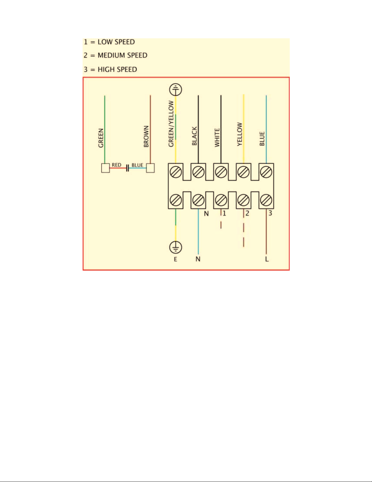
2.9 Refer to the appropriate wiring diagram. Ensure that all earth connections are made.
2.10 Means for electrical disconnection must be incorporated in the wiring installation in accordance with
the relevant wiring and electrical regulations.
2.11 Fix the fan to the wall with the fasteners provided.
2.12 Refit the grille and grille retaining screw.
2.13 Precaution must be taken to locate the exhaust discharge terminal so as to avoid the backflow of
gases into the room from the open flue of gas or other fuel burning appliances.
3.0 START-UP
3.1 Before power is supplied to the unit, check that the wiring is correct as per the fan connection
diagram.
3.2 At initial start-up, check that impeller rotation and airflow direction is correct.
3.3 Check that the motor amperage draw does not exceed the nameplate rating.
4.0 FAN MAINTENANCE
4.1 Inspection of the fan at least once every 12 months is recommended to ensure that the motor, fan
blades, and supporting guards, are clean. Any build up of dust and deposits on the blades or
guards should be removed using a non-abrasive cleaner.
4.2 All fastenings should be checked for tightness. In addition, all rotating items should be checked.
4.3 Bearings are of the ‘sealed for life’ type and will not need a detailed inspection.
WARNING – This fan is fitted with an auto-reset thermal cut-out which switches the fan off in the
event of a fault condition.
Once the motor cools down the fan may start unexpectedly.
Only a suitably qualified and competent person may carry out maintenance after the electrical
supply has been isolated.

WIRING
220-240V 1Ph 50Hz Supply
GUARANTEE
Elta Fans Ltd will, free of charge, within a period of 1 year from the date of despatch from their
works, repair or at its option replace any goods which are proved to have defects as a result of
defective materials or workmanship. The goods MUST be returned to Elta Fans Ltd carriage paid for
examination.
Elta Fans Ltd
17 Barnes Wallis Road
Segensworth East Industrial Estate
Fareham, Hampshire, PO15 5ST, United Kingdom
Visit: eltafans.com
e-mail: mailbox@eltafans.co.uk
Applied Technology: Tel: +44(0) 1489 566500 Fax: +44(0) 1489 566555
Building Services: Tel: +44(0) 1384 275800 Fax: +44(0) 1384 275810
Export: Tel: +44(0) 1489 566500 Fax: +44(0) 1489 566555
SEIE Inst Issue 1: 12-10-07

Ezifit Thru-Wall SEWE
Installation and Maintenance Instructions
THESE INSTRUCTIONS MUST BE READ FULLY BEFORE
COMMENCING INSTALLATION
Code
Supply FL Amps Power Watts r/min
SEWE154 230V/1Ph/50Hz 0.16 34 1380
SEWE152 230V/1Ph/50Hz 0.30 65 2460
1.0 GENERAL
1.1 It is important these Installation and Maintenance Instructions are fully adhered to.
1.2 Full details of the unit supplied are shown on the product nameplate. If in doubt about any detail
contact Elta Fans Ltd or its agents for clarification.
1.3 All electrical installation must be carried out by suitably qualified and competent
personnel in accordance with all current statutory requirements.
1.4 These instructions cover only the Elta Fans Ltd product and do not include the supply or
installation of any safety equipment that may be required e.g. adequate guarding or
protection from rotating parts and proper electrical isolation.
1.5 Any declarations made by Elta Fans Ltd about product installation and safety, are
dependant on the fan equipment being used within installations which themselves
meet the requirements of the relevant Standards and Directives of your region.
1.6 The fan is designed for use in an ambient temperature of -20oC up to +50oC and up to 95% relative
humidity. The fan is not suitable for corrosive or explosive atmospheres.
1.7 The installer should provide easy access to the fan to facilitate future maintenance.

1.8 The installer should ensure the fan is adequately supported.
1.9 This product is not intended for use by persons (including children) with reduced physical, sensory
or mental capabilities, or lack of experience and knowledge, unless they have been given
supervision or instruction concerning use of the product by a person responsible for their safety.
Children should be supervised to ensure that they do not play with the product.
2.0 INSTALLATION
WARNING – The fan must be isolated from the power supply during installation and
maintenance. The fan must be earthed in accordance with the local regulations.
2.1 Upon receipt, the fan equipment should be visually inspected to check for any damage. Ensure that
the impeller is free to rotate.
2.2 If there are any queries concerning the fan equipment, Elta Fans Ltd should be contacted prior to
the installation.
2.3 The fan is designed for surface wall mounting in the desired position to suit the application.
2.4 The fan is designed for connection to 150mm ducting.
2.5 Cut either a circular or square hole in the wall between 160-190mm diameter/square. Ensure a
clean edge.
2.6 Check the fit of the duct (and clamp) in the cut hole. The duct must be positioned horizontally
through the hole.
2.7 Fit the foam sealing tape supplied to the rear of the fan housing. Run the tape around the outside of
the four mounting holes and ensure that the tape join is along the bottom of the housing for an
effective seal.
2.8 Remove the cover from the fan by un-doing the side fixing screws.
2.9 Position the fan on the wall with the airflow arrow pointing down.
2.10 Using the fan as a template mark and drill holes for the power cable and fastening screws.
2.11 Pull the power cable through the assigned hole and attach the ducting to the spigot.
2.12 Fix the fan to the wall with the appropriate fastening screws.
2.13 Check the details on the motor rating plate to ensure that the correct power supply (voltage,
frequency and phase) is available.
An incorrect power supply will lead to permanent damage to the fan motor.
2.14 Refer to the appropriate wiring diagram. Ensure that all earth connections are made.
2.15 Means for electrical disconnection must be incorporated in the wiring installation in accordance with
the relevant wiring and electrical regulations.
2.16 Refit the cover and side fixing screws.
2.17 Precaution must be taken to locate the exhaust discharge terminal so as to avoid the backflow of
gases into the room from the open flue of gas or other fuel burning appliances.
3.0 START-UP
3.1 Before power is supplied to the unit, check that the wiring is correct as per the fan connection
diagram.
3.2 At initial start-up, check that impeller rotation and airflow direction is correct.
3.3 Check that the motor amperage draw does not exceed the nameplate rating.
4.0 FAN MAINTENANCE
4.1 Inspection of the fan at least once every 12 months is recommended to ensure that the motor, fan
blades, and supporting guards, are clean. Any build up of dust and deposits on the blades or
guards should be removed using a non-abrasive cleaner.
4.2 All fastenings should be checked for tightness. In addition, all rotating items should be checked.
4.3 Bearings are of the ‘sealed for life’ type and will not need a detailed inspection.
WARNING – This fan is fitted with an auto-reset thermal cut-out which switches the fan off in the
event of a fault condition.

Once the motor cools down the fan may start unexpectedly.
Only a suitably qualified and competent person may carry out maintenance after the electrical
supply has been isolated.
WIRING
220-240V 1Ph 50Hz Supply
GUARANTEE
Elta Fans Ltd will, free of charge, within a period of 1 year from the date of despatch from their
works, repair or at its option replace any goods which are proved to have defects as a result of
defective materials or workmanship. The goods MUST be returned to Elta Fans Ltd carriage paid for
examination.
Elta Fans Ltd
17 Barnes Wallis Road
Segensworth East Industrial Estate
Fareham, Hampshire, PO15 5ST, United Kingdom
Visit: eltafans.com
e-mail: mailbox@eltafans.co.uk
Applied Technology: Tel: +44(0) 1489 566500 Fax: +44(0) 1489 566555
Building Services: Tel: +44(0) 1384 275800 Fax: +44(0) 1384 275810
Export: Tel: +44(0) 1489 566500 Fax: +44(0) 1489 566555
SEWE Inst Issue 1: 12-10-07
This manual suits for next models
1
Table of contents
Other Elta Fan manuals

Elta
Elta 9050N5 User manual

Elta
Elta 9015 User manual

Elta
Elta Skyflow SSMF User manual

Elta
Elta ARCO D User manual

Elta
Elta Quietflow SQS Series User manual

Elta
Elta 9095N5 User manual

Elta
Elta 9050N2 User manual

Elta
Elta Multiflow SMB Instruction Manual

Elta
Elta 9016N6 User manual

Elta
Elta SAX Series User manual